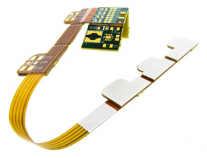
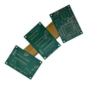
Choosing a rigid flex PCB manufacturer USA buyers can rely on starts with one practical question: does the supplier’s manufacturing location, process capability and service model fit your specific project? A nearby factory may be essential for controlled defense data or a contractually required domestic build. For many commercial, medical and industrial projects, however, engineering support, a controlled stackup, dependable sourcing, assembly capability and traceable production can matter more than distance alone.
EBest Circuit (Best Technology) is a China-based PCB and PCBA manufacturer serving US customers. Your team can combine DFM review, PCB fabrication, component sourcing, PCBA and testing coordination through one supplier. This gives you a practical alternative when the project does not require US production and you need prototype-to-production support, documented quality controls and a project-specific delivery plan.
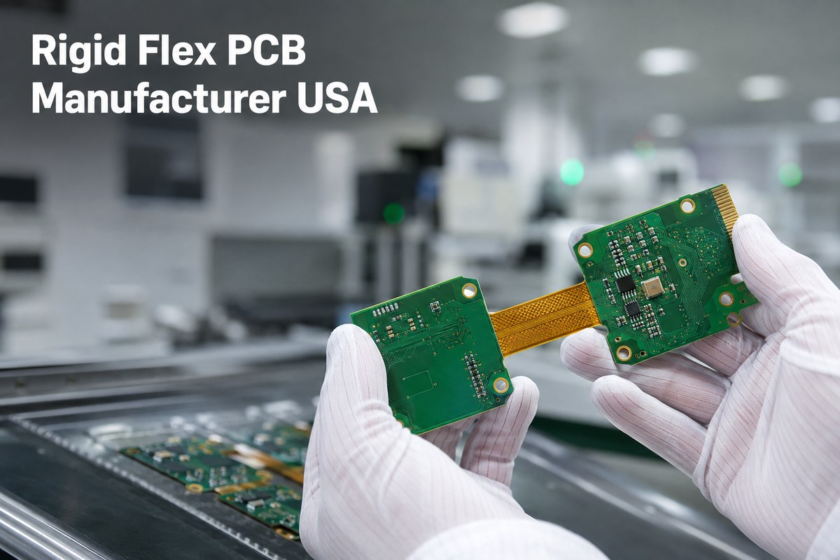
Top 10 Rigid Flex PCB Manufacturers in the USA
The following shortlist focuses on suppliers with a stated US manufacturing presence or established US rigid-flex operations. Because some companies also operate global facilities, buyers should confirm the fabrication and assembly location for their exact part number before placing an order.
| Manufacturer | US manufacturing position | Best suited to |
|---|---|---|
| Sierra Circuits | California fabrication and assembly | Quick-turn, HDI and complex rigid-flex projects |
| Rigiflex Technology | Anaheim, California facility | Fast prototypes and custom flex or rigid-flex boards |
| Cirexx | States 100% USA manufacturing | High-reliability, ITAR and one-stop projects |
| All Flex Solutions | Minnesota-based rigid-flex production | Medical, aerospace and high-vibration applications |
| Excello Circuits | Anaheim, California manufacturing | Complex aerospace, medical and industrial boards |
| Summit Interconnect | Multiple North American facilities | Mission-critical and advanced-technology PCBs |
| TTM Technologies | Global manufacturer with US operations | High-layer-count, HDI and scaled programs |
| Printed Circuits | Minneapolis, Minnesota manufacturer | Custom, high-performance rigid-flex boards |
| Sierra Assembly Technology | Chino, California operation | Domestic fabrication, assembly and testing |
| Rush PCB | California-based PCB and PCBA supplier | Fast prototypes and turnkey assembly |
This is a sourcing shortlist, not a universal ranking. The right choice depends on where your board will be made, whether assembly is performed at the same site, which certifications apply to that site, and whether the supplier’s proven process window matches your released design.
What Should USA Buyers Compare Between Rigid Flex PCB Suppliers?
The most useful comparison is not the number of capabilities shown on a website. It is whether each supplier can give your team a controlled and repeatable route from released data to an accepted assembly.
Compare these points in every quotation:
- Manufacturing location: Identify the facility that will fabricate the board and the facility that will assemble it.
- Technology fit: Match layer count, flex construction, line and spacing, hole structure, materials, copper weight and impedance requirements.
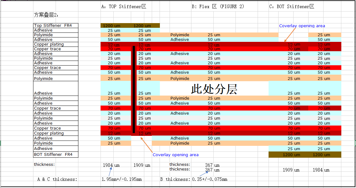
- Engineering response: Confirm who will review the stackup, bend zones, coverlay openings, stiffeners and panel design before production.
- Prototype-to-production continuity: Check whether the same approved materials, stackup and process controls can continue into repeat orders.
- Assembly scope: Establish whether component sourcing, SMT, through-hole assembly, programming and testing are included.
- Quality evidence: Define the inspection, electrical test, microsection, impedance report, first-article or lot records required with the shipment.
- Change control: Require approval before changes to materials, stackup, components, processes or manufacturing location.
- Lead-time basis: Make sure the quoted clock starts from the same point—normally after data approval and material availability.
A low unit price has little value if the quotation excludes tooling, electrical testing, stiffeners, assembly fixtures or the records needed for customer approval. Ask suppliers to state these items clearly so that the commercial comparison reflects the same scope.
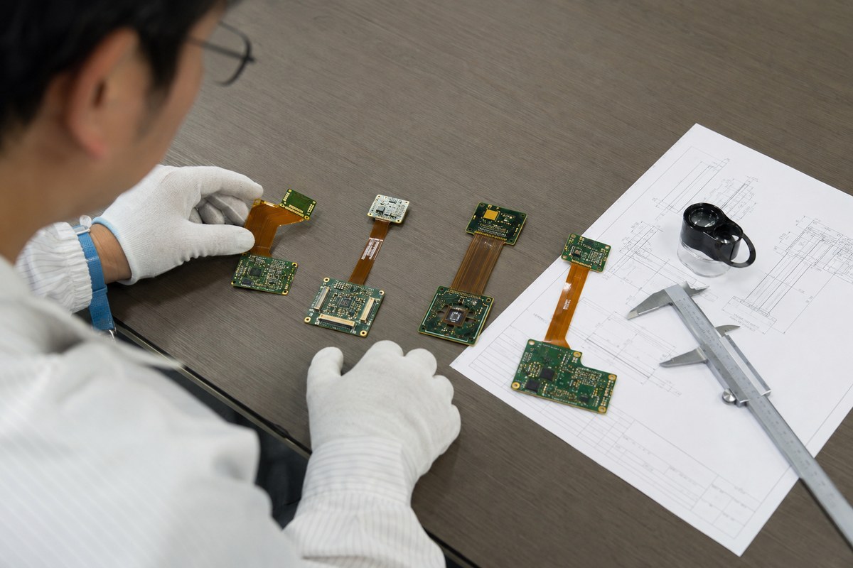
Which Rigid Flex PCB Manufacturing Capabilities Matter for USA Projects?
For USA rigid-flex projects, capability should be checked against the released design—not a generic equipment list. At EBest Circuit, we review the rigid and flexible layer structure, materials, smallest features, bending requirements, surface finish and assembly scope before confirming whether a project fits our manufacturing process.
Our relevant rigid-flex PCB and PCBA capabilities include:
| Capability | EBest Circuit capability |
|---|---|
| Rigid-flex layers | 2–20 layers, subject to construction review |
| Finished thickness | 0.3–3.0 mm |
| Thickness tolerance | Above 1.0 mm: ±10%; 1.0 mm or below: ±0.10 mm |
| Flex construction | Inner-flex or outer-flex structures |
| Flex materials | PI, adhesiveless flex core, coverlay and stiffeners |
| Rigid materials | FR4, high-Tg FR4 and low-flow prepreg |
| Fine features | Fine line/space, BGA pads, laser vias and mechanical drilling |
| Controlled impedance | Review and production to ±10% for applicable structures |
| Surface finishes | ENIG and other project-specific finishes |
| PCBA support | Component sourcing, SMT, connector assembly, inspection and testing |
For each RFQ, we compare these capabilities directly with the customer’s files, including:
- rigid-layer and flex-layer count, stackup and finished thickness;
- minimum trace, spacing, hole and via structure;
- flex-core, coverlay, stiffener and low-flow material requirements;
- bend direction, bend area and rigid-to-flex transition geometry;
- controlled-impedance traces and copper construction;
- contact finish, connector areas and mechanical tolerances;
- component packages and required assembly support;
- electrical test, AOI, X-ray or other inspection requirements.
This gives USA buyers a useful answer before tooling and material preparation begin: whether EBest’s proven process capability matches the specific rigid-flex PCB and PCBA being released.
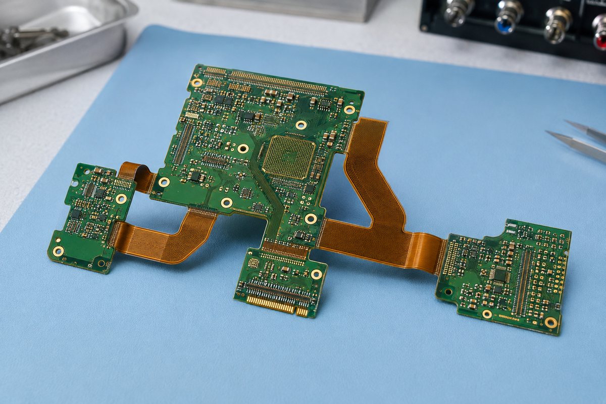
When Is USA-Based Rigid Flex PCB Manufacturing Necessary?
Choose a US manufacturing route when the project’s legal, contractual or security requirements make domestic control part of the deliverable. Typical situations include:
- the customer contract explicitly requires US fabrication or assembly;
- controlled technical data cannot be transferred to foreign persons or overseas facilities;
- an ITAR, CUI, defense or government program imposes approved-site requirements;
- the customer’s qualification locks production to a named US facility;
- same-site engineering access or an urgent domestic build is more important than unit cost;
- the program requires a domestic supply-chain or country-of-origin condition.
Do not assume that every aerospace, medical or industrial rigid-flex board must be manufactured in the United States. The controlling requirement should come from the contract, export-control assessment, customer quality plan and approved supplier rules. Buyers should verify the actual manufacturing site rather than relying only on a US sales address.
When Should USA Buyers Choose an Overseas Rigid Flex PCB Supplier?
An overseas partner can be a stronger commercial fit when offshore production is permitted and the buyer needs more than bare-board fabrication. EBest is suitable for projects that benefit from:
- early DFM review of stackup, bend areas, coverlay, stiffeners and panelization;
- PCB fabrication, component sourcing and PCBA under one coordinated workflow;
- prototypes and small batches that can progress into repeat production;
- BOM review and an optimization list submitted for customer approval;
- batch-level material and production traceability;
- inspection and testing matched to the released specification;
- a consolidated quotation covering the complete manufacturing scope.
The decision should be based on the total project result: engineering response, usable yield, documentation, assembly quality, delivery and landed cost. If the files can legally be manufactured in China and the supplier’s process capability matches the part, EBest can reduce the handoffs that occur when PCB fabrication, sourcing and assembly are placed with unrelated vendors.
Case Study: EBest Rigid Flex PCB for a US Customer
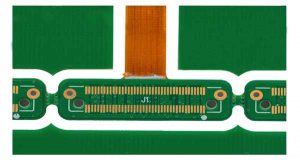
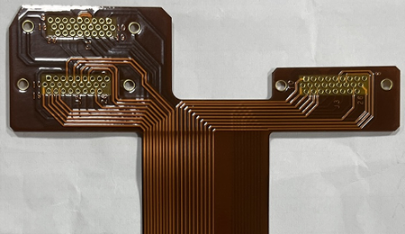
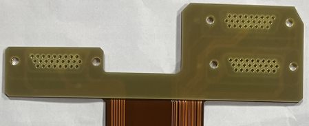
A US customer needed a rigid-flex interconnect that combined a flexible connection area with a rigid contact section. The mating edge required a wear-resistant finish and controlled mechanical geometry, so the copper type, rigid-section thickness, resin-filled features, hard-gold fingers and bevel had to be manufactured as one coordinated structure.
The released board requirements included:
| Item | Project requirement |
|---|---|
| Construction | 4-layer rigid-flex PCB |
| Copper | 1 oz rolled-annealed copper |
| Rigid section | 0.062-inch FR4 |
| Via treatment | Resin-filled features |
| Contact finish | 30 μin hard gold fingers |
| Contact edge | 30-degree bevel |
| Initial build | 60 finished boards plus 2 process samples |
Before manufacturing, EBest reviewed how these requirements interacted. Rolled-annealed copper supported the flexible section, while the FR4 rigid area supported the contact interface. Resin filling, hard-gold thickness and bevel geometry were checked together so the finished edge could meet the released mating requirements.
The project then moved through material preparation, rigid-flex fabrication, contact plating, bevel processing, inspection and electrical testing under the approved production data. EBest completed the order and shipped the finished boards to the customer.
The customer received more than a four-layer board. The delivered parts combined the required flexibility, rigid mechanical support and durable contact interface in one finished rigid-flex interconnect, ready for the customer’s next equipment-validation stage.
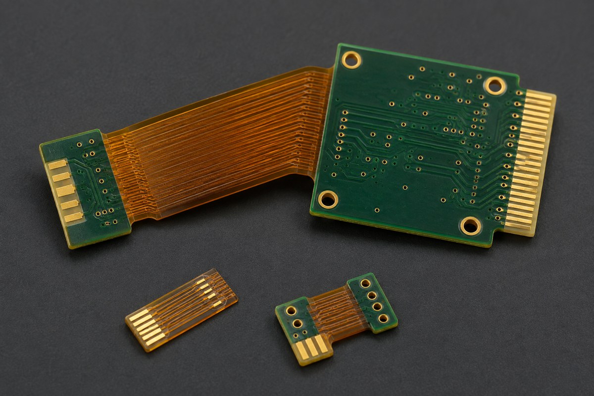
How Does EBest Control Rigid Flex PCB Fabrication for USA Projects?
Reliable fabrication begins with one approved data set. EBest checks the Gerber or ODB++ data, fabrication drawing, stackup, drill files, impedance requirements and mechanical information before releasing the job.
The main controls include:
- Stackup confirmation: Align rigid cores, flex cores, coverlay, bonding materials and copper construction with the released drawing.
- Bend-area review: Keep vias, sharp copper corners and unsuitable feature transitions away from defined flexing zones.
- Material control: Verify the specified laminates, polyimide, copper, coverlay, stiffeners and surface finish against the order.
- Registration and lamination control: Manage the alignment of thin flexible layers and rigid sections throughout the build.
- Impedance and feature inspection: Apply the specified coupons, measurements, AOI, microsections or other checks required by the project.
- Electrical testing: Test the finished board to the released netlist before assembly or shipment.
- Revision and change control: Keep production records connected to the correct revision and obtain approval for material or process changes when required.
Assembly requirements are reviewed at the same time because rigid-flex boards need suitable support during printing, placement, reflow, handling and test. This early coordination helps protect flexible areas while ensuring that BGA, CSP, fine-pitch and connector locations receive the appropriate inspection method.

What Can USA Buyers Gain From EBest’s Rigid Flex PCB Services?
- Faster engineering decisions: one commercial contact coordinates support from PCB, component and PCBA engineers.
- Fewer build surprises: DFM review identifies stackup, bend-zone, panel and assembly questions before production.
- One simpler handoff: PCB fabrication, component sourcing and PCBA are managed through EBest’s own PCB and PCBA factories.
- More sourcing options: a network of more than 1,000 supply-chain partners supports component procurement, subject to customer approval.
- Traceable orders: material batches, product lots, production cycles and order status can be retrieved through EBest’s digital workshop.
- Quality-system support: EBest operates under ISO 9001, ISO 13485, IATF 16949 and AS9100D quality systems.
- A defined delivery target: applicable fast-turn rigid-flex and PCBA projects can be planned around an approximately 1.5-week delivery target after files, materials and requirements are confirmed.
EBest has focused on PCB and PCBA manufacturing for 20 years and has served more than 10,000 engineers and over 1,800 customers. For a useful quotation, send the released PCB data, stackup or fabrication drawing, BOM, CPL, assembly drawing, quantities, application conditions and required inspection or testing scope to sales@bestpcbs.com.
FAQs About Rigid Flex PCB Manufacturer USA
Is EBest a rigid flex PCB manufacturer in the USA?
No. EBest Circuit is a China-based PCB and PCBA manufacturer that serves customers in the United States. Projects that require US manufacturing should be placed with a verified domestic facility.
What files are needed for a rigid-flex PCB quotation?
Provide Gerber or ODB++ data, the fabrication drawing, stackup, drill information, impedance requirements, quantities and material specifications. For assembly, also include the BOM, CPL, assembly drawings and testing requirements.
Should a rigid-flex prototype and production order use the same supplier?
Using one qualified supplier can reduce the work required to transfer the stackup, materials, tooling and process controls. If two suppliers are used, the customer should control the approved construction and qualification requirements carefully.
Can EBest provide rigid-flex PCB assembly?
Yes. EBest can coordinate rigid-flex PCB fabrication, component sourcing, SMT and through-hole assembly, inspection and customer-defined testing within one project workflow.
How is rigid-flex PCB lead time confirmed?
Lead time is confirmed after reviewing the layer structure, materials, flex construction, special processes, quantities, component availability, assembly scope and testing requirements. A requested delivery date should therefore be included in the RFQ.
If your project does not require domestic fabrication, EBest can review whether its process window and integrated PCB/PCBA workflow fit your released design. Send the files and required delivery date to sales@bestpcbs.com for a project-specific review of your rigid flex PCB manufacturer USA sourcing plan.