PCB manufacturing PCB manufacturing
Home > Blog

rigid flex pcb design

Rigid Flex Circuit
Friday, April 10th, 2026

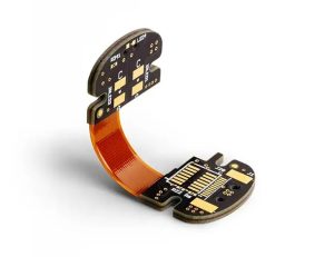
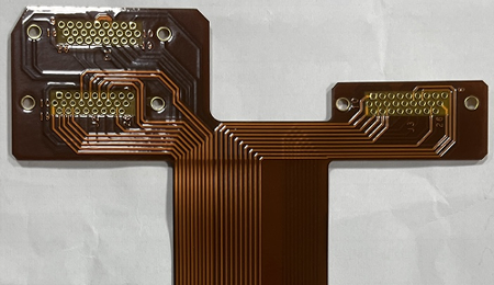
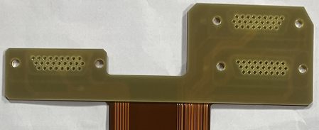
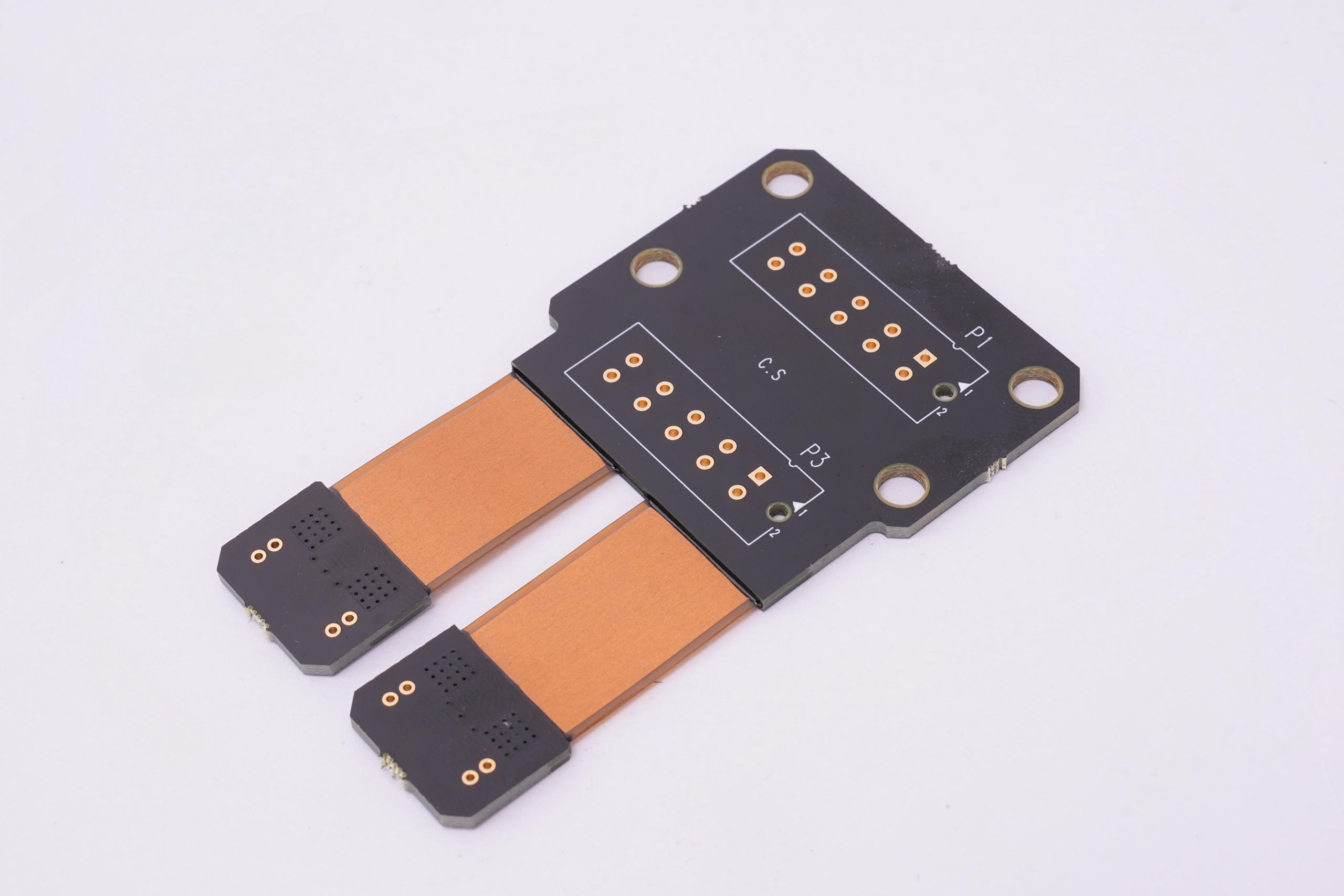
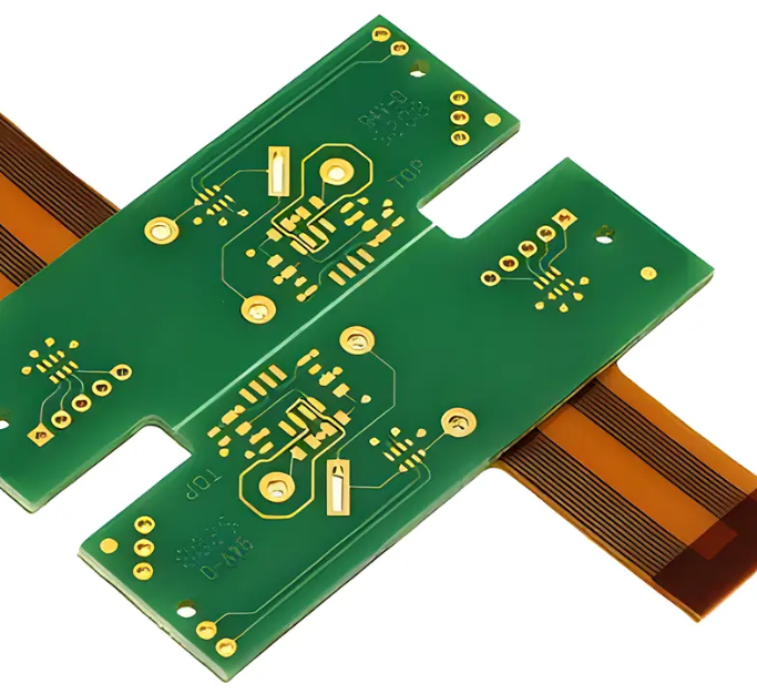
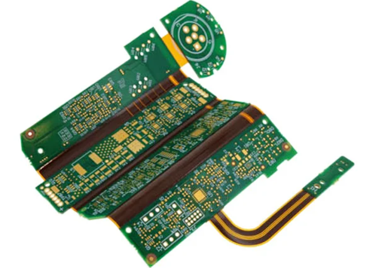
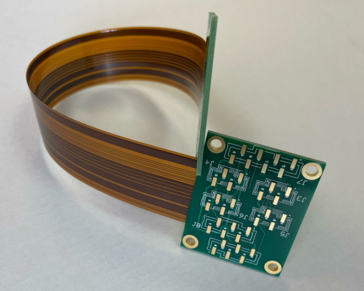
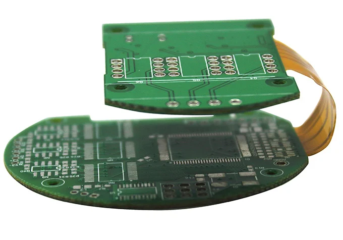
Rigid flex circuit is a PCB structure that combines rigid board sections and flexible circuit layers into one integrated unit. It offers the strength of rigid FR4 boards and the space-saving advantage of flexible circuits. Compared with a standard flex PCB with stiffeners, a true rigid flex board is built with plated through holes (PTH) that electrically connect the rigid and flexible layers inside the structure.

Rigid flex PCBs are widely used in medical devices, aerospace electronics, industrial controls, automotive systems, and advanced consumer products where stable performance and compact structure are required.

What Is a Rigid Flex Circuit?

A rigid flex circuit is a hybrid PCB made by laminating rigid substrates and flexible substrates into one board structure. The rigid sections support component mounting, while the flexible sections allow bending or folding during installation.

This design helps engineers reduce assembly size, simplify internal wiring, and improve product reliability. Instead of using multiple separate boards connected by cables or connectors, a rigid flex PCB combines these functions into one integrated interconnection platform.

Main Features of Rigid Flex PCB

  • Combines rigid and flexible substrates in one board
  • Uses plated through holes for internal electrical interconnection
  • Supports compact and three-dimensional assembly design
  • Reduces connectors, cables, and manual soldering points
  • Improves reliability in high-vibration and limited-space applications
Rigid Flex Circuit

Rigid Flex Circuit

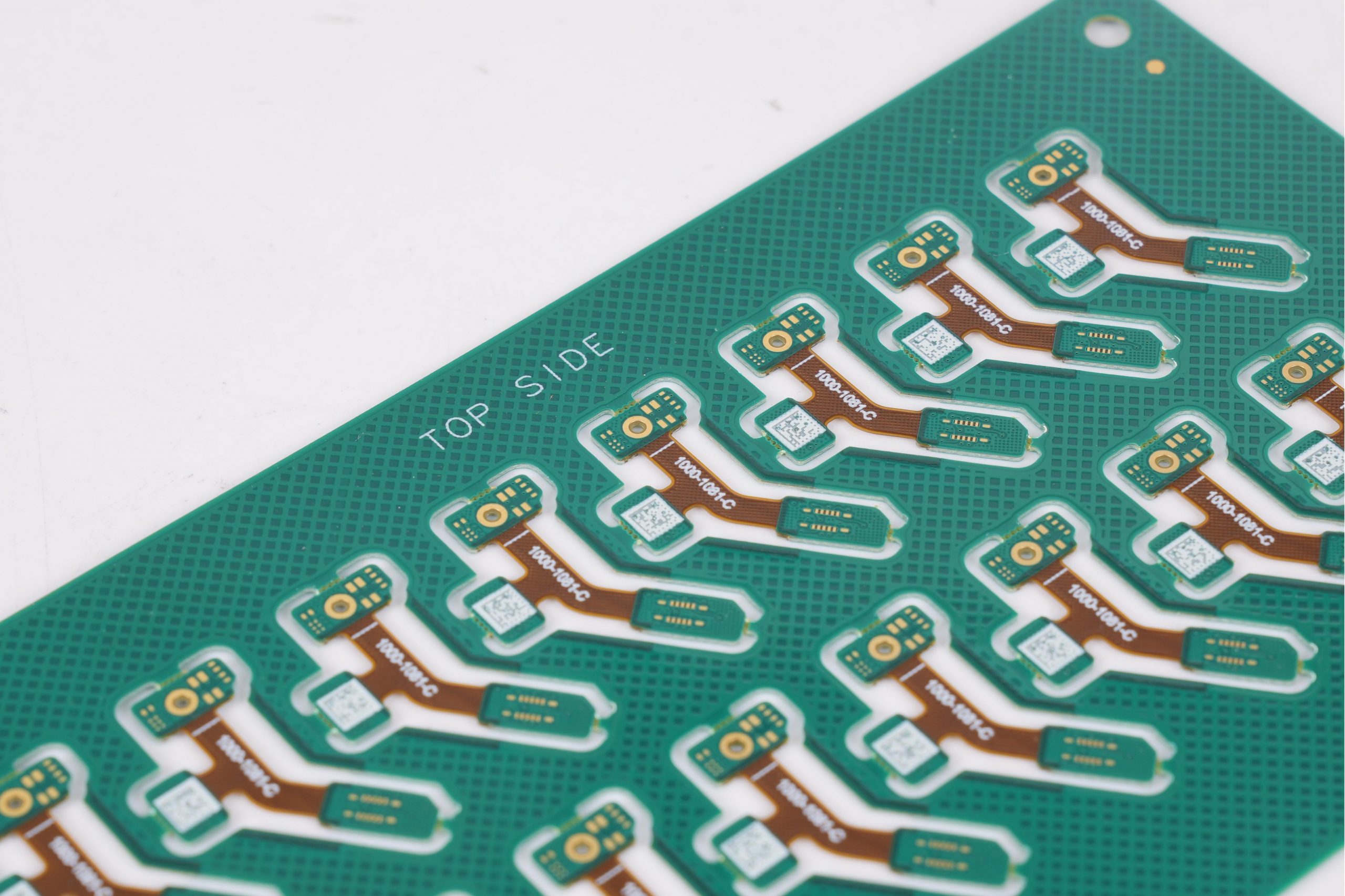
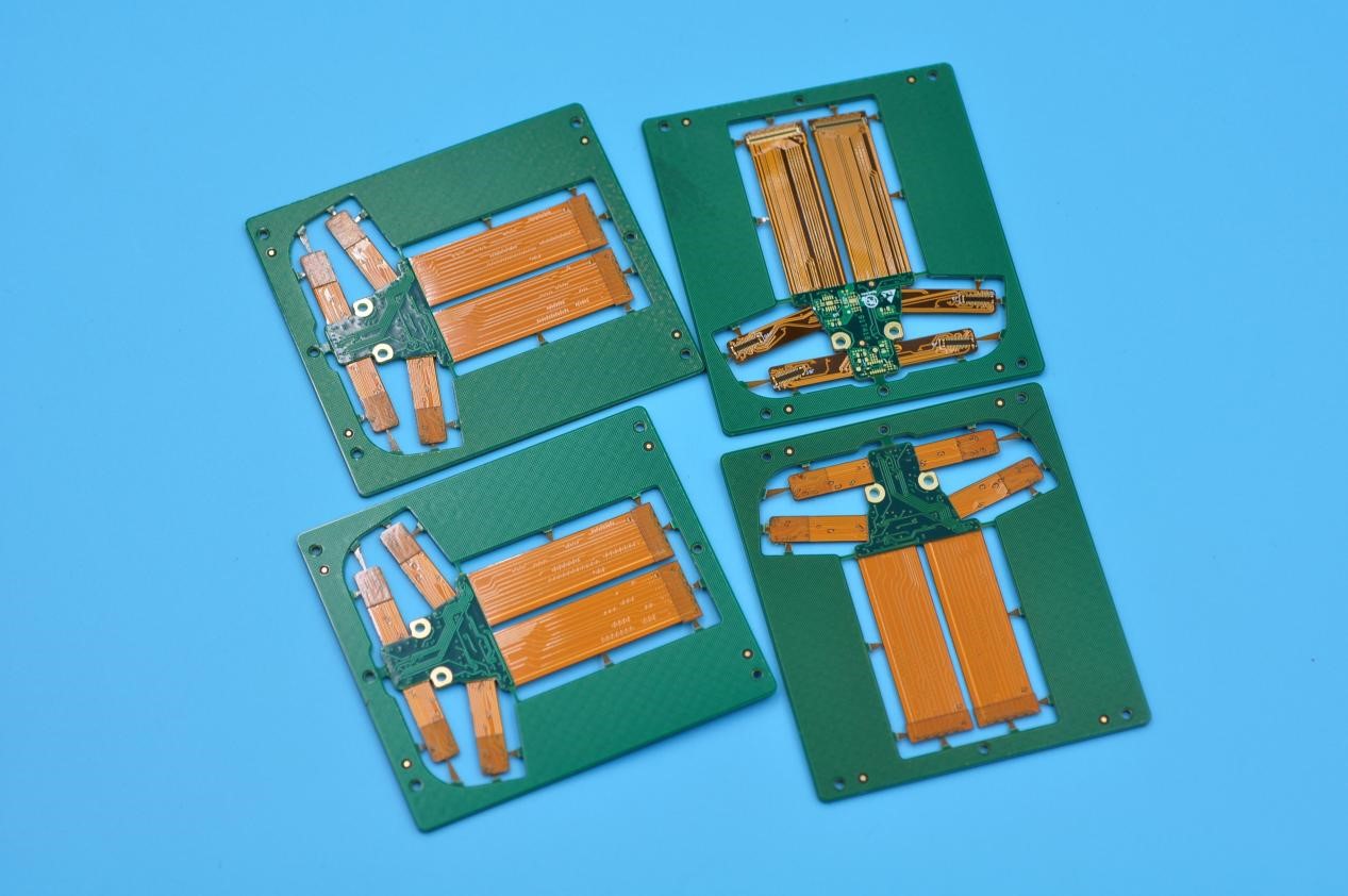
Our Typical Project Cases

Case 1 – Medical Portable Monitoring Device Rigid Flex PCB

Application: Portable medical monitoring system

Board Type: 6 Layer Rigid Flex PCB

Material: FR4 + Polyimide

Surface Finish: ENIG

Key Requirement: Compact size, stable signal, high reliability

Medical Portable Monitoring Device Rigid Flex PCB

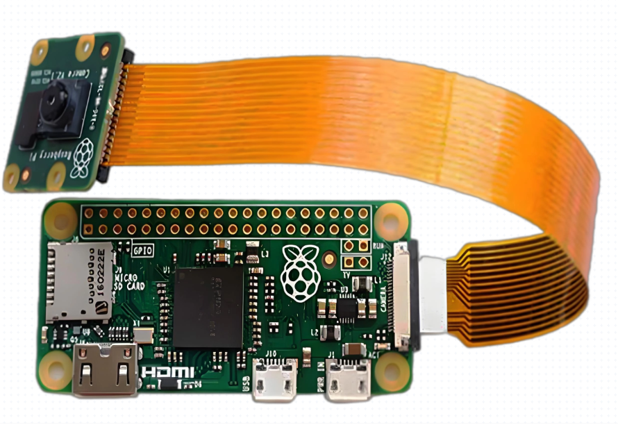
Case 2 – Automotive Camera Module Rigid Flex PCB

Application: Automotive camera system

Board Type: 4 Layer Rigid Flex PCB

Material: High Tg FR4 + Polyimide

Surface Finish: ENIG

Key Requirement: Vibration resistance, compact structure

Automotive Camera Module Rigid Flex PCB

Case 3 – Industrial Control System Rigid Flex PCB

Application: Industrial control module

Board Type: 8 Layer Rigid Flex PCB

Material: FR4 + Polyimide

Surface Finish: ENIG

Key Requirement: High density routing, stable interconnection

Industrial Control System Rigid Flex PCB

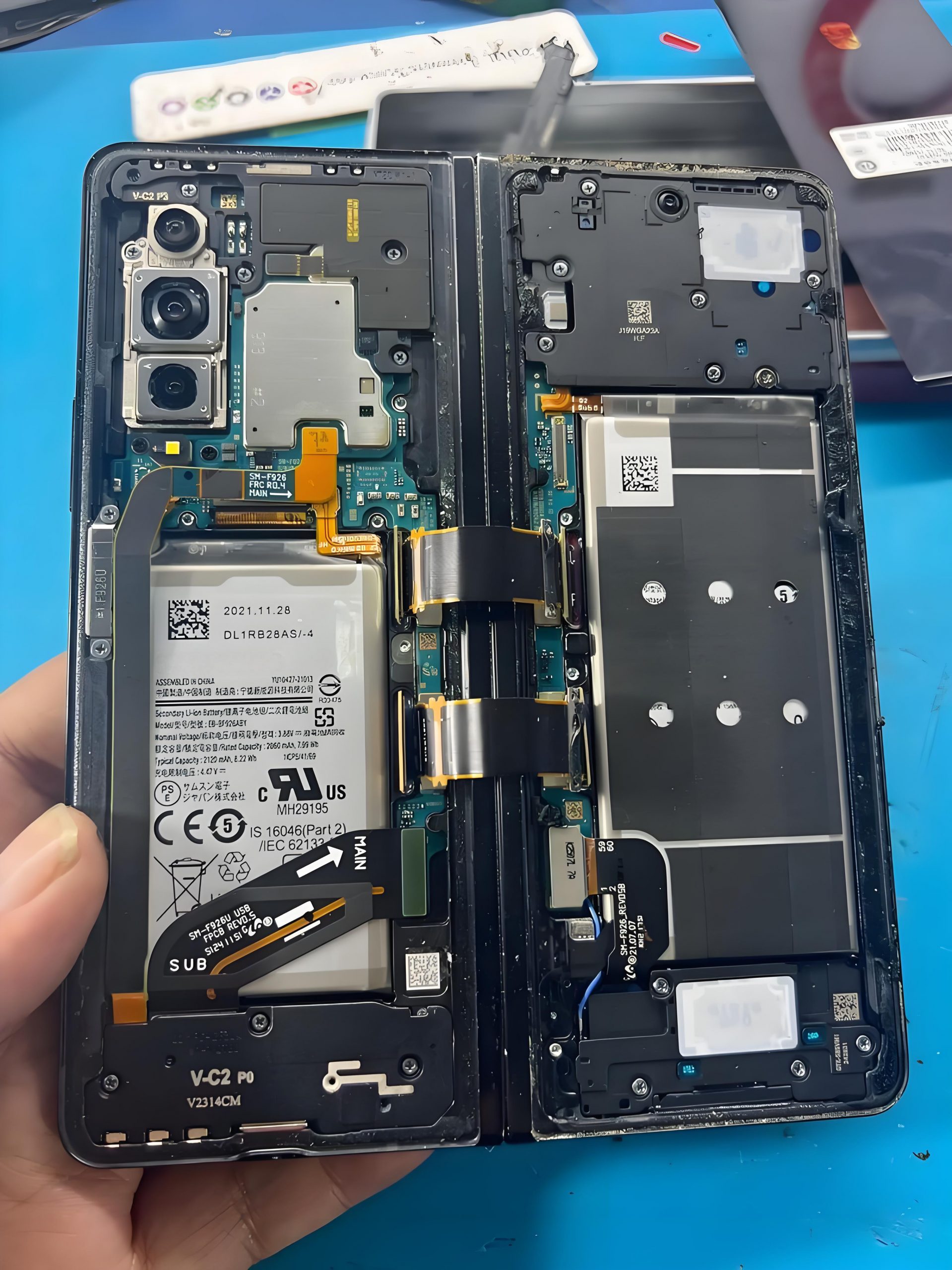
Case 4 – Consumer Electronics Folding Device Rigid Flex PCB

Application: Foldable consumer electronic device

Board Type: 4 Layer Rigid Flex PCB

Material: FR4 + Polyimide

Surface Finish: ENIG

Key Requirement: Repeated bending, compact layout

Consumer Electronics Folding Device Rigid Flex PCB

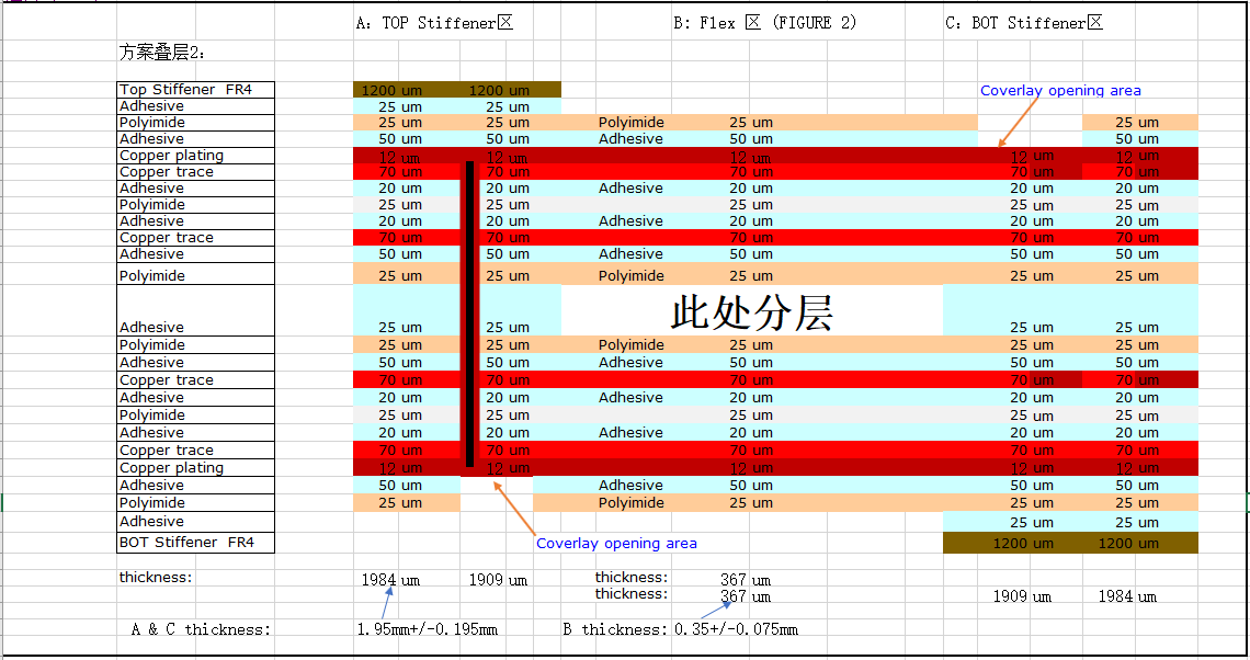
Rigid Flex PCB vs. Flex PCB with Stiffener

A rigid flex circuit is different from a flex PCB with FR4 or polyimide stiffeners.

In a flex PCB with stiffener, the stiffener is added only for local support. It is usually attached by adhesive and does not provide plated electrical interconnection between layers.

In a rigid flex PCB, the rigid and flexible sections are laminated into one complete structure, and the layers are electrically connected through plated through holes. This gives the board stronger structural integrity and better long-term reliability.

Key Difference

ItemRigid Flex CircuitFlex PCB with Stiffener
StructureIntegrated rigid and flex laminateFlex circuit with added support layer
Electrical InterconnectionYes, through plated holesNo plated interconnection through stiffener
Mechanical StabilityHigherModerate
Assembly IntegrationBetterLimited
Typical UseHigh-reliability compact productsLocal reinforcement only

Our Rigid Flex PCB Manufacturing Capabilities

Below is a typical reference table for custom rigid flex PCB manufacturing capability.

ParameterTypical Capability
Rigid Flex StructureSingle-sided, double-sided, multilayer rigid flex
Base MaterialsFR4 + Polyimide
Layer Count2L to 50L
Rigid Layer MaterialStandard FR4 / High Tg FR4
Flexible Layer MaterialPolyimide (PI)
Copper Thickness0.5 oz to 4 oz
Board ThicknessCustom build-up
Flex ThicknessBased on stack-up design
Min Line / Space4/4 mil
Min Drill Hole0.2 mm
Surface FinishENIG, HASL, OSP, Immersion Tin, Immersion Silver
Solder MaskGreen, Black, White, Red, Blue, Yellow
CoverlayYellow / Black / White
Stiffener OptionFR4, PI, Stainless Steel
Impedance ControlSupported
Via TypePTH, blind via, buried via, microvia based on design
Assembly ServicePCB fabrication + SMT assembly
Production TypePrototype to mass production
Assembly SupportSMT, THT, mixed technology assembly
File SupportGerber, drill file, stack-up, assembly drawing, BOM

Common Rigid Flex Stack-Ups

Rigid flex PCB structures are usually designed as multilayer constructions. The final stack-up depends on routing density, bend radius, thickness target, and mechanical design requirements.

4 Layer Rigid Flex

Option 1

  • 1L FR4
  • 2L FPC
  • 1L FR4

Option 2

  • 2L FR4
  • 2L FPC

6 Layer Rigid Flex

Option 1

  • 2L FR4
  • 2L FPC
  • 2L FR4

Option 2

  • 1L FR4
  • 4L FPC
  • 1L FR4

8 Layer Rigid Flex

Option 1

  • 2L FR4
  • 4L FPC
  • 2L FR4

Option 2

  • 1L FR4
  • 6L FPC
  • 1L FR4

Option 3

  • 2L FPC
  • 4L FR4
  • 2L FPC

Option 4

  • 1L FPC
  • 6L FR4
  • 1L FPC

Special Rigid Flex Structures for Custom Applications

Besides standard multilayer designs, some projects require custom rigid flex configurations for special packaging or functional needs.

2 Layer Rigid Flex

  • 1L FR4
  • 1L FPC

3 Layer Rigid Flex

Option 1

  • 1L FR4
  • 1L FPC
  • 1L FR4

Option 2

  • 1L FPC
  • 1L FR4
  • 1L FPC

These special designs are often used in compact electronic modules where a simple but integrated board structure is needed.

Design and Manufacturing Considerations

A reliable rigid flex PCB depends not only on layout, but also on manufacturability planning. Early engineering review can help avoid cracking, delamination, poor bend performance, and assembly issues.

Key Points to Consider

  • Stack-up design between rigid and flex areas
  • Bend radius and bending direction
  • Copper balancing in flex zones
  • Coverlay opening design
  • Stiffener placement
  • Hole location near bend areas
  • Final thickness control
  • Component placement on rigid sections only
  • Impedance and signal path planning for high-speed designs

A good rigid flex supplier should review these details before production, not after problems appear.

Typical Applications of Rigid Flex PCB

  • Medical monitoring and portable diagnostic devices
  • Aerospace and defense electronics
  • Industrial control systems
  • Automotive electronic modules
  • Cameras and optical devices
  • Consumer electronics with compact internal layouts

Why Work With EBest Circuit (Best Technology) for Rigid Flex PCB?

EBest Circuit provides custom rigid flex PCB manufacturing for projects that require compact structure, stable interconnection, and reliable quality. With over 20 years of PCB experience, we support customers from design review to fabrication and assembly.

What We Offer

  • Custom rigid flex PCB fabrication
  • Stack-up review and DFM support
  • PCB and PCBA one-stop service
  • Prototype and volume production support
  • Material and process suggestion based on application
  • Fast response for RFQ and engineering questions

Our engineering team understands the practical challenges behind rigid flex structures and helps customers improve both design feasibility and production stability.

What Files Are Recommended for RFQ?

To speed up quotation and technical review, it is helpful to provide:

  • Gerber files
  • Drill files
  • Stack-up information
  • Fabrication drawing
  • Assembly drawing
  • BOM list
  • Pick and place file if assembly is needed

Clear documentation helps reduce back-and-forth communication and improves quote accuracy.

FAQs

1. What is the minimum bend radius for rigid flex PCB?

The bend radius depends on the flex thickness and copper structure. A common guideline is:

  • Single-layer flex: 6–10 × thickness
  • Double-layer flex: 10–15 × thickness
  • Multilayer flex: 15–20 × thickness

Proper bend radius design is critical to prevent copper cracking or delamination during use.

2. Can components be placed on the flexible area?

In most cases, components should be mounted only on the rigid sections.

Placing components on flex areas is possible in special designs, but it requires careful reinforcement, controlled bending conditions, and additional manufacturing considerations. For standard designs, keeping components on rigid areas improves reliability and assembly stability.

3. What materials are used in rigid flex PCB?

Rigid flex circuits typically use:

  • Rigid layers: FR4 or high Tg FR4
  • Flexible layers: Polyimide (PI)
  • Coverlay: Polyimide film with adhesive
  • Stiffeners: FR4, PI, or stainless steel

Material selection depends on temperature requirements, bending cycles, and electrical performance.

4. How many bending cycles can a rigid flex PCB withstand?

The bending life depends on the design and materials. With proper design, rigid flex circuits can withstand thousands to millions of bending cycles.

Key factors include:

  • Copper thickness
  • Flex layer structure
  • Bend radius
  • Material quality

Engineering optimization is important for applications requiring repeated movement.

Get a Quote for Your Rigid Flex Circuit Project

Looking for a reliable rigid flex PCB manufacturer for your next project? Best Technology can support your design with engineering review, custom stack-up guidance, and stable production service.

Send your Gerber files, stack-up details, or project requirements to sales@bestpcbs.com for quotation and technical support.

You may also like

2oz Thicker Copper Rigid-Flex PCB Manufacturing & Challenges
Wednesday, December 31st, 2025

Recently, Best Technology faced a huge challenge in a 2oz copper rigid flex PCB manufacturing, this board appeared simple on the drawing but revealed multiple layers of engineering challenges once entering mass production. But finally, we finished this project very well and overcome this challenge, let’s see what are the challenges on this project and how does our team overcome them!

Project Introduction

The board used a 70/25 double-sided adhesive ED flexible substrate with PI25/AD50 coverlay, coupled with a 2+2 layers dual access structure that required thick copper, small annular rings, narrow spacings, and FR4 stiffeners with extremely limited clearance. Each of these parameters independently creates difficulty, but combined, they demand precise collaboration between engineering, fabrication, and process control.

This article explains:

  • Why the design was inherently difficult
  • What manufacturing risks were present
  • How our engineering team solved each challenge
  • What PCB designers should avoid in similar projects
  • Why Best Technology can manufacture such high-reliability rigid-flex PCBs

Material Structure and Key Design Parameters

The board consisted of the following:

  • Flexible substrate: 70/25 double-sided adhesive ED copper
  • Coverlay: PI 25 µm + Adhesive 50 µm
  • Base copper: 2 oz copper
  • Layer count: Four-layer rigid-flex structure
  • Critical routing: 0.15 mm minimum trace/space
  • Plated hole: 0.66 mm with hole spacing of only 0.60 mm
  • Annular ring: 0.05 mm on certain pads
  • Stiffener: FR4 stiffener with 0.95 mm stiffener hole and 0.31 mm ribs
Material Structure and Key Design Parameters

This combination is common in advanced HDI rigid-flex PCB manufacturing, yet its manufacturability depends heavily on copper behavior, adhesive flow, and drilling tolerances.

Why This Rigid-Flex PCB Was Inherently Difficult?

1. Thick copper increases side-etching risk

    With 2 oz copper, the etching rate is higher and lateral etch—often called side-etch—is harder to control. In this case, the side-etching amount reached: 0.0070 ± 0.003 mm. For ultra-fine traces in a rigid-flex PCB design, this will eat into the design margin.

    2. Small annular rings compromise via reliability

    Pads with 0.05 mm annular ring severely restrict drilling tolerance. In flex-rigid PCB fabrication, annular rings below 0.10 mm are classified as high-risk features.

    Why This Rigid-Flex PCB Was Inherently Difficult?

    3. Extremely tight stiffener clearance

    The stiffener needed:

    • ±0.20 mm placement tolerance
    • ±0.05 mm drilling tolerance

    But the designer only left 0.15 mm clearance, causing a mismatch between rigid-flex PCB stiffener alignment tolerance and actual manufacturing capability.

    4. Thin FR4 stiffener ribs cause glue overflow

    Ribs only 0.31 mm wide cannot allow adhesive to retreat during bonding, causing pure glue to overflow and block the stiffener holes.

    Why This Rigid-Flex PCB Was Inherently Difficult?

    Technical Challenge #1: Thick Copper Etching with Narrow Spacing

    A 2 oz thick copper PCB combined with:

    • 0.15 mm trace/space
    • 0.05 mm annular ring
    • 0.66 mm PTH

    creates a situation where compensation is unavoidable.

    However, after compensation (~0.007 mm), the remaining trace width would drop to:

    0.08 mm (0.15 – 0.07 mm)

    This is below the safe manufacturability range of most rigid-flex PCB suppliers.

    Best Technology’s solution

    • Eliminated compensation on 0.15 mm traces
    • Implemented fine-tuned etching control
    • Maintained ~0.10 mm final copper width
    • Ensured full electrical reliability

    This is a proven strategy in advanced rigid-flex PCB manufacturing for thick-copper builds.

    Technical Challenge #2: Annular Ring Integrity in Plated Through Holes

    Annular rings <0.10 mm are extremely vulnerable to:

    • Drill wander
    • Etching undershoot
    • Copper thinning

    This is especially critical in high-reliability rigid-flex PCBs, where via integrity is essential.

    Best Technology’s solution

    • Applied rigid-board-level PTH plating process
    • Improved copper thickness inside the via barrel
    • Adjusted drilling control to 0.65 ± 0.075 mm
    • Customer accepted partial ring breakage as long as electrical integrity remained intact

    This ensured consistent via performance even in ultra-dense rigid-flex PCB layouts.

    rigid flex pcb

    Technical Challenge #3: Stiffener Bonding, Alignment, and Adhesive Overflow

    1. Why stiffener tolerance was problematic

    In rigid-flex PCB assembly, stiffeners are critical for mechanical reinforcement. However:

    • Hole spacing was only 0.60 mm
    • Stiffener clearance only 0.15 mm per side
    • Combined tolerance ±0.25 mm

    This inevitably leads to the stiffener covering the pads unless advanced alignment controls are used.

    rigid flex pcb with stiffener

    2. Why glue overflow occurs

    Thin ribs (0.31 mm) cannot provide an escape path for adhesive. During lamination:

    • The glue squeezes into the holes
    • Holes become blocked
    • Boards fail inspection

    3. Best Technology’s engineered solution

    • Pre-laminated pure adhesive onto FR4 stiffener
    • Re-drilled stiffener holes after bonding
    • Greatly reduced glue overflow
    • Added 100% AOI + manual inspection for hole clearing
    • Rejected defective boards, shipped only fully passing units

    This is a common best practice in flex PCB stiffener processing when tolerances are tight.

    DFM Guidelines for Rigid-Flex PCB Designers

    1. Avoid annular rings under 0.15 mm, especially in 2 oz copper flex-rigid PCB design.
    2. Avoid combining thick copper with fine lines, this will increase manufacturing risk.
    3. Ensure stiffener clearance > total tolerance stack-up. If your clearance is smaller than the alignment tolerance, the stiffener will inevitably shift.
    4. Keep stiffener ribs ≥0.5 mm
    5. Send your design for DFM review before finalizing. A good rigid-flex PCB manufacturer will help adjust the stack-up, drill size, and stiffener layout to avoid expensive redesigns.

    This case demonstrates how a complex rigid-flex PCB—with 2 oz copper, ultra-fine traces, small annular rings, and extreme stiffener constraints—can be successfully manufactured through detailed engineering, advanced process control, and disciplined quality screening.

    Best Technology combines strong fabrication capability with practical DFM insight, enabling customers to produce compact, reliable, and manufacturable rigid-flex PCB designs that perform consistently under demanding conditions.

    If you need support with your next rigid-flex or flex PCB project, our engineering team is ready to assist with stack-up review, DFM checks, or trial builds.

    You may also like

    What is a rigid flex pcb? Rigid-flex PCB manufacturer
    Monday, February 24th, 2025

    Rigid-flex PCB is a circuit board that combines rigid board and flexible board. It has both the stability of rigid board and the bendability of flexible board. It is suitable for complex spatial layout and dynamic connection needs and is widely used in consumer electronics, automobile, medical, aerospace and other fields.

    What is a rigid flex pcb? Rigid-flex PCB manufacturer

    What is rigid flex PCBs?

    Rigid-flex PCBs are an advanced type of printed circuit board that combines the best features of rigid and flexible PCBs into a single, seamless design. These boards consist of multiple layers of rigid and flexible substrates interconnected to create a durable, space-efficient, and highly reliable circuit solution.

    Unlike traditional rigid PCBs, which are made of FR4 material, rigid-flex PCBs incorporate flexible layers that allow bending and folding without losing electrical functionality.

    This hybrid design makes rigid-flex PCBs ideal for compact, high-performance electronic devices. They are widely used in aerospace, medical devices, military applications, consumer electronics, and industrial automation.

    By eliminating the need for connectors and cables between rigid sections, these boards enhance reliability, reduce assembly complexity, and improve overall product performance.

    What are the types of PCBs?

    Printed circuit boards come in various types, each designed for specific applications. The most common types include rigid PCBs, flexible PCBs (FPCs), rigid-flex PCBs, single-layer PCBs, multilayer PCBs, and high-frequency PCBs.

    Rigid PCBs are the most widely used type, featuring a solid, non-bendable structure made from fiberglass-reinforced epoxy (FR4). They provide mechanical stability and are commonly found in consumer electronics, automotive systems, and industrial equipment.

    Flexible PCBs, in contrast, are made from polyimide or PET materials, allowing them to bend and twist to fit into tight spaces. They are commonly used in wearable devices, foldable smartphones, and medical sensors.

    Rigid-flex PCBs combine both rigid and flexible elements, offering the benefits of both in a single board. They are particularly useful in applications where space is limited, and durability is crucial.

    Other specialized types include metal-core PCBs for high-heat applications, ceramic PCBs for high-frequency circuits, and HDI PCBs for compact, high-density designs.

    What are the advantages of rigid flex PCB?

    Rigid-flex PCBs offer numerous advantages, making them the preferred choice for high-reliability applications. Their primary benefit is the ability to combine rigid and flexible circuits, reducing the need for additional connectors and wiring.

    Another key advantage is space efficiency. Rigid-flex PCBs allow engineers to design compact, lightweight products without sacrificing performance.

    What is a rigid flex pcb? Rigid-flex PCB manufacturer

    By folding or bending the flexible sections, these boards can fit into complex enclosures, making them ideal for portable and miniaturized devices. Additionally, their reduced weight and material usage lower manufacturing and assembly costs.

    Durability is another major strength. With fewer connectors and solder joints, rigid-flex PCBs are more resistant to mechanical stress, vibrations, and environmental factors. This makes them perfect for applications in aerospace, automotive, and military industries, where reliability is non-negotiable.

    What are the disadvantages of rigid flex PCB?

    While rigid-flex PCBs offer many advantages, they also come with some challenges. One of the main drawbacks is the higher manufacturing cost compared to standard rigid or flexible PCBs.

    The complex design and fabrication process require specialized materials, and advanced equipment, leading to increased production expenses. However, this cost is often offset by the benefits of improved reliability and reduced assembly time.

    Another challenge is the design complexity. Unlike standard PCBs, rigid-flex boards require precise layout planning, including bending radius calculations, flexible section reinforcement, and controlled impedance routing.

    Manufacturing yield rates can also be lower due to the intricate layering and bonding processes involved. Any misalignment or material defects during production can impact the board’s functionality. To ensure high-quality results, working with an experienced rigid-flex PCB manufacturer is essential.

    What is the difference between rigid-flex and semi-flex?

    Rigid-flex and semi-flex PCBs serve different purposes. Rigid-flex PCBs are fully integrated designs with both rigid and flexible sections permanently bonded together. These boards can bend repeatedly without damage, making them suitable for applications requiring continuous movement or folding.

    Semi-flex PCBs, on the other hand, are designed for limited bending. They are typically made from a partially flexible FR4 substrate that can bend a few times during installation but is not meant for continuous flexing.

    What is a rigid flex pcb? Rigid-flex PCB manufacturer

    Semi-flex boards are often used in products where a single bend is needed to fit the PCB into an enclosure, such as industrial control panels and certain automotive systems.

    While both types improve space efficiency and reduce connectors, rigid-flex PCBs provide greater versatility for dynamic applications. Semi-flex PCBs offer a cost-effective alternative when only minimal bending is required.

    What is the difference between FPC and rigid-Flex?

    Flexible PCBs (FPCs) and rigid-flex PCBs share similarities but differ in their structural composition and usage.

    FPCs are fully flexible circuits with no rigid sections, designed to bend and twist in any direction. They are commonly used in applications requiring extreme flexibility, such as foldable smartphones, medical sensors, and wearable devices.

    Rigid-flex PCBs, in contrast, combine rigid and flexible layers. The rigid sections provide mechanical support for components, while the flexible sections allow for movement and space optimization. This hybrid approach is beneficial for complex assemblies where both strength and flexibility are needed, such as aerospace control systems and military-grade electronics.

    When to use rigid-flex pcb?

    Rigid-flex PCBs are ideal for applications where space constraints, reliability, and durability are critical. They are commonly used in aerospace and defense electronics, where weight reduction and high reliability are essential.

    Medical devices, such as pacemakers and imaging equipment, also benefit from rigid-flex PCBs due to their compact size and long-term reliability.

    Consumer electronics, including foldable smartphones, smartwatches, and VR headsets, leverage rigid-flex PCBs to create lightweight, compact designs.

    Additionally, automotive applications use them in advanced driver-assistance systems (ADAS) and infotainment systems to ensure consistent performance under extreme conditions.

    Industries that require rugged, high-performance electronics can greatly benefit from rigid-flex PCB technology. The ability to withstand harsh environments, reduce assembly complexity, and enhance product longevity makes them a smart choice for advanced electronic designs.

    What is an example of a rigid-flex PCB?

    One of the best examples of rigid-flex PCB applications is in foldable smartphones. These devices require flexible circuits to accommodate screen folding while maintaining uninterrupted electrical connections. The integration of rigid and flexible sections enables compact, lightweight designs without sacrificing durability.

    What is a rigid flex pcb? Rigid-flex PCB manufacturer

    Another example is in aerospace control panels. Rigid-flex PCBs help reduce wiring complexity in cockpit instruments, ensuring high reliability in extreme environments.

    Similarly, medical implants like pacemakers use rigid-flex PCBs to achieve a compact form factor while maintaining long-term reliability inside the human body.

    Military-grade electronics, such as communication devices and guidance systems, also rely on rigid-flex PCBs. Their ability to withstand vibrations, temperature fluctuations, and high mechanical stress makes them a preferred choice for mission-critical applications.

    Conclusion:

    Rigid-flex PCBs offer a powerful combination of flexibility, durability, and space efficiency. They eliminate the need for connectors, reduce wiring complexity, and improve reliability, making them ideal for high-performance applications.

    For high-quality rigid-flex PCB manufacturing, EBest Circuit (Best Technology) offers expert solutions tailored to your needs. Contact us at sales@bestpcbs.com to discuss your project.

    You may also like