PCB manufacturing PCB manufacturing
Home > Blog

power factor

Watts to Amps Calculator: DC, AC and Three-Phase Formulas
Wednesday, August 5th, 2026

Watts to amps conversion requires the power in watts, the voltage at the same point in the circuit, and the circuit type. For DC, current equals watts divided by volts. Single-phase and three-phase AC calculations may also require power factor, while a conversion based on output power must account for efficiency. Use the calculator and formulas below to obtain a current value, then verify nameplate limits, startup current and conductor or PCB requirements separately.
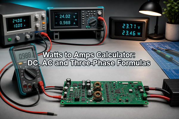
Watts to Amps Calculator: DC, AC and Three-Phase Formulas

What Does Watts to Amps Mean?

Watts to amps means calculating electrical current from known real power and voltage. Watts measure the rate of energy transfer, amps measure current, and volts describe the electrical potential that drives that current. Because the same power can be delivered at different voltages, one wattage does not correspond to one universal amperage.

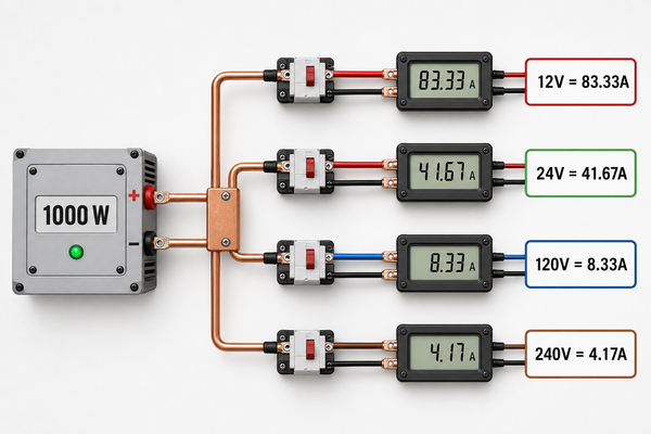
For example, a 120 W DC load draws 10 A at 12 V but only 0.5 A at 240 V. The power is unchanged, yet the low-voltage path carries twenty times more current. That difference affects wiring, connectors, fuses, copper losses and PCB conductor design.

How to Convert Watts to Amps?

To convert watts to amps, identify the wattage, voltage and whether the circuit is DC, single-phase AC or balanced three-phase AC. For AC, obtain the power factor from the equipment datasheet or nameplate. If the listed wattage is useful output power rather than electrical input power, include conversion efficiency.

  1. Use power and voltage measured or specified at the same side of the circuit.
  2. Select the formula for DC, single-phase AC or three-phase AC.
  3. Enter power factor for AC equipment instead of assuming it is always 1.
  4. Set efficiency to 100% when the wattage is already input power.
  5. Calculate the steady-state current, then check surge and maximum nameplate current separately.

How Does the Watts to Amps Calculator Work?

The calculator selects the correct current equation for the circuit type and applies power factor and efficiency only where they belong. Three-phase mode assumes a balanced load and line-to-line voltage. If the entered watts are electrical input power, leave efficiency at 100%; if they are output power, enter the expected conversion efficiency.


Result: 8.33 A

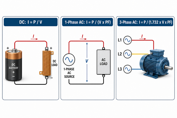
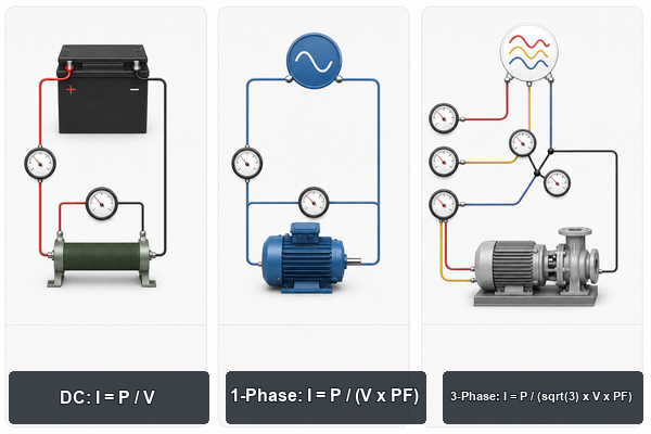
DC single-phase AC and three-phase watts to amps formulas

What Is the Watts to Amps Formula for DC?

For DC input power, use I = P / V, where I is current in amps, P is power in watts and V is voltage in volts. A 500 W load at 24 V therefore draws 20.83 A in the ideal calculation.

If 500 W is converter output power and efficiency is 90%, estimate source current with I = Pout / (V x efficiency). At 24 V, the input current becomes 500 / (24 x 0.90) = 23.15 A. For batteries, repeat the calculation at the minimum operating voltage because current rises as voltage falls.

What Is the Watts to Amps Formula for Single-Phase AC?

For single-phase AC real power, use I = P / (V x PF). A 1000 W resistive load at 120 V and PF 1 draws 8.33 A, while a 1000 W load at PF 0.80 draws 10.42 A.

Power factor and efficiency describe different effects. Power factor relates real power in watts to apparent power in volt-amperes; efficiency relates useful output power to electrical input power. If the entered wattage is output power, a practical estimate may require both: I = Pout / (V x PF x efficiency).

What Is the Watts to Amps Formula for Three-Phase AC?

For a balanced three-phase load using line-to-line voltage, use I = P / (sqrt(3) x VLL x PF). A 5000 W load at 400 V and PF 0.90 draws 8.02 A before any efficiency correction.

When phase-to-neutral voltage is used, the balanced-load equation is I = P / (3 x VLN x PF). Do not mix line-to-line and line-to-neutral voltage in the same formula. Unbalanced equipment requires phase-by-phase evaluation rather than the balanced shortcut.

What Is the Difference Between Watts, Amps and Volts?

Watts describe power, amps describe current and volts describe electrical potential. The three quantities are related, but they are not interchangeable units.

Quantity Unit What it describes Basic DC relation
Power Watt (W) Energy transferred per unit time P = V x I
Current Ampere (A) Rate of electric charge flow I = P / V
Voltage Volt (V) Electrical potential difference V = P / I

In AC systems, the simple product V x I gives apparent power when waveform and phase effects are present. Real power in watts also depends on power factor, which is why the equipment nameplate may list volts, amps, watts and VA separately.

What Is the Watts to Amps Conversion at 12V, 24V and 48V?

At low DC voltage, current increases rapidly as power rises. The table uses I = P / V and assumes the wattage is input power with no additional conversion loss.

Power 12 V DC 24 V DC 48 V DC
100 W 8.33 A 4.17 A 2.08 A
500 W 41.67 A 20.83 A 10.42 A
1000 W 83.33 A 41.67 A 20.83 A
2000 W 166.67 A 83.33 A 41.67 A

These are steady-state arithmetic values. A 12 V inverter delivering 1000 W of AC output will draw more than 83.33 A from the battery because the inverter is not 100% efficient and battery voltage can sag under load.

What Is the Watts to Amps Conversion at 120V, 220V and 240V?

For a resistive single-phase AC load with PF 1, divide watts by the supply voltage. Loads with a lower power factor draw more RMS current than this table shows.

Power 120 V AC 220 V AC 240 V AC
100 W 0.83 A 0.45 A 0.42 A
500 W 4.17 A 2.27 A 2.08 A
1000 W 8.33 A 4.55 A 4.17 A
2000 W 16.67 A 9.09 A 8.33 A
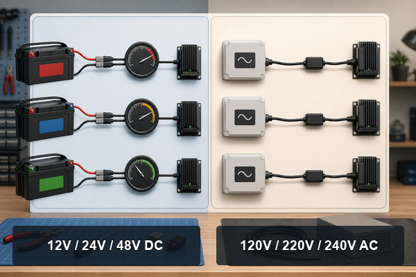
Watts to amps values at low-voltage DC and common AC voltages

For dedicated values and additional assumptions, see the existing 1000 and 1500 watts to amps guide. Keeping those fixed-power examples on their own page prevents the general calculator from repeating the same material.

How Does Power Factor Change Watts to Amps?

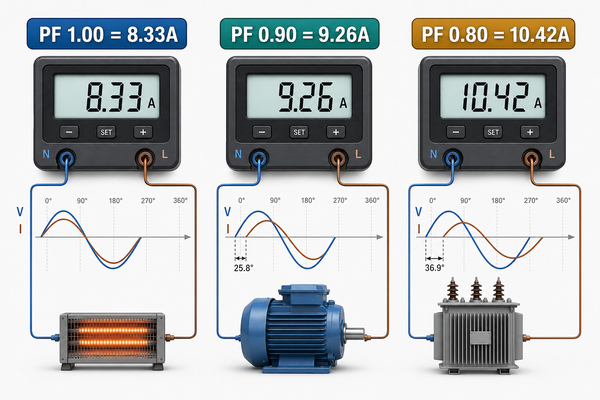
A lower power factor increases AC current for the same real power and voltage. At 120 V, a 1000 W load draws 8.33 A at PF 1, 9.26 A at PF 0.90 and 10.42 A at PF 0.80.

Use the power factor specified for the operating condition. Motors may have different values at startup and partial load, while switch-mode power supplies with power-factor correction can behave differently from units without it. If a nameplate gives VA rather than W, divide VA by voltage to estimate current instead of treating VA as real power.

How Do Efficiency and Inverter Losses Change Current?

Efficiency raises the required input current when the known wattage is output power. A 1000 W inverter with 90% efficiency requires about 1111 W of DC input. At 12 V, that equals 92.59 A before voltage sag, cable loss and no-load consumption are added.

Calculate each side of a converter separately. The 120 V AC output current for a 1000 W resistive load is 8.33 A, but the 12 V battery input current can exceed 90 A. The watts remain in the same range, while the current changes because the voltage changes and losses must be supplied upstream.
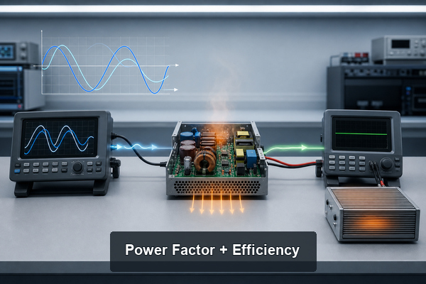
Power factor and inverter efficiency effects on watts to amps

Why Can Measured Current Differ from the Calculated Value?

Measured current differs when the calculation omits operating conditions that exist in the real circuit. Nameplate tolerances, voltage variation, power factor, conversion loss, load duty cycle and instrument bandwidth can all move the reading.

  • Startup current: motors, transformers and capacitive inputs can draw a short surge above steady-state current.
  • Changing load: controllers and switch-mode supplies may pulse or vary their input current.
  • Voltage sag: lower source voltage produces more current when the load maintains constant power.
  • Measurement method: distorted AC waveforms require a suitable true-RMS instrument.
  • Input versus output rating: an output wattage cannot be divided by input voltage without including efficiency.

Use the formula as an estimate and compare it with the maximum nameplate current and measurements at minimum voltage, full load and startup. Protective devices and conductors must be selected from the applicable standard and equipment requirements, not from one ideal conversion alone.

How Do Watts to Amps Calculations Affect PCB Design?

The calculated current is an input to PCB design, not a complete trace-width rule. Copper thickness, layer location, trace length, allowable temperature rise, ambient temperature, airflow, via arrays, terminal resistance and duty cycle determine how the current path should be implemented.

Low-voltage power stages can require wide conductors, copper pours, busbars or a heavy copper PCB. High-power LED and converter assemblies may use a metal core PCB when heat spreading is a central requirement. Complete PCB assembly validation must also consider power-device packages, connectors, solder joints, fuses and current sensing.
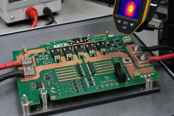
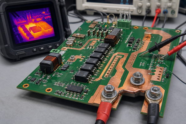
High-current PCB copper paths after a watts to amps calculation

EBest Circuit (Best Technology) lists Extreme Heavy Copper PCB capability up to 200 OZ, subject to material selection, layer stack-up, board dimensions, design complexity, quantity and engineering review. Available verification processes include copper thickness testing, while PCBA inspection can include AOI, X-ray, functional testing and final inspection. These checks validate the manufactured current path; they do not replace electrical and thermal design calculations.

What Common Watts to Amps Mistakes Should Be Avoided?

The most common errors come from choosing incomplete inputs or applying a correct formula to the wrong circuit type.

  • Converting watts without specifying voltage.
  • Using the DC equation for an AC load with power factor below 1.
  • Using the single-phase formula for a three-phase system.
  • Mixing line-to-line and line-to-neutral voltage.
  • Using output watts as input watts without an efficiency correction.
  • Confusing amps with amp-hours, which measure current and charge capacity respectively.
  • Ignoring surge current, minimum supply voltage or current-limit behavior.
  • Using the calculated current as the final breaker, cable, connector or PCB rating.

FAQ About Watts to Amps

1. How many amps is 100 watts?

One hundred watts equals 8.33 A at 12 V DC, 4.17 A at 24 V DC, 0.83 A at 120 V and 0.42 A at 240 V when PF is 1. For AC equipment with a lower power factor, divide by voltage and power factor.

2. What is 20 amps in watts?

Multiply current by voltage. Twenty amps equals 240 W at 12 V, 2400 W at 120 V and 4800 W at 240 V for DC or a resistive PF 1 load. For AC real power, multiply volts by amps and power factor.

3. Is 1 amp 1000 watts?

No. One amp equals 12 W at 12 V, 120 W at 120 V and 240 W at 240 V under the simple DC or PF 1 relation. Reaching 1000 W at 1 A would require 1000 V under that same assumption.

4. How to convert watts to amps 240V?

For DC or a resistive single-phase 240 V load, divide watts by 240. A 1000 W load equals 4.17 A and a 2000 W load equals 8.33 A. For AC equipment, include power factor and use the correct phase formula.

Conclusion

Accurate watts to amps conversion starts with the correct voltage and circuit type. DC uses I = P / V, single-phase AC adds power factor, and balanced three-phase AC adds the sqrt(3) factor when line-to-line voltage is used. Efficiency, startup current and minimum voltage explain why measured or upstream current can be higher than the ideal result. For power PCB fabrication and assembly support after the electrical requirements are defined, contact EBest Circuit (Best Technology) at sales@bestpcbs.com.

You may also like

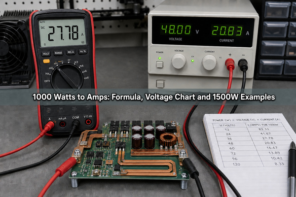
1000 Watts to Amps: Formula, Voltage Chart and 1500W Examples
Wednesday, July 22nd, 2026

1000 watts to amps is not one fixed value because current depends on voltage and circuit type. At 120 V with a power factor of 1, 1000 W equals 8.33 A; at 240 V it equals 4.17 A; and at 12 V DC it equals 83.33 A. This guide gives the corresponding 1500 W results, the correct formulas for DC and AC systems, and the limits that must be checked before using a calculated current for a breaker, conductor, connector, or PCB trace.

1000 watts to amps conversion with power supply, multimeter and PCB

How Many Amps Is 1000 Watts?

At 120 V, 1000 watts is 8.33 amps when the load is DC or a purely resistive single-phase AC load. The same 1000 W equals 83.33 A at 12 V, 41.67 A at 24 V, 9.09 A at 110 V, 4.55 A at 220 V, 4.35 A at 230 V, and 4.17 A at 240 V.

The simple calculation is current = power / voltage, or I = P / V. For an AC motor, transformer, or switching power supply, divide by power factor as well. A lower power factor produces a higher current for the same real power.

How Many Amps Is 1500 Watts?

At 120 V and power factor 1, 1500 watts equals 12.5 amps. It equals 125 A at 12 V DC, 62.5 A at 24 V DC, 13.64 A at 110 V, 6.82 A at 220 V, 6.52 A at 230 V, and 6.25 A at 240 V.

These values describe the current associated with 1500 W under the stated electrical conditions. The device nameplate may show a different input current if the advertised wattage is output power, if conversion efficiency is below 100%, or if an AC load has a power factor below 1.

Why Can’t Watts Be Converted to Amps Without Voltage?

Watts measure power, while amps measure current, so voltage is required to connect the two quantities. One thousand watts can be delivered as high current at low voltage or lower current at high voltage. For example, 1000 W requires 83.33 A at 12 V but only 4.17 A at 240 V when no other correction factor applies.

This distinction matters because current, rather than wattage alone, drives conductor heating, connector contact loss, fuse selection, voltage drop, and PCB copper requirements. Always identify the operating voltage at the same point in the system where the current will be evaluated.

How to Convert Watts to Amps?

Identify the real power in watts, the operating voltage, and whether the circuit is DC, single-phase AC, or three-phase AC. For AC loads, obtain the power factor from the nameplate or datasheet. Then select the matching formula and keep all values in watts, volts, and amperes.

  1. Confirm whether the listed wattage is input power or output power.
  2. Use the actual operating voltage, not only the nominal system label.
  3. Select the DC, single-phase AC, or three-phase AC equation.
  4. Include power factor and efficiency when the rating requires them.
  5. Compare the result with the equipment nameplate and measured current.
1000 watts to amps formula for common voltage values

What Is the Watts-to-Amps Formula for DC Circuits?

For a DC load whose input power is known, use I = P / V. A 1000 W load on a 24 V DC bus therefore draws 41.67 A in the ideal calculation: 1000 / 24 = 41.67.

If 1000 W is the converter’s output power rather than its input power, include efficiency. At 24 V and 90% efficiency, the estimated input current is I = Pout / (V x efficiency), so 1000 / (24 x 0.90) = 46.30 A. Battery voltage also changes with state of charge and load, so minimum operating voltage is often the more demanding design point.

What Is the Watts-to-Amps Formula for Single-Phase AC?

For single-phase AC real power, use I = P / (V x PF), where PF is power factor. A 1000 W resistive heater at 120 V and PF 1 draws 8.33 A. A 1000 W load at 120 V and PF 0.80 draws 10.42 A.

Do not substitute efficiency for power factor. Power factor describes the relationship between real power and apparent power, while efficiency describes losses between input and useful output. A motor or power converter calculation may require both, depending on which power rating is supplied.

What Is the Watts-to-Amps Formula for Three-Phase AC?

For a balanced three-phase load using line-to-line voltage, use I = P / (sqrt(3) x VLL x PF). For 1500 W at 400 V and PF 0.85, the line current is 1500 / (1.732 x 400 x 0.85) = 2.55 A.

This equation assumes a balanced system and uses line-to-line voltage. If the available specification uses phase voltage, or if the load is unbalanced, calculate the phases according to the actual connection and verify each conductor rather than applying the balanced shortcut.

DC single-phase AC and three-phase watts to amps formulas

What Is the 1000 Watts to Amps Chart at Common Voltages?

The table below uses I = 1000 / V. It is exact for DC input power and for a single-phase resistive AC load with PF 1; other AC loads require a power-factor correction.

Voltage Calculation Current at 1000 W Typical context
12 V 1000 / 12 83.33 A Battery, automotive, low-voltage inverter input
24 V 1000 / 24 41.67 A Battery bank, control or mobile power system
48 V 1000 / 48 20.83 A Telecom, battery storage, DC distribution
110 V 1000 / 110 9.09 A Nominal AC supply
120 V 1000 / 120 8.33 A North American single-phase supply
220 V 1000 / 220 4.55 A Nominal AC supply
230 V 1000 / 230 4.35 A Common international single-phase supply
240 V 1000 / 240 4.17 A Single-phase appliance or equipment circuit

What Is the 1500 Watts to Amps Chart at Common Voltages?

The same calculation applied to 1500 watts to amps produces the following ideal values. Use the AC formulas above when power factor is not 1.

Voltage Calculation Current at 1500 W
12 V 1500 / 12 125.00 A
24 V 1500 / 24 62.50 A
48 V 1500 / 48 31.25 A
110 V 1500 / 110 13.64 A
120 V 1500 / 120 12.50 A
220 V 1500 / 220 6.82 A
230 V 1500 / 230 6.52 A
240 V 1500 / 240 6.25 A

How Does Power Factor Change the Amp Calculation?

A lower power factor increases RMS current for the same real power and voltage. At 120 V, a 1000 W load draws 8.33 A at PF 1, 9.26 A at PF 0.90, and 10.42 A at PF 0.80. The additional current affects conductor loss, connector heating, protective-device loading, and upstream component ratings.

Use the power factor specified for the operating condition. Motors can have different values at startup and partial load, while electronic power supplies may use power-factor correction. If only apparent power in volt-amperes is provided, current is VA divided by voltage; do not treat VA and W as interchangeable.

Power factor effect on watts to amps current calculation

Can 15 Amps Handle 1000 Watts?

At 120 V, a 1000 W resistive load draws about 8.33 A, so it is below a 15 A circuit’s nominal current rating. At 110 V it draws about 9.09 A. The complete circuit load still matters: other devices on the branch circuit, continuous-operation rules, wiring method, ambient temperature, connector ratings, and local electrical code can reduce the usable margin.

For a continuous load, some codes apply an 80% loading rule, which corresponds to 12 A on a 15 A circuit. That is not a universal permission to select a breaker from wattage alone. Verify the equipment nameplate and use the requirements of the governing code and a qualified electrical professional.

What Size Breaker Do I Need for 1500 Watts?

A 1500 W resistive load draws 12.5 A at 120 V, 13.64 A at 110 V, and 6.25 A at 240 V. On a 120 V system, 12.5 A exceeds the 12 A continuous-load level associated with an 80% limit on a 15 A circuit, so a properly designed 20 A branch circuit is commonly considered for continuous operation.

The breaker must protect the installed conductors and must match the equipment, receptacle, load duration, startup current, and local code. Do not replace a breaker with a higher rating unless the entire circuit is designed for that rating. For heaters and other high-duty loads, the nameplate and installation instructions take priority over a generic conversion.

How Do Watts-to-Amps Calculations Affect PCB Design?

The calculated current is an input to PCB conductor and interconnect design, but it is not the finished trace-width specification. Copper thickness, external or internal layer placement, allowable temperature rise, trace length, ambient temperature, airflow, terminal resistance, via arrays, duty cycle, and current sharing all change the result.

High-current PCB copper paths and thermal inspection for a 1000 watt power design

A 1000 W converter can present very different board challenges on its low-voltage and high-voltage sides. A 12 V, 1000 W path may exceed 80 A before efficiency losses, while a 240 V path carries only a few amperes but requires greater clearance and insulation coordination. Review high-current PCB construction, heavy copper PCB for power electronics, and custom PCB power supply layout as separate but connected design decisions.

Before release, validate current paths with the appropriate trace-current method, copper build, thermal model, connector data, fuse behavior, and temperature testing. EBest Circuit (Best Technology) can review PCB fabrication and assembly details against the actual stackup and current path rather than treating the wattage conversion as a complete design rule.

What Common Watts-to-Amps Mistakes Cause Wrong Results?

Most wrong answers come from using the correct arithmetic with the wrong electrical inputs. Check the rating context before trusting the result.

  • Missing voltage: watts alone cannot determine current.
  • Wrong circuit formula: DC, single-phase AC, and three-phase AC are not interchangeable.
  • Assuming PF 1: inductive and many electronic loads draw more current than the resistive calculation.
  • Confusing input and output power: conversion losses increase upstream input current.
  • Using nominal voltage only: battery and supply voltage can vary under load.
  • Ignoring startup or surge current: motors, transformers, heaters, and capacitive inputs can briefly draw more than steady-state current.
  • Mixing W and kW: convert 1 kW to 1000 W before applying the formula.
  • Treating the result as a component rating: breakers, wire, connectors, fuses, and PCB traces require additional design checks.

FAQ About 1000 and 1500 Watts to Amps

1. How many amps does it take to run a 1500 watt electric heater?

A 1500 W resistive heater draws 12.5 A at 120 V, 13.64 A at 110 V, 6.52 A at 230 V, or 6.25 A at 240 V. Confirm the heater nameplate because controls, fans, and nominal voltage can change the listed input current.

2. How many amps is 1500 watts DC?

Divide 1500 W by the DC voltage. The result is 125 A at 12 V, 62.5 A at 24 V, and 31.25 A at 48 V. If 1500 W is output power, divide by efficiency as well when estimating source current.

3. How many watts can a 20 amp breaker handle?

The arithmetic maximum is voltage multiplied by current: 2400 W at 120 V or 4800 W at 240 V. Usable continuous power may be lower under applicable code, and the breaker must match the conductor, receptacle, equipment, and installation.

4. How many watts is a 15-amp load?

At PF 1, 15 A corresponds to 1800 W at 120 V and 3600 W at 240 V. A continuous-load limit, other loads on the circuit, and power factor can reduce the permitted real power.

5. Is 1 amp always the same number of watts?

No. One amp equals 12 W at 12 V, 120 W at 120 V, and 240 W at 240 V when PF is 1. Watts always depend on both current and voltage, plus power factor for applicable AC calculations.

Conclusion

The correct 1000 watts to amps result is 8.33 A at 120 V, 4.17 A at 240 V, or 83.33 A at 12 V under the simple PF 1 calculation. For 1500 W, the corresponding values are 12.5 A, 6.25 A, and 125 A. Always confirm voltage, circuit phase, power factor, efficiency, and whether the wattage is an input or output rating before selecting electrical or PCB hardware. For PCB fabrication and PCBA support around power and high-current designs, contact EBest Circuit (Best Technology) at sales@bestpcbs.com.

You may also like