





Resistor tolerance can determine whether a voltage divider, current-sense channel, or other precision circuit remains within its intended operating range. For PCB and PCBA buyers, the real risk is not only receiving the wrong nominal resistance; it is approving a component whose permitted variation, temperature behavior, or substitute specification exceeds the circuit’s error budget.
This guide helps you calculate the allowed resistance range, verify color bands and SMD ordering codes, review BOM and datasheet requirements, control substitutions, and define the inspection or test evidence needed before production. If you need support with BOM review, approved component sourcing, PCBA, inspection, or test coordination, contact EBest Circuit (Best Technology) at sales@bestpcbs.com.
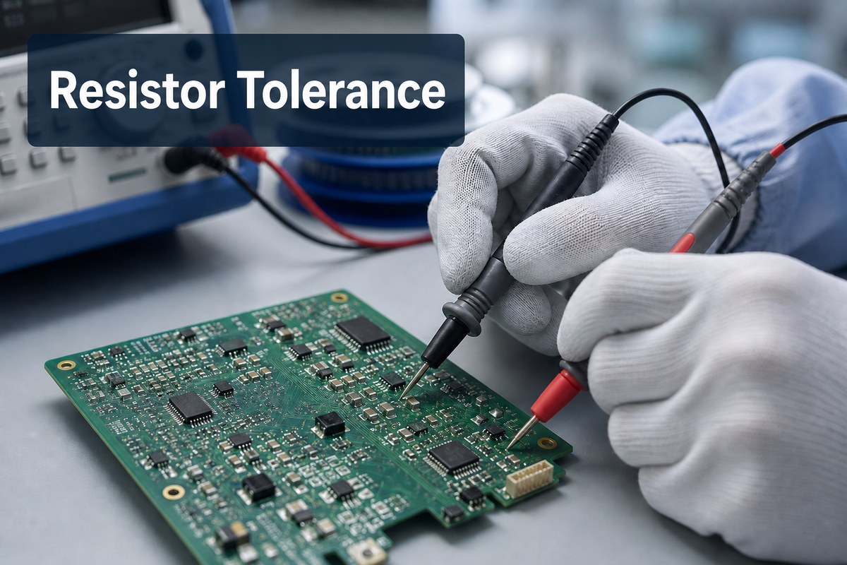
What Does Tolerance in Resistance Mean for PCB Buyers?
Tolerance in resistance is the permitted difference between a resistor’s nominal value and its actual resistance at the stated reference conditions. A 10 kOhm resistor with a tolerance of +/-1% is permitted to measure from 9.9 kOhm to 10.1 kOhm before other effects are considered.
That percentage is a manufacturing limit, not a promise that every part will be offset by the same amount. One production lot may cluster close to nominal, while another approved lot can sit elsewhere inside the specified band. A prototype measurement that happens to be near nominal does not justify replacing a 1% part with a 5% part.
For a buyer, tolerance should be treated as a controlled BOM characteristic alongside:
- nominal resistance;
- package and termination style;
- rated power and working voltage;
- temperature coefficient of resistance, usually stated in ppm/degree C;
- pulse or overload capability;
- technology, such as thick film, thin film, metal film, or wirewound;
- qualification, environmental, and traceability requirements.
The percentage matters most when the circuit depends on the absolute resistance or on the ratio between multiple resistors. Examples include feedback networks, current sensing, gain setting, voltage dividers, reference paths, filters, timing networks, and bias circuits. It may matter less in a pull-up whose acceptable range is broad, but that conclusion must come from the circuit requirements rather than from a generic purchasing rule.
The useful procurement outcome is a BOM line that identifies the required tolerance unambiguously and an approved manufacturer part number whose datasheet confirms it.
How to Calculate Resistance Tolerance and Its Allowed Range
The basic calculation converts the tolerance percentage into an absolute deviation:
Allowed deviation = Nominal resistance x Tolerance percentage / 100
Minimum resistance = Nominal resistance – Allowed deviation
Maximum resistance = Nominal resistance + Allowed deviation
For a 4.7 kOhm resistor with +/-5% tolerance:
- Allowed deviation = 4,700 Ohm x 5 / 100 = 235 Ohm
- Minimum resistance = 4,700 Ohm – 235 Ohm = 4,465 Ohm
- Maximum resistance = 4,700 Ohm + 235 Ohm = 4,935 Ohm
For the same nominal value at +/-1%, the permitted range becomes 4,653 Ohm to 4,747 Ohm. That narrower band may protect circuit performance, but it can also affect component cost, availability, technology choice, and the number of qualified substitutes.
Buyers should avoid using the nominal tolerance range as the entire error analysis. The delivered resistance can also shift with temperature, self-heating, aging, mounting stress, humidity, and measurement conditions. Contact resistance and fixture accuracy can distort low-ohmic measurements, while ordinary handheld instruments may not provide enough accuracy to accept or reject a tight-tolerance part.
Before turning the formula into an incoming-inspection limit, confirm:
- the datasheet conditions under which initial tolerance is specified;
- the measurement temperature and stabilization time;
- whether lead or contact resistance must be compensated;
- the required instrument accuracy and calibration status;
- whether the customer’s acceptance limit includes guard banding;
- whether the check is intended to verify identity, screen a lot, or prove circuit performance.
A calculated range is valuable because it exposes ambiguity early. It should not be mistaken for a complete reliability or functional-test specification.
Tolerance on Resistors: Color Bands and Letter Codes
Tolerance on resistors can be shown by color bands, printed letters, part-number suffixes, packaging labels, or manufacturer-specific ordering codes. The correct reading method depends on the resistor construction and the manufacturer’s documentation.
For common axial resistors, the separated tolerance band is often read after the significant-digit and multiplier bands. Frequently encountered colors include:
- brown: +/-1%;
- red: +/-2%;
- green: +/-0.5%;
- blue: +/-0.25%;
- violet: +/-0.1%;
- gray: +/-0.05%;
- gold: +/-5%;
- silver: +/-10%;
- no tolerance band on some older three-band parts: typically +/-20%.
Letter codes are also common in ordering systems. Typical IEC-style tolerance letters include F for +/-1%, G for +/-2%, J for +/-5%, K for +/-10%, and M for +/-20%. Tighter classes can use letters such as B, C, or D, but the manufacturer’s datasheet and part-number structure remain the controlling evidence.
Color alone is not enough for production purchasing. Lighting, contamination, body color, band spacing, and human color perception can cause mistakes. A photograph of a loose component is weaker evidence than the original reel label, supplier certificate, manufacturer part number, and current datasheet revision.
Use markings as an identification check, then reconcile them with the controlled BOM and receiving records. If the marking conflicts with the label or datasheet, quarantine the material until the discrepancy is resolved. Do not instruct the assembly line to “use it because the measured value looks close.”
What Does 5% Tolerance on a Resistor Mean?
A 5% tolerance means the initial resistance may be as much as 5% above or below the nominal resistance at the specified reference conditions. It does not mean the resistor will drift by 5% during use, and it does not automatically mean the part has lower power capability or poorer reliability than a 1% resistor.
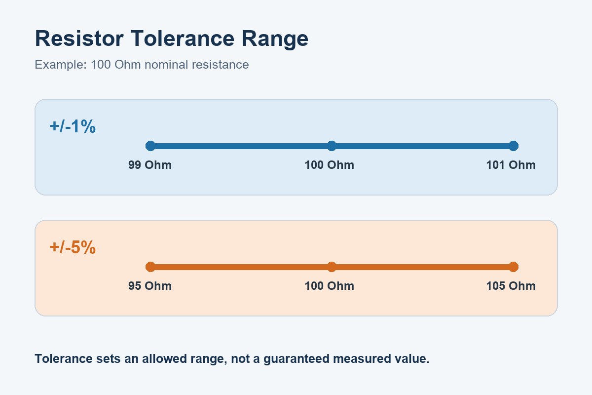
For example, a nominal 100 Ohm, +/-5% resistor can initially measure from 95 Ohm to 105 Ohm. A nominal 100 Ohm, +/-1% resistor has an initial range of 99 Ohm to 101 Ohm.
Whether 5% is acceptable depends on the circuit consequence at both limits. The engineering review should examine the worst-case output, not just the resistance difference. A wider tolerance can change:
- divider voltage and threshold margin;
- amplifier gain or filter response;
- LED or bias current;
- current-sense accuracy;
- timing or oscillator behavior;
- power dissipation in the resistor and connected parts;
- production-test limits and false-failure rates.
A 1% part is not automatically sufficient for a precision function. Two nominally 1% resistors used as a ratio can create a larger worst-case ratio error if their deviations move in opposite directions. Matched networks or ratio-tolerance specifications may be more appropriate when tracking matters. Temperature coefficient and long-term stability can also dominate after the initial tolerance requirement is met.
The buyer’s decision should therefore be tied to the approved part number and circuit requirement. If a distributor proposes a 5% substitute for a 1% BOM line, similarity in nominal resistance and package does not make the substitution acceptable. Engineering approval is required before purchasing or assembly.
SMD Resistor Tolerance: What to Verify Beyond the Printed Code
SMD resistor tolerance is often difficult or impossible to confirm from the component body alone. Many chip resistors are too small to carry a complete marking, and some approved series are supplied unmarked. A three- or four-digit code usually identifies nominal resistance, not every electrical characteristic.
This makes reel-level and document-level control essential. Before releasing SMD resistors to a feeder, verify:
- manufacturer name and complete manufacturer part number;
- nominal resistance, tolerance, package, power rating, and series;
- lot or date code and quantity;
- supplier identity and traceability documents;
- moisture or storage controls when applicable;
- label consistency between outer packaging, reel, and receiving record;
- current datasheet revision and ordering-code interpretation;
- approved-source and approved-substitute status.
Do not infer tolerance solely from the number of printed digits. A four-digit marking is often associated with a more precise nominal value, but markings vary by manufacturer and package size. The complete ordering code is the safer control point.
Package selection also creates assembly risk. A replacement may share nominal resistance and tolerance yet have different rated power, working voltage, terminal material, thickness, land-pattern recommendation, pulse behavior, or anti-sulfur performance. These differences can affect solder-joint geometry, placement, inspection, field reliability, and compliance with the customer’s environment.
BestPCBS already provides separate guidance on SMD resistor package sizes. Use that dimensional information together with the selected manufacturer’s datasheet; do not treat the package code as a complete electrical specification.
How Resistor Tolerances Change Worst-Case Circuit Performance
Resistor tolerances change circuit results through both absolute-value error and ratio error. The relevant mechanism depends on the topology. Purchasing teams do not need to redesign the circuit, but they do need to recognize when a substitution requires engineering review.
Consider a simple divider with two equal nominal resistors. If the upper resistor moves to its maximum allowed value while the lower resistor moves to its minimum, the output ratio shifts in one direction. Reversing those deviations shifts it in the other direction. An analysis that assumes both resistors drift together can understate the worst case.
Similar interactions appear in:
- operational-amplifier feedback networks, where resistor ratio sets gain;
- shunt current measurement, where resistance error directly affects calculated current;
- pull-up networks, where resistance interacts with leakage and capacitance;
- RC timing and filtering, where both resistance and capacitance tolerances contribute;
- bias networks, where current or operating point can move;
- protection and threshold circuits, where margin may already be narrow.
Initial tolerance is only one contributor. A defensible review may also need temperature coefficient, ambient range, self-heating, long-term drift, voltage coefficient, board contamination, leakage, and the tolerances of other components. For low-resistance shunts, PCB copper and sensing geometry can be part of the measurement error. For high-resistance networks, surface leakage can become important.
The manufacturing handoff should translate the engineering conclusion into controlled fields: exact approved part numbers, explicit tolerance, no-substitute or approval rules, and any test limits. Without that translation, the error analysis can remain correct in the design file while procurement unintentionally releases a wider-tolerance part.
BOM and Datasheet Checks for the Correct Resistor Tolerance Value
The correct resistor tolerance value should appear consistently across the schematic, BOM, approved vendor list, purchase order, supplier quotation, and inspection plan. A mismatch between those files is a revision-control problem even if the material has not yet reached production.
Before requesting a PCBA quotation, provide a BOM that includes, at minimum:
- unique item or reference designation;
- nominal resistance with an unambiguous unit;
- tolerance;
- package or case size;
- rated power and other critical ratings;
- manufacturer and complete manufacturer part number;
- approved alternatives or a clear no-substitution instruction;
- applicable notes, standards, or traceability requirements;
- BOM revision aligned with the released Gerber or ODB++ data, pick-and-place file, and assembly drawing.
Then review the datasheet for the exact ordering code. Family-level tables can contain multiple tolerance options, temperature coefficients, terminal finishes, and package ratings. A distributor title such as “10 kOhm chip resistor” is not enough to confirm the ordered variant.
Approved-substitute review should compare more than nominal value. Ask engineering to confirm tolerance, temperature coefficient, technology, rated power, working voltage, overload behavior, environmental options, dimensions, land pattern, availability, and any application-specific qualification. Record the approval against the exact substitute part number and applicable product revision.
EBest Circuit can flag BOM ambiguity, reconcile purchasing data with released files, and coordinate approved component sourcing. The customer should resolve circuit-performance questions and approve deviations before material is purchased or loaded for assembly.
How to Control Resistance Tolerance During Sourcing and PCBA
Resistance tolerance control begins before the purchase order. Inspection cannot recover a missing requirement that was never defined, and a functional test cannot always identify which BOM parameter caused a failure.
A practical control sequence is:
- Freeze the released BOM and identify tolerance-critical references.
- Confirm exact manufacturer part numbers and approved sources.
- Require documented approval before any substitution.
- Match purchase-order descriptions to the controlled BOM.
- Verify supplier, packaging, labels, lot information, and quantity at receiving.
- Perform risk-based identity or resistance checks with suitable calibrated equipment.
- Maintain reel-to-feeder and lot-to-build traceability where required.
- Verify first-article placement and polarity-independent component identity against the assembly data.
- Run the customer’s approved ICT, flying-probe, functional, or other test plan.
- Preserve inspection and test records with the production lot.
Measurement strategy should match the risk. Sampling resistance may help detect a wrong value or mixed lot, but it may not prove every part meets a tight tolerance. In-circuit measurements can be influenced by parallel paths. Functional testing can confirm product behavior at test conditions but may not demonstrate performance across temperature, input range, aging, or every component corner.
For a critical function, the customer may request additional evidence such as supplier certificates, incoming-inspection data, first-article records, AOI images, test logs, or serial/lot traceability. Each document answers a different question. A certificate supports identity or conformance; AOI supports placement and solder-joint inspection; resistance measurement supports the sampled electrical value; functional testing supports defined board behavior.
Agree on the evidence before production. Retrofitting traceability or reconstructing feeder history after a field complaint is slower, more expensive, and sometimes impossible.
Project Example: Controlling ±1% Printed Resistor Tolerance on a Ceramic PCB
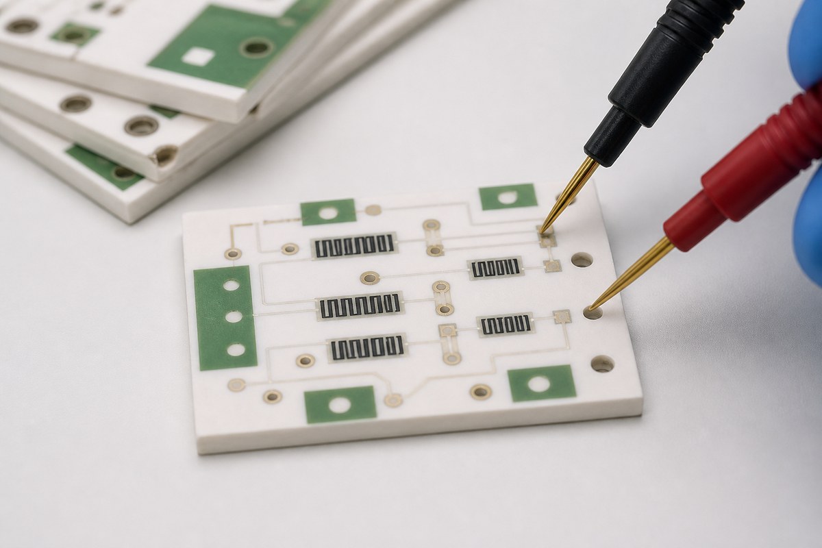
In one anonymized EBest Circuit project, the resistors were printed directly onto a single-sided thick-film ceramic PCB.
Project specifications
- 0.635 mm 96% alumina substrate
- AgPd conductor with 20% palladium
- Green solder mask with no legend
- 12 boards per panel
- Resistance values defined in the customer’s controlled table
- COC and resistance test report required
Revision change
The A0 order included 24 boards plus five spares.
For B0, the board construction remained unchanged. However, the printed resistor tolerance was revised to +/-1%, and the order increased to 1,020 boards plus 12 spares.
The two versions looked similar, but their electrical acceptance limits were different.
Production control
EBest Circuit treated B0 as a new controlled revision. Each printed resistor had to remain within +/-1% of its specified nominal value.
Unlike an SMD resistor, a printed resistor has no reel label or separate manufacturer part number. Its resistance is a finished-board characteristic and must be measured.
Verification evidence
- Visual inspection checked contamination, damaged edges, and printing defects.
- Resistance measurement verified each printed resistor against its allowed range.
- The resistance test report recorded the electrical results.
- The COC confirmed overall order conformity.
Visual inspection could not replace resistance testing, and the COC could not replace measured data.
Project outcome
The B0 revision, +/-1% tolerance, 12-up panel format, and test documentation remained aligned as production increased from a small batch to more than 1,000 boards.
Buyer takeaway
When printed resistor tolerance changes, release a new drawing or product revision. Clearly define:
- each nominal resistance;
- its allowed tolerance;
- measurement conditions;
- inspection coverage;
- test-report requirements.
A ceramic PCB can look identical to an earlier version and still be electrically nonconforming.
FAQs About Resistor Tolerance
Is a 1% resistor always better than a 5% resistor?
No. A 1% resistor has a narrower initial resistance range, but the correct choice depends on circuit requirements, temperature behavior, rated power, pulse capability, cost, availability, and other specifications. Use the approved engineering requirement rather than a universal preference.
Does resistor tolerance include temperature drift?
Usually not. Initial tolerance and temperature coefficient are separate specifications. Temperature coefficient describes how resistance changes with temperature, while initial tolerance describes the permitted value at defined reference conditions. Check the exact datasheet.
Can incoming inspection prove that every resistor meets its tolerance?
Not automatically. The conclusion depends on sampling plan, instrument accuracy, measurement method, environmental conditions, and whether every part or only a sample is tested. Incoming inspection is often most useful for identity and gross-error detection unless a specific acceptance plan is defined.
Can a 5% resistor replace a 1% resistor if the measured sample is within 1%?
No automatic substitution should be made. A sample reading near nominal does not change the manufacturer’s tolerance specification for the lot. Obtain engineering approval for the exact proposed part before purchase or assembly.
What should I send for a resistor-critical PCBA quotation?
Send the released BOM with exact manufacturer part numbers, nominal values, resistor tolerance requirements, packages, ratings, approved alternatives, and revision status. Include assembly data, drawings, test requirements, and any traceability or inspection expectations. For BOM review, component sourcing, PCBA, and test coordination, contact EBest Circuit (Best Technology) at sales@bestpcbs.com.
You may also like






Tags: Printed Resistor Tolerance, Resistor Tolerance, SMD Resistor Tolerance