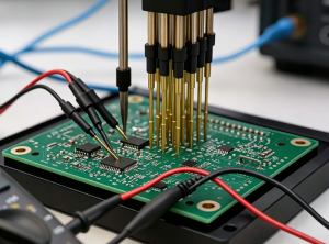
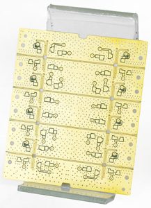
PCB antenna enclosure detuning occurs when the assembled product changes the antenna’s electrical environment enough to shift its response. A plastic wall, battery, screw, cable or changed ground geometry can matter. However, reduced range after closing a case is not proof of detuning: radiation loss, a changed pattern, receiver noise and an uncontrolled test can produce similar symptoms.
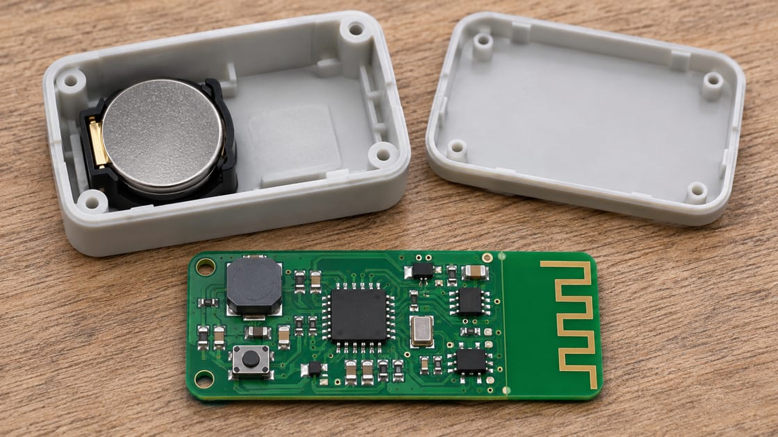
Use a hypothetical battery-powered 2.4 GHz sensor as the running example. It communicates on the bench but becomes unreliable inside its enclosure. The goal is to identify what changed, test that hypothesis and verify the complete assembly. It is not to copy a universal keepout distance or guess a new matching capacitor.
What Changes When the Case Closes?
Closing the case changes the materials and objects surrounding the radiator, and sometimes the positions of the board, battery and cables. The antenna is part of that assembled electromagnetic system, not an isolated copper shape.
Antenova’s detuning discussion describes how nearby conductive parts and enclosure materials can affect the antenna environment. For the sensor, begin with a mechanical comparison: what moves toward the antenna when the lid is secured? A newly routed battery lead is a different suspect from the lid material itself.
Which Antenna Parameters Help Diagnose the Change?
Use measurements that distinguish port matching from radiated performance. A single range number is useful as a symptom, but it does not identify the mechanism.
| Parameter | Meaning | Diagnostic boundary |
| Frequency response | How the antenna behaves across the band | A single point can miss a shifted response |
| S11 | Reflection at a defined reference plane | Does not directly measure radiated efficiency |
| Return loss | Positive loss measure from reflection magnitude | Check sign convention against S11 in dB |
| Radiation efficiency | Radiated fraction of accepted power | Needs suitable radiated measurement |
| Radiation pattern | Direction-dependent response | One orientation is not the entire pattern |
| Packet error result | Link outcome under defined conditions | Also depends on radio and interference |
These are diagnostic quantities, not promised sensor specifications. Record the operating band, setup and device configuration alongside each result.
Detuning vs Absorption vs Receiver Noise
Separate these candidate mechanisms before changing the antenna. More than one can exist in the same product.
| Candidate | Possible observation | Useful next check |
| Impedance detuning | Port response shifts after assembly | Compare calibrated sweeps in both states |
| Loss or shielding | Weak radiated link despite acceptable match | Assess radiated performance and nearby materials |
| Pattern change | Some orientations worsen more than others | Repeat controlled orientation comparisons |
| Receiver noise | Performance changes with internal activity | Compare power and operating modes |
| Test variation | Results move without a design change | Control position, traffic and surroundings |
The table is a diagnostic starting point, not a rule that one observation proves one cause. Preserve the baseline while investigating each hypothesis.
Respect the Radiator Keepout and Its Ground Reference
Follow the actual antenna’s reference layout, including its ground geometry and layer-specific keepout. “Ground is useful” and “no ground beneath this radiator” can both be correct for different parts of a design.
For common monopole-style board antennas, the ground region participates in antenna behavior while the designated radiator area requires its specified clearance. Infineon AN91445, revision H discusses enclosure and ground-plane effects for its illustrated antenna systems. Do not transfer one drawing’s distances to every antenna type. In the sensor review, inspect every copper layer and the assembled mechanical model.
Why Can a Plastic Lid Affect a PCB Antenna?
Nonmetallic does not mean electromagnetically invisible. Material close to the radiator can change its loading, even when it does not fully shield the signal.
The relevant question is not simply “Is the case plastic?” Record the wall position, material and nearby internal features. AN91445 explains how nearby plastic can lower resonance in its discussed antenna context. The direction and magnitude in the sensor still need measurement; do not assign a fixed frequency shift from the material name. Compare the actual production-intent lid rather than assuming a loosely placed prototype cover represents the same geometry.
Check Batteries, Screws, Cables and Coatings
Review all nearby objects as possible contributors, not just the outer wall. Conductive hardware and wiring can change coupling, current paths or radiation behavior.
For the sensor, photograph the cable route and battery position before and after closure. Check whether a mounting screw, shield or metallic coating approaches the antenna region. If one object can be moved in an engineering sample, compare controlled configurations without changing everything else. Do not conclude that a removed screw is unnecessary for the final product; mechanical retention, safety and production requirements still apply. The diagnostic result should inform a reviewed redesign.
Build a Controlled Open-and-Closed Comparison
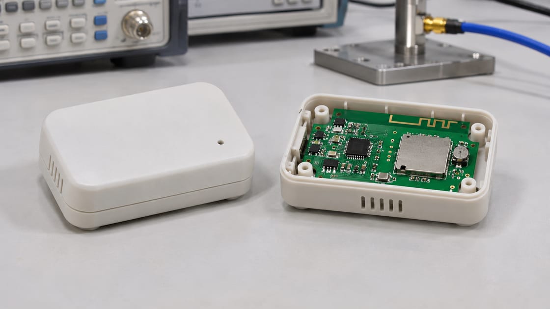
Compare the same radio configuration and physical setup while changing only the assembly state you intend to investigate. Otherwise, a changed result can have several explanations.
Keep firmware, channel, transmit power, battery state, peer device, separation and orientation fixed for an initial comparison. Use a repeatable nonconductive fixture where appropriate and record the environment. Compare more than one unit before deciding the effect is systematic. The hypothetical sensor’s “works on my desk” observation is a useful starting point, but it is not a reproducible acceptance test. Define what constitutes an improvement before trying corrective changes.
Use a VNA with a Defined Reference Plane
A vector network analyzer can compare antenna input response, but the connection and cable become part of the measurement problem. Establish where the calibrated result applies and how the radio is isolated for that measurement.
Use an RF specialist’s suitable fixture and calibration method rather than attaching a cable anywhere convenient. Record its route and keep it consistent between assembly states. A cable that cannot pass through a fully closed lid without changing the geometry may limit the comparison. Treat an observed shift as evidence within that setup, and confirm it with a representative assembled configuration before choosing corrective components.
What Does a Better S11 Actually Prove?
It proves a change in reflection at the measured port under those conditions, not automatically a better radio link. Matching and radiation are related but different.
For a calculated example, S11 = −10 dB corresponds to a reflected-power fraction of 10%, while −6 dB corresponds to about 25.1%, using 10 raised to S11/10. The remainder is accepted at the port; it is not necessarily all radiated. These are mathematical examples, not measured sensor data or universal acceptance limits. A well-matched lossy structure can still perform poorly over the air, so do not stop the investigation at an attractive dip.
Correct the Mechanism Before Guessing Matching Parts
Choose the correction from the evidence: geometry, clearance, component placement, material or matching may need attention. A matching network is not a guaranteed cure for shielding or loss.
TI AN043, revision D is a specific 2.4 GHz PCB antenna reference, not a universal shape that remains unchanged in every host board. Likewise, TE’s embedded-antenna design note discusses ground-plane and tuning limitations. For the sensor, select candidate changes, document them and measure again instead of repeatedly swapping components without a baseline.
Verify the Link in the Final Product Configuration
After correcting the suspected cause, verify radio behavior with the intended enclosure, battery, cable routes and operating modes. The best open-board result is not the delivery configuration.
Use the project’s agreed link criteria and controlled tests across relevant channels, orientations and use conditions. Include internal high-activity modes if they might affect the receiver. Retain the measurement setup and configuration identifiers so another unit can be compared. Check any required radio-compliance implications with the responsible specialist; neither this article nor an improved laboratory response establishes regulatory approval. A range claim requires its own documented conditions.
Freeze the RF-Relevant Mechanical and PCB Details
Release the validated combination, not just the antenna trace artwork. Capture the board outline, stackup, copper keepout, matching population and surrounding mechanical configuration.
The Best Technology PCB antenna manufacturing guide explains why manufacturing handoff matters. Flag a later case, battery or ground change for RF review rather than treating it as purely cosmetic. For a Best Technology fabrication discussion, send the controlled board files and antenna constraints to sales@bestpcbs.com. Any tuning, radiated testing or assembly service must be confirmed within the actual project scope.
FAQ
Can I copy a working antenna into a smaller PCB?
Not with an assumption of unchanged performance. A different board outline and ground region can alter the antenna system even if the radiator artwork is identical. Use the reference design’s complete constraints, then evaluate the actual host board and enclosure. Treat copying as a design starting point rather than validation.
Is there one safe distance between an antenna and every enclosure?
No universal distance covers every antenna, frequency, material and geometry. Use the actual antenna documentation and verify the assembled product. A distance from a particular module guide belongs to that guide’s conditions; it is not a general clearance rule for every trace antenna, chip antenna or external antenna.
Does a metal case always require the same antenna solution?
No. The appropriate solution depends on the complete RF and mechanical design. An external antenna or a deliberately designed RF-transparent region may be considered, but both need engineering evaluation. Do not assume that a small opening, plastic insert or stronger transmitter automatically restores the required coverage and compliance.
Why does touching the unit change its range?
A person’s hand changes the antenna’s nearby environment and may alter both loading and propagation. That makes handling an uncontrolled variable in a bench comparison. Use repeatable fixtures for diagnostic measurements, then include representative handling in the product’s intended-use validation rather than judging performance from one hand-held position.
Can increasing transmit power solve the problem?
It does not identify or correct the underlying mechanism and may not improve the reverse link. It can also affect battery consumption, thermal behavior and regulatory obligations. First determine whether the issue is matching, radiation, interference or the test setup. Use permitted radio settings and validate the complete link.
Why can one channel work while another fails?
The assembled antenna response and the interference environment can vary across frequency. A shifted or narrow response can affect channels differently, but that is not the only explanation. Compare channel-dependent port and link evidence under controlled conditions before attributing the result solely to the antenna or changing its geometry.
Does a pre-certified radio module remove the need for enclosure checks?
No. Follow the module’s integration instructions and the conditions of its approvals, and assess the actual host product. Antenna placement and nearby materials can still affect performance. Consult the responsible compliance specialist about allowed changes; a module’s prior approval is not an unrestricted approval of every enclosure and antenna configuration.
Should the production line repeat the complete antenna tuning exercise?
Not necessarily. Development characterization and production screening serve different purposes. Define a practical production test and controls based on the validated design and project requirements. Keep component population, board geometry and mechanical assembly controlled, and specify what result or change triggers investigation rather than improvising a full retuning procedure for every unit.