A good return-loss result tells you that little power is reflected. It does not tell you how much power the antenna radiates. Some accepted power can become heat in conductors, dielectrics or nearby lossy material. That is why a well-matched antenna can still give disappointing wireless performance.
To assess antenna efficiency, separate mismatch, internal loss and directional gain. Then measure the assembled configuration at the relevant frequencies. This guide defines those quantities, works through a power budget and shows what an efficiency report must contain before it supports a design decision.
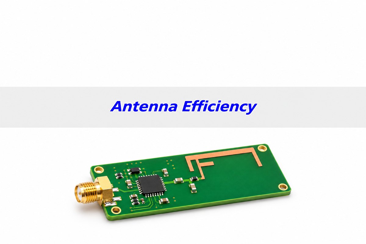
Antenna efficiency definition: where does the power go?
For the single-port convention used here, radiation efficiency is radiated power divided by power accepted at the antenna port. It counts internal dissipative loss, but excludes the power reflected at that port.
Total efficiency also includes mismatch: radiated power divided by incident power at the same reference plane. Always identify that plane. If it is at the antenna feed, an upstream cable’s loss is not automatically included. A report measured at the radio connector may describe a different system boundary.
Picture 100 mW arriving at the port. Some returns toward the source; the remainder is accepted. Of that accepted portion, some is dissipated and the rest radiates. You need all three destinations to understand efficiency. A return-loss measurement addresses only the reflected portion.
Antenna efficiency formula: a worked power budget
Using linear power ratios:
ηrad = Pradiated / Paccepted
ηtotal = (1 − |Γ|²)ηrad
|Γ|² = 10−RL/10, where RL is positive return loss in dB.
Hypothetical example A: incident power is 100 mW, radiation efficiency is 70%, and return loss is 10 dB at one frequency. Reflection is 10%, or 10 mW. Accepted power is 90 mW. Radiated power is 0.70 × 90 = 63 mW; internal dissipation is 27 mW. Total efficiency is 63%, not 70% or 90%.
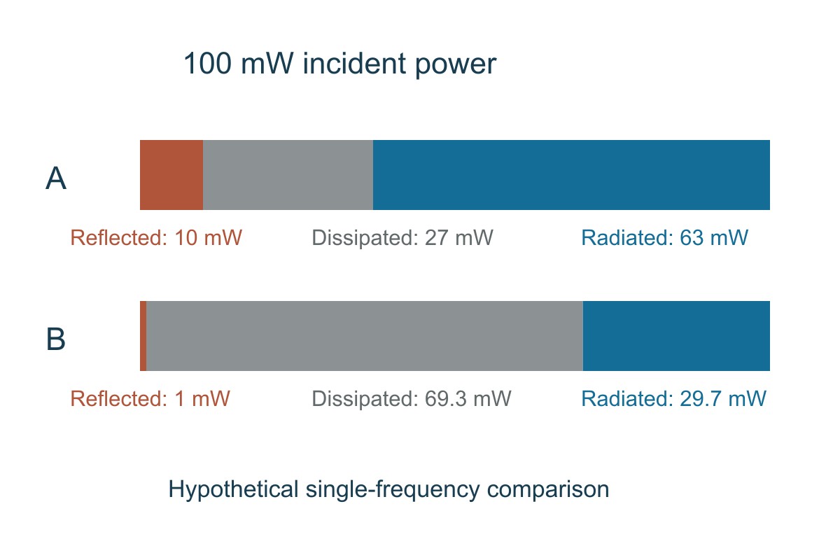
Check conservation before trusting the calculation: reflected + dissipated + radiated = incident. Also check definitions. A supplier’s “efficiency” value may already include mismatch; multiplying it by the matching factor again would count the same loss twice.
Antenna efficiency vs gain: do not confuse loss with direction
Efficiency says how much power is radiated. Directivity says how strongly that radiation is concentrated in a particular direction compared with an isotropic pattern. Gain combines directivity with loss.
| Quantity | Convention in this guide | What it helps decide |
| Radiation efficiency | Radiated / accepted power | How much accepted power is dissipated |
| Total efficiency | Radiated / incident power | Combined mismatch and antenna loss at the defined port |
| Directivity | Directional intensity relative to the average radiation intensity | Where the pattern concentrates energy |
| Gain / realized gain | Directivity × radiation efficiency / directivity × total efficiency | Directional performance excluding / including input mismatch |
These gain conventions follow the distinction used in HFSS documentation. Check another report’s definitions before comparing values: “gain” is not always used with the same mismatch treatment.
For a hypothetical 2.15 dBi directivity in the direction being compared, example A gives gain 2.15 + 10 log10(0.70) = 0.601 dBi. Including mismatch gives realized gain 2.15 + 10 log10(0.63) = 0.143 dBi. The antenna has not generated extra RF power; it distributes the surviving radiated power spatially.
Antenna efficiency in dB: convert a power ratio correctly
Use 10 log10(η) when η is a linear efficiency ratio. Thus 70% is approximately −1.55 dB, and 63% is approximately −2.01 dB. To convert back, efficiency in percent = 100 × 10ηdB/10.
Do not use 20 log10 for this power ratio. Also distinguish positive return loss from the commonly negative S11 magnitude in dB. In example A, return loss is +10 dB and S11 magnitude is −10 dB; the reflected power fraction is 0.10.
Keep the frequency beside every efficiency value. A single number at the center frequency cannot demonstrate performance across a channel band or a multi-band product.
Antenna efficiency measurement: what S11 cannot prove
A calibrated VNA measurement can characterize input reflection at its reference plane. It does not independently separate radiation from dissipative loss. A well-matched lossy load is the simplest reminder: low reflection does not make it an efficient antenna.
Efficiency measurement needs radiated-power or calibrated radiation-pattern information with the input power and reference plane understood. An appropriately configured chamber or other validated antenna-measurement method provides evidence that a simple feed-port trace lacks. One peak-direction measurement is not the same as integrating radiation over the required angular coverage and polarizations.
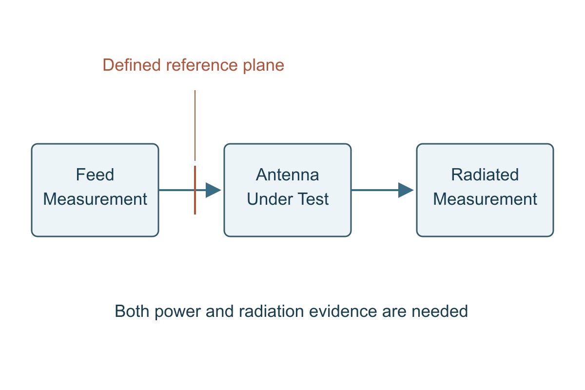
Document feed-cable loss, fixture influence, polarization, angular sampling and measurement uncertainty. Test the intended board, matching components, enclosure and installation state. For active radios, TRP and receiver-sensitivity testing address additional system behavior; a passive antenna efficiency value does not by itself certify the complete transmitter or receiver.
A poor link can also come from non-antenna causes. For example, the phase noise guide explains a separate LO and clock-noise mechanism. Keep that investigation distinct from the antenna’s power accounting instead of changing the antenna to solve an unverified receiver problem.
Return loss vs antenna efficiency: compare the same conditions
Example B has better matching than A: 20 dB rather than 10 dB return loss. But assume its radiation efficiency is only 30%. It accepts 99 mW of the same 100 mW incident power and radiates just 29.7 mW.
| Same-frequency hypothetical comparison | A | B |
| Incident power | 100 mW | 100 mW |
| Return loss | 10 dB | 20 dB |
| Radiation efficiency | 70% | 30% |
| Reflected / internally dissipated power | 10 / 27 mW | 1 / 69.3 mW |
| Radiated power / total efficiency | 63 mW / 63% | 29.7 mW / 29.7% |
| Realized gain if both have 2.15 dBi directivity in the compared direction | 0.143 dBi | −3.122 dBi |
A radiates approximately 3.27 dB more power in this example despite its poorer return loss. That does not establish a fixed communication distance: propagation, pattern, orientation, polarization and receiver performance remain relevant. Choose B only if the complete application comparison supports it—not because its S11 dip is deeper.
Antenna efficiency in applications: what should you verify?
Compact IoT and wearable boards
The board ground, antenna keepout and nearby battery or enclosure can form part of the operating antenna environment. Preserve the required pattern and radiation while fitting the product, rather than optimizing a bare-board S11 curve alone.
Start from the antenna vendor’s actual layout constraints; there is no universal keepout dimension for all antennas. Compare the intended assembly states, including realistic body proximity where relevant. Verify total efficiency across the operating band and test product-level link performance in required orientations. The antenna detuning guide covers the separate matching-shift investigation.
External antennas with cables and connectors
An efficient antenna at its own feed can still receive less power through a lossy cable or connector chain. Put the reference plane in the specification. If the system requirement begins at the radio connector, include or separately account for the intervening losses.
Measure the feed path over the required frequencies, then combine it with antenna evidence using consistent reference planes. Verify the installed connector, cable routing and polarization. Do not add a cable-loss correction to a report that already includes that cable.
Directional gateways and fixed links
A more directional antenna can improve realized gain toward a known endpoint while reducing coverage elsewhere. An efficiency percentage alone cannot tell whether that is beneficial. Preserve sufficient coverage in required directions; avoid solving a fixed-link problem with an unsupported claim of better all-around range.
Compare realized patterns, alignment and polarization at the intended frequencies. Verify the actual link margin or required system metric under the deployment conditions. For multi-antenna equipment, isolation and pattern relationships also need their own checks; high single-antenna efficiency is not a complete MIMO assessment.
Improving antenna efficiency: isolate the loss before changing the design
First identify whether the limitation is mismatch, internal dissipation, the feed path or directional coverage. Those require different changes. A matching network can transform impedance; it cannot automatically recover power dissipated in a lossy structure, and its own components can add loss.
Compare one controlled change at a time: matching values, material or conductor configuration, approved keepout, enclosure state or cable path. Keep the reference plane and measurement method fixed. If S11 improves but radiated efficiency falls, do not approve the change as an improvement based only on the feed-port result.
PCB material and geometry can matter, but “use a lower-loss laminate” is not a universal fix. Determine whether the relevant loss actually occurs in that material and whether the geometry and mechanical constraints remain valid. Compare the expected benefit with manufacturing and cost implications, then validate the assembled result.
Antenna efficiency report checklist: can you accept the result?
Use this worksheet when comparing samples or reviewing a supplier report. Define the required values from the product’s link budget and test plan; no single efficiency threshold applies to every antenna.
| Check | Required evidence | If missing |
| Quantity and reference plane | Radiation or total efficiency, included feed path, and gain convention | Hold the numerical comparison until definitions match |
| Frequency coverage | Results over the required operating band | Do not accept a center-frequency point as full-band evidence |
| Assembly state | PCB revision, enclosure, battery, cables, matching values and mounting | Resolve whether the result represents the delivered configuration |
| Method and uncertainty | Calibrated radiated measurement, power accounting and uncertainty information | Ask the lab which conclusions its method supports |
| System requirement | Agreed efficiency/pattern targets and applicable active-radio tests | Do not infer a product pass from an antenna percentage alone |
Worked review: a report says “70% efficiency” but gives no mismatch treatment or reference plane. Mark the comparison hold. Ask whether that is radiation or total efficiency and whether the cable is included. If it is radiation efficiency at the antenna feed and the measured return loss is 10 dB there, total efficiency is 63% under the single-port convention used above. Then compare that result—not the unqualified 70%—with the relevant requirement.
Antenna Efficiency FAQs
Does −20 dB S11 mean 99% antenna efficiency?
No. It corresponds to about 1% reflected power, so approximately 99% is accepted at that port. Some accepted power can be dissipated rather than radiated.
What is the difference between radiation and total efficiency?
Here, radiation efficiency uses accepted power; total efficiency uses incident power and includes mismatch. Both must use a defined reference plane.
How do I convert 70% efficiency into dB?
Use 10 log10(0.70), approximately −1.55 dB. It is a power ratio, not an amplitude ratio.
Can a VNA alone measure radiation efficiency from S11?
Not from S11 alone. You also need suitable radiated-power or calibrated pattern evidence to distinguish radiation from internal loss.
Can an antenna have high gain but modest efficiency?
Yes, sufficient directivity can produce high gain in a particular direction despite losses. That does not mean it provides better coverage in all directions.
Why can a better match produce worse radiated performance?
A changed structure or matching network may accept power while dissipating more of it. Compare radiation or total efficiency as well as reflection under the same conditions.
What efficiency is acceptable for a PCB antenna?
It depends on frequency, bandwidth, size, environment, coverage and system requirements. Set a justified target and measure the intended product configuration; there is no universal percentage.
Does a bare-board test confirm antenna efficiency?
No. Bare-board checks can verify manufacturing requirements, but assembled antenna and product performance require the relevant RF and radiated measurements.
Technical References
- Rohde & Schwarz: Demystifying OTA Testing — radiation and total efficiency.
- Ansys HFSS: gain definition and realized gain definition — accepted versus incident power conventions.
- Texas Instruments AN058 — antenna selection and radiated measurements.
- Keysight: antenna measurement — pattern and OTA measurement scope.
- Silicon Labs AN1088 and AN686 — antenna ground and layout context.
Custom RF PCB Manufacturing with Prototype and Assembly Support
Need custom antenna or RF circuit boards for your next build? EBest Circuit supports RF PCB fabrication, prototype production and PCB assembly. Reviewing material, stackup, controlled geometry and assembly requirements together helps turn an approved RF design into a clear manufacturing package.
Send your fabrication files, material requirements, stackup, impedance targets and quantity to sales@bestpcbs.com for a quotation. Include the BOM and placement data for PCBA, and identify any required antenna or radio functional tests. Let the manufacturing scope and test scope be evaluated explicitly—without assuming that a bare-board inspection guarantees radiated performance.