PCB manufacturing PCB manufacturing
Home > Blog

FAKRA PCB Connector

FAKRA PCB Connector Guide for Automotive PCBA Integration
Thursday, September 17th, 2026

A FAKRA PCB connector must match more than a housing color. The mechanical code, mating gender, orientation, PCB termination, footprint, frequency rating, and mating cable all need to agree before the board is released.

EBest Circuit (Best Technology) supports controlled-impedance PCB fabrication, component sourcing, SMT and through-hole assembly, first-article inspection, and customer-defined testing. Send the connector drawing, Gerber files, stackup, BOM, assembly drawing, quantities, and test limits to sales@bestpcbs.com for a manufacturing review.
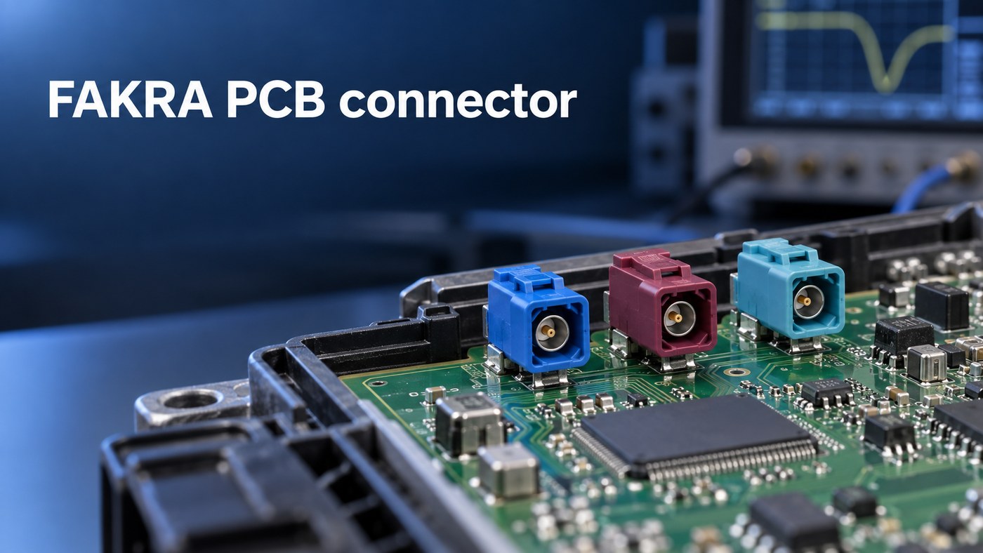
FAKRA PCB connector
PCB-mounted FAKRA connectors for automotive PCBA integration.

What Is a FAKRA PCB Connector?

A FAKRA PCB connector is a keyed, locking, 50-ohm automotive coaxial interface. It connects a cable harness to a PCB used in equipment such as a telematics control unit, head unit, antenna module, or camera ECU.

The metal interface is based on SMB, while the plastic housing adds mechanical coding, color identification, and a latch. Depending on the exact series, the product specification may cite ISO 20860-1, SAE/USCAR-17, SAE/USCAR-18, or OEM requirements.

“FAKRA” is only the product family. A production BOM still needs the full manufacturer part number, mating part, code, orientation, PCB termination, and current product drawing.

FAKRA Connector Types and Codes for PCB-Mounted Applications

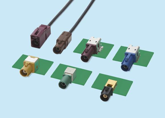
PCB-mounted FAKRA connectors are available in straight or vertical (180-degree) and right-angle (90-degree) versions. Product families may also offer single, dual, or multiport housings; sealed or unsealed construction; and through-hole, pin-in-paste, or SMD termination. Some device-side designs use a separate press-in contact or housing arrangement, but its attachment to the chassis and PCB must be read from the exact product drawing.

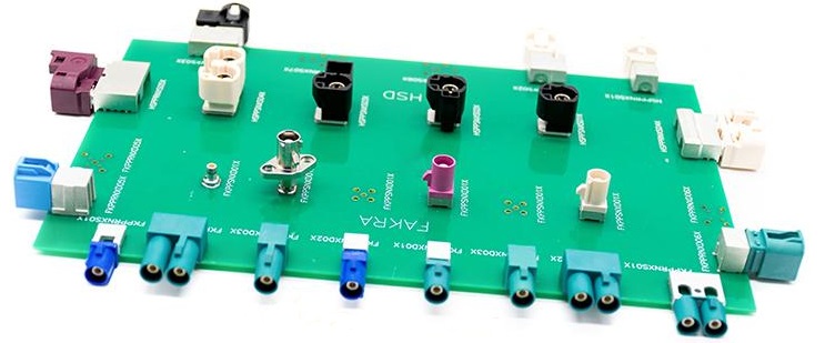
FAKRA has 14 coding options—not 14 electrical models. A, B, C, D, E, F, G, H, I, K, L, M, and N are 13 different mechanical keys. Z is the neutral key.

The standard colors and common application assignments are:

CodeColorCommon assignment*
AJet blackRadio without phantom power
BCreamRadio with phantom power
CSignal blueGPS, telematics, navigation
DClaret violetGSM or cellular
ELeaf greenTV1, UHF TV, terrestrial SDARS
FNut brownTV2, VHF TV, terrestrial SDARS
GBlue greyRemote keyless entry or terrestrial SDARS
HHeather violetGPS, telematics, navigation
IBeigeParking heater or Bluetooth
KCurryDiversity radio or satellite SDARS
LCarmine redOEM- or program-defined
MPastel orangeKeyless entry or tire-pressure monitoring
NPastel greenOEM- or program-defined
ZWater blueNeutral key

*Application assignments vary between European, USCAR, and individual OEM conventions. The vehicle drawing and approved BOM remain controlling.

A–N normally mate only with the matching key and compatible gender. Z can mate with A–N only when the connector family, contact gender, and mating geometry are otherwise compatible. The assembly record should therefore identify the full part number and code—not merely “blue FAKRA.”

Top 5 FAKRA Connector Manufacturers

These five established manufacturers offer different PCB-mount portfolios. Start with the brand approved for the mating cable or vehicle platform, then compare the exact part and availability.

ManufacturerBest fit
RosenbergerBroad straight and right-angle PCB range with pin-in-paste, wave-solder, and SMD versions
TE ConnectivitySealed and unsealed coded systems for platforms using several FAKRA ports
Amphenol RFVertical, right-angle, through-hole, surface-mount, and end-launch choices
MolexFAKRA and FAKRA II board/harness systems, including right-angle through-hole and pin-in-paste products
RaydiallReflow- and wave-soldered PCB connectors, plus a separate press-in contact route for compatible designs

Brand alone does not establish interchangeability. Compare the code, RF gender, orientation, footprint, shield-pin pattern, termination, sealing, frequency rating, packaging, and approved mating part before accepting an alternate.

FAKRA Connector PCB Mount Selection: Straight, Right-Angle, or Through-Hole

Make two choices separately. Straight versus right-angle defines the cable-mating direction; through-hole, pin-in-paste, or SMD defines how the connector terminates to the PCB. A separate press-in feature, where offered, may attach part of the connector to the module chassis rather than replace the PCB solder joint. A connector can be both right-angle and through-hole.

ChoiceTypical application
Straight / vertical (180°)Top-entry modules, antenna hubs, or multiport units with cable access above the PCB
Right-angle (90°)Low-profile ECUs, head units, camera modules, or side-entry enclosures
Through-holeDesigns that need strong shield-leg and mounting-post retention against cable loads
Pin-in-pasteMixed-SMT production that needs through-hole retention but uses the reflow line
SMDCompact automated builds using a connector designed specifically for surface mounting
Press-in device-side designSelected modules in which the connector contact or housing is pressed into a sheet-metal or die-cast chassis; the PCB terminal may still require soldering, so the exact drawing controls

Check the cable, enclosure, board edge, and mating direction in the assembled 3D model. A connector that fits the PCB view can still fail because the cable cannot bend, the latch cannot be reached, or insertion force flexes the board edge.
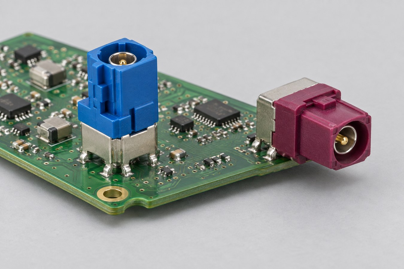
FAKRA PCB connector
Vertical and right-angle FAKRA PCB connector orientations.

What Is the Frequency Range of a FAKRA Connector?

Standard 50-ohm FAKRA families are commonly rated from DC to 6 GHz. Some earlier or application-specific parts stop at 3 or 4 GHz, so the exact part-number drawing is the final authority.

Selected broadcast cable assemblies may operate above 6 GHz, but that rating does not automatically apply to a PCB header. Mini-FAKRA and HFM are also different interfaces, not higher-frequency drop-in replacements for standard FAKRA.

A 6 GHz connector does not guarantee a 6 GHz channel. The cable, mated pair, PCB launch, trace, adapters, and test fixture all affect insertion loss and return loss.

FAKRA PCB Layout for 50-Ohm Signal Integrity

Use the land pattern for the exact connector and calculate the trace from the production stackup. Similar-looking FAKRA parts can have different center-pin positions, shield posts, locating features, and ground clearances.

The launch should control four points:

  • Signal transition: Keep the center-pin pad and stub as short as the approved footprint allows.
  • Return path: Connect the shield structure to an uninterrupted reference plane with a balanced ground-via arrangement.
  • 50-ohm line: Calculate the trace from the actual dielectric thickness, Dk, copper, solder mask, and line type.
  • Mechanical support: Align the connector datum with the enclosure and support the board edge against repeated mating force.

An impedance coupon verifies a representative transmission-line geometry from the fabricated stackup; it does not by itself verify the connector launch on every board. A connectorized first article measured by TDR or VNA is needed to verify the launch. Our RF PCB manufacturing guide covers the related stackup and impedance controls.

FAKRA Connector PCB Assembly and Soldering Control

The assembly route must follow the exact connector termination.

TerminationMain production control
Pin-in-pasteStencil aperture, paste volume, pin protrusion, seating, reflow limit, and solder fill
Conventional through-holeConnector support, preheat, dwell, barrel fill, solder bridging, and housing temperature
SMDPackaging, placement method, coplanarity, paste deposit, and body support
Press-in contact or housingExact receiving-chassis dimensions, insertion tooling, force window, connector seating, and the separate PCB-terminal process shown on the released drawing

The first article should confirm code direction, seating height, clean mating surfaces, solder quality, and unobstructed cable latching. Shield pins provide both mechanical retention and the RF return path, so incomplete soldering can affect strength and signal performance.

Accepted photos, dimensions, solder criteria, and process settings should then move into the work instruction. Mixed builds that reflow electronics and selectively solder the connector also need a defined sequence and suitable fixtures. See our mixed-technology PCB assembly service for the related assembly approach.
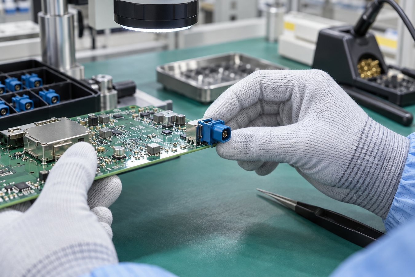
FAKRA PCB connector
Inspection of a PCB-mounted FAKRA connector during PCBA assembly.

Inspection and RF Testing for a FAKRA Connector PCB

Each inspection method answers a different question.

EvidenceWhat it proves
Incoming inspection and FAICorrect manufacturer, part number, code, lot, and orientation
Visual inspection, AOI, or X-raySeating, visible joints, hidden solder, or barrel fill as applicable
Bare-board electrical test and impedance coupon/TDRCorrect copper network and controlled PCB transmission line
Calibrated VNA measurementS11/return loss and S21/insertion loss of the defined connectorized path

AOI cannot measure impedance, and continuity testing cannot reveal a launch that is electrically connected but badly mismatched. Pull or retention testing should be limited to qualification or designated first-article samples when required by the released test plan.

An RF report should identify the sample, fixture, calibration method, reference plane, frequency sweep, and pass/fail limits. Without those details, two VNA plots are not directly comparable.
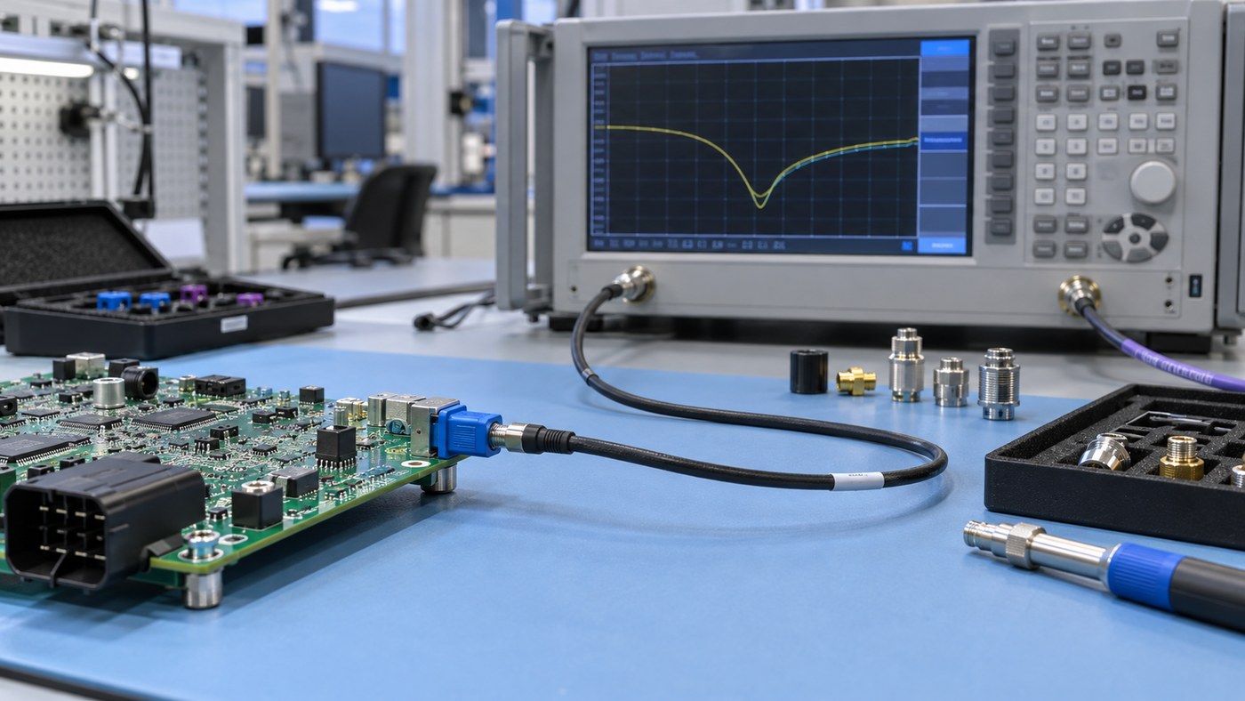
FAKRA PCB connector
Connectorized RF verification of a FAKRA-equipped PCB using a VNA setup.

How to Source a FAKRA PCB Connector for PCBA Production

Specify the connector at full-part-number level. The BOM should identify the manufacturer, code/color, RF gender, orientation, PCB termination, packaging, and approved mating part. It should also state whether alternates are prohibited or require written approval.

Do not approve a substitute because it has the same color or distributor description. Recheck the mechanical key, mating interface, footprint, shield-pin pattern, height, sealing, frequency rating, soldering process, packaging, and qualification status.

Use an authorized supply channel and retain the connector lot/date code, required compliance documents, and change notifications. EBest Circuit can review availability and manufacturing compatibility, while the customer approves changes affecting the RF channel or vehicle interface.

How EBest Circuit Supports FAKRA Connector PCB Manufacturing

EBest Circuit turns an approved FAKRA interface into a controlled PCB and PCBA manufacturing package.

  • Before production: We cross-check the connector drawing, footprint, mating cable, enclosure direction, stackup, soldering route, and test requirement.
  • For the first article: We coordinate controlled-impedance PCB fabrication, approved sourcing, the documented assembly process, seating and solder inspection, bare-board testing, and impedance records. Fixture-based RF testing may be added only after EBest Circuit confirms the required equipment and test capability, and the customer approves the fixture, calibration method, reference planes, sweep, and acceptance limits.
  • For repeat orders: The connector lot, PCB revision, assembly records, inspection results, and approved changes remain linked to the production batch.

EBest Circuit’s owned PCB and PCBA facilities, ISO 9001 and IATF 16949 quality systems, and prototype-to-repeat-production support help reduce handoffs. Pin-in-paste, conventional through-hole, and SMD processes can be planned from the released drawing. Press-in connector or housing designs require a separate review of the chassis interface, insertion tooling, force window, PCB-terminal method, and factory capability.

Send the connector and PCB package to sales@bestpcbs.com for a project-specific review.

FAQs About FAKRA PCB Connectors

What does FAKRA mean?

FAKRA comes from the German term Fachkreis Automobil and identifies a standardized family of keyed automotive coaxial connectors.

Is FAKRA Z universal?

Z is the neutral mechanical key, but gender, interface family, footprint, termination, frequency rating, and sealing must still match.

Does each FAKRA color have one fixed application?

No. Colors identify mechanical codes, while application assignments can differ between European, USCAR, and individual OEM conventions.

Are FAKRA connectors waterproof?

Only specified sealed versions provide environmental sealing, usually when correctly mated with the approved counterpart.

Do FAKRA connectors require special crimping tools?

Crimp-terminated cable contacts require approved stripping, crimping, and inspection tooling. PCB-mounted versions follow the through-hole soldering, pin-in-paste reflow, or SMD process specified in the product drawing. A separate press-in contact or housing feature, where used, must follow its own chassis and PCB-terminal instructions.

Can straight and right-angle FAKRA connectors share one PCB footprint?

Do not assume so. Center-pin location, shield posts, locating features, and housing datum can change even within one manufacturer’s range.

If your FAKRA PCB connector project is ready for prototype or repeat production, send the exact connector drawing, PCB files, mating information, and test limits to sales@bestpcbs.com. EBest Circuit can review the component, RF PCB, assembly, and acceptance requirements before production release.

You may also like

Rigorous Quality FAKRA PCB for Automotive Industry
Thursday, December 4th, 2025

A FAKRA PCB​ is a specialized printed circuit board designed to integrate FAKRA coaxial connectors, serving as the critical RF signal interface in modern vehicles for applications like GPS, infotainment, and ADAS. Are you facing recurring challenges with signal integrity, reliability, or sourcing for your automotive RF modules? This article provides a comprehensive guide to designing, specifying, and manufacturing reliable FAKRA PCBs that meet the stringent quality and performance demands of the automotive industry.

What are the typical pain points engineers face when working with FAKRA PCBs?

  • Impedance Mismatch:​ Inaccurate PCB trace design or material inconsistency leads to a deviation from the required 50Ω impedance, causing signal reflections errors.
  • Mechanical Failure in Harsh Environments:​ Vibration, temperature cycling, and connector mating cycles can cause the FAKRA PCB mount​ to fail, leading to disconnections in critical systems.
  • Unstable High-Frequency Performance:​ Understanding and designing for FAKRA connectors PCB frequency​ limits (up to 6 GHz) is challenging, often resulting in unexpected insertion loss and VSWR.
  • Supply Chain Complexity:​ Sourcing correct components, like specific HCC FAKRA PCB part numbers, and dealing with long lead times or counterfeit parts can derail production schedules.
  • Miniaturization Difficulties:​ Integrating miniature FAKRA connectors PCB​ into compact telematics and ADAS modules requires advanced design and manufacturing capabilities to avoid crosstalk and ensure robustness.

At BEST Technology, we address these challenges with rigorous process controls and automotive-grade expertise, ensuring your FAKRA PCB performs flawlessly.

  • Controlled Impedance Fabrication:​ We utilize high-frequency laminates and precise modeling to guarantee your FAKRA PCB connector​ footprint translates to a consistent 50Ω transmission line, minimizing signal degradation.
  • Automotive-Grade Mechanical Design:​ Our DFM analysis includes checks for solder joint integrity, reinforced PTH barrels, and optimal FAKRA PCB mount​ design to withstand vibration and thermal stress, ensuring long-term reliability.
  • High-Frequency Optimization:​ Our expertise with FAKRA connectors PCB frequency​ requirements ensures stable performance up to 6 GHz through careful material selection and layout guidance.
  • Verified Component Supply Chain:​ We have partnerships with reputable FAKRA connector manufacturers, guaranteeing access to authentic components like specific HCC FAKRA PCB part numbers, simplifying your logistics.
  • Advanced Miniaturization Support:​ We provide design rules and precision manufacturing for boards using miniature FAKRA connectors PCB, ensuring reliable performance in the smallest form factors.

BEST Technology is a specialist in high-reliability PCB and assembly manufacturing, with a strong focus on automotive electronics. With IATF 16949 certified production facilities in China and Vietnam, we offer a true one-stop service from FAKRA PCB​ fabrication to full box-build assembly. Contact us at sales@bestpcbs.com​ for a consultation.

FAKRA PCB

What Is a FAKRA PCB?

A FAKRA PCB​ is a circuit board engineered to host FAKRA (Fachkreis Automobil) connectors, which are standardized coaxial interfaces used primarily in automobiles for transmitting radio frequency signals.

  • Core Purpose:​ The primary role of a FAKRA PCB is to provide a reliable, impedance-controlled pathway for RF signals from a coaxial cable to the board’s integrated circuits, supporting systems like GPS, satellite radio, and cellular connectivity.
  • Key Feature – Color Coding:​ A defining feature is the use of color-coded connector housings (e.g., blue for GPS, yellow for USB) on the FAKRA PCB connector, which prevents mis-mating during assembly in the vehicle harness.

FAKRA Connector Color and Coding Guide

ColorCode LetterPrimary ApplicationTypical Frequency Range
BlueAGPS (Global Positioning System)1.575 GHz
Light GreenBReserved / User-Defined
GrayCSDARS (Satellite Digital Audio Radio Service)2.32 – 2.345 GHz
PinkDCellular Phone (2G/3G/4G Telematics)800 MHz – 2.7 GHz
BlackEReserved / User-Defined
GreenFCarPlay / Android Auto (LVDS Differential Signals)
RedGGPS (Modern de facto standard)1.575 GHz
BrownHSDARS (Satellite Radio)2.32 – 2.345 GHz
WhiteJBluetooth / Wi-Fi2.4 GHz / 5 GHz
OrangeKTire Pressure Monitoring System (TPMS)433 MHz / 315 MHz
YellowLDigital Audio Broadcasting (DAB/DAB+)174 – 240 MHz
Light BlueMVehicle TV Tuner470 – 862 MHz
Violet / PurpleN, P, R, SV2X / DSRC (Vehicle-to-Everything)5.85 – 5.925 GHz
Black (4-pin)U, V, W, X, ZAutomotive Radar (ADAS)24 GHz / 76-81 GHz

In summary, a FAKRA PCB is a fundamental component in modern automotive electronics, ensuring that various RF systems can be connected correctly and perform reliably over the vehicle’s lifetime.

FAKRA PCB

How a FAKRA PCB Connector Enables Stable RF Transmission in Automotive Electronics?

The FAKRA PCB connector​ is the critical interface that ensures stable RF transmission by maintaining signal integrity from the cable to the PCB. Its design is tailored for the harsh automotive environment.

  • Standardized Impedance:​ The connector is engineered to maintain a 50-ohm impedance through its interface, providing a smooth transition to the similarly controlled impedance trace on the PCB. This minimizes reflections at the connection point.
  • Superior Shielding:​ The metal shell of the connector, when soldered to a continuous ground plane on the PCB, creates an excellent shield against electromagnetic interference (EMI), which is abundant in a vehicle.
  • Robust Keying Mechanism:​ The unique plastic keying and color coding of a FAKRA connector​ prevent incorrect mating, ensuring that the right signal source is always connected to the right receiver, which is vital for system functionality.

The FAKRA PCB connector​ is more than just a port; it precision-engineered component that guarantees stable RF signal transmission by combining electrical precision, mechanical robustness, and error-proofing.

FAKRA PCB

What are FAKRA Connectors PCB Frequency Limits and Why They Matter in High-Speed Designs?

Understanding the FAKRA connectors PCB frequency​ limits is crucial for ensuring system performance, as these limits define the maximum data rate the connection can support without significant signal degradation.

  • Standard Limit:​ Standard FAKRA connectors are typically rated for frequencies up to 6 GHz. This covers most automotive applications like GPS (1.5 GHz), 4G/LTE, and Wi-Fi.
  • Importance for High-Speed Designs:​ As automotive systems evolve towards 5G and higher-speed data (e.g., for camera modules), operating frequencies increase. If the FAKRA connectors PCB frequency​ limit is exceeded, insertion loss rises and VSWR increases, leading to a weak or corrupted signal. This makes the 6 GHz limit a key consideration when selecting components for future-proof designs.

Therefore, the FAKRA connectors PCB frequency​ specification is not just a number; it is a boundary that dictates the suitability of the connector for current and emerging high-bandwidth applications in the vehicle.

Understanding FAKRA PCB Mount Options for Robust RF and GPS/4G/Wi-Fi Modules

The FAKRA PCB mount​ option chosen directly impacts the mechanical stability and long-term reliability of the RF connection in modules that are subject to constant vibration.

  • Through-Hole Mounting (TH):​ This method involves leads inserted into plated-through holes in the PCB and soldered. It offers the highest mechanical strength and is preferred for applications where the connector might undergo significant mating force or extreme vibration.
  • Surface Mount Technology (SMT):​ SMT FAKRA PCB mount​ connectors are soldered to pads on the PCB surface. This allows for faster, more automated assembly and is ideal for high-volume production. The mechanical strength is generally lower than THT but sufficient for many applications with proper design.

Selecting the right RA PCB mount​ style—through-hole for maximum robustness or surface-mount for assembly efficiency—is a critical decision based on the specific mechanical demands and production volume of the automotive module.

Overview of HCC FAKRA PCB Part Numbers and How They Differ Across Connector Families

HCC FAKRA PCB part numbers​ refer to the specific coding system used by a major connector manufacturer (Hirose) to identify different FAKRA connector variants. Understanding these part numbers is key to sourcing the correct component.

  • Decoding the Number:​ A typical HCC FAKRA PCB part number provides encoded information about the connector’s series, color, keying code, mounting style (right-angle, vertical), and termination type.
  • Differences Across Families:​ Different series within the HCC catalog may offer variations in size (e.g., miniaturized), performance (e.g., higher frequency), or locking mechanism. For example, a part number for a mini FAKRA PCB​ connector would belong to a different series than a standard-sized one.

Therefore, paying close attention to HCC FAKRA PCB part numbers​ is essential for engineers to ensure the selected connector matches the electrical, mechanical, and spatial requirements of their specific PCB design.

Miniature FAKRA Connectors PCB Design Rules for Compact Automotive and Telematics Devices

Designing with ​ FAKRA connectors PCB​ components requires adherence to specific rules to maintain signal integrity and mechanical stability in increasingly compact devices.

  • Prioritize Grounding:​ Even more so than with standard connectors, a solid ground connection is vital. Use an extensive ground plane directly under and around the connector footprint, with multiple vias adjacent to the ground pads to minimize inductance.
  • Maintain Impedance Continuity:​ The reduced size makes impedance control more challenging. Work closely with your PCB manufacturer to ensure the trace width and spacing as it exits the miniature connector maintains 50Ω.
  • Manage Crosstalk:​ Place other components and high-speed traces a sufficient distance away from the miniature FAKRA connectors PCB​ to prevent unwanted coupling and crosstalk.

Following these design rules for mini FAKRA PCB​ integration allows engineers to leverage space savings without compromising the RF performance that is critical for advanced telematics and ADAS modules.

How Do You Integrate a FAKRA Stecker PCB into Automotive Platforms and ADAS Harness Systems?

Integrating a FAKRA Stecker PCB​ (German for “FAK PCB”) involves both electrical and mechanical considerations to ensure a reliable connection within the vehicle’s larger wiring harness system, especially for ADAS.

  • Harness Interface Planning:​ The FAKRA Stecker PCB​ on a module (e.g., a radar or camera) must be positioned to align correctly with the vehicle’s pre-designed wire harness. This requires close collaboration with the harness supplier early in the design phase.
  • In-Line Connector Choice:​ The FAKRA Stecker PCB​ (plug) mates with an in-line FAKRA connector (socket) on the harness. Selecting the correct keying and color code for this mating pair is essential to ensure each sensor and antenna is connected in the complex ADAS network.

Successful integration of the FAKRA Stecker PCB​ is a systems-level task that ensures the electronic module becomes a seamless and reliable part of the vehicle’s broader communication infrastructure.

Comparing PCB to PCB Connector Types in RF Applications vs. Standard FAKRA Types

When connecting two PCBs carrying RF signals, engineers must choose between standard PCB to PCB connector types​ and dedicated FAKRA types, each with distinct advantages.

  • Standard PCB-to-PCB Connectors:​ These include mezzanine, board-to-board, and stacking connectors. They are versatile for general power and data but are often not optimized for RF potentially introducing significant impedance discontinuities and loss at high frequencies.
  • FAKRA Types:FAKRA connectors​ are specifically engineered as RF coaxial interfaces. They provide superior shielding and a controlled 50-ohm impedance path, making them the clear choice for high-frequency signals like GPS or cellular. However, they are typically used for cable-to-board connections, not direct PCB-to-PCB links.

The choice boils down to application: use standard PCB to PCB connector types​ for general purposes, but always specify FAKRA types​ when the primary function is to carry a clean RF signal between a cable and the board.

Why Automotive Teams Choose EBest Circuit (Best Technology) for FAKRA PCB and Full PCBA Manufacturing Support?

Automotive engineering teams partner with BEST Technology because we deliver the rigorous quality and specialized support mission-critical FAKRA PCB​ applications. Our services are built to meet the high standards of the automotive industry.

  • Automotive-Grade Expertise:​ We specialize in manufacturing FAKRA PCB​ and high-frequency boards for automotive electronics, including advanced driver-assistance systems (ADAS) modules, camera boards, and antenna modules.
  • Global Manufacturing Footprint:​ Our IATF 16949 certified PCB and SMT factories in China and Vietnam offer scalable production from quick-turn prototypes to high-volume mass production, ensuring supply chain resilience.
  • Comprehensive Engineering Support:​ We provide free DFM analysis, impedance control advice, and stack-up recommendations to optimize your design for performance and manufacturability.
  • Full-Turnkey PCBA Service:​ We manage the entire process from FAKRA PCB​ fabrication and component sourcing (including authentic FAKRA connector​ procurement) to precise SMT assembly, rigorous testing, and final shipment.
  • Rigorous Quality Assurance:​ Our compliance with IATF 16949, ISO 13485, ISO 9001, and UL standards, combined with MES traceability, guarantees that every board meets the zero-defect expectations of the automotive sector.
FAKRA PCB

In summary, FAKRA PCB​ technology is a cornerstone of in-vehicle connectivity, demanding precision from design through assembly. This guide has detailed the essential aspects of specifying, designing, and manufacturing robust PCBs with FAKRA connectors to meet the rigorous quality demands of the automotive industry. By choosing BEST Technology as your manufacturing partner, you gain access to specialized automotive-grade expertise, stringent process controls, and a seamless one-stop service that ensures your designs perform reliably in the field.

Ready to get a quote for your automotive-grade FAKRA PCB?​ Pls email your Gerber files, BOM, and connector specifications to sales@bestpcbs.com​ for a fast and comprehensive engineering review and quote.

You may also like