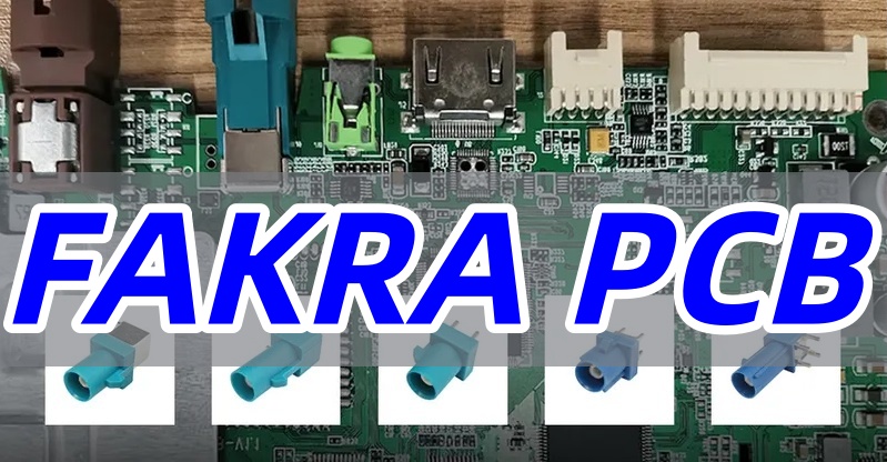
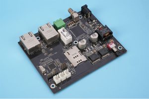
A FAKRA PCB connector must match more than a housing color. The mechanical code, mating gender, orientation, PCB termination, footprint, frequency rating, and mating cable all need to agree before the board is released.
EBest Circuit (Best Technology) supports controlled-impedance PCB fabrication, component sourcing, SMT and through-hole assembly, first-article inspection, and customer-defined testing. Send the connector drawing, Gerber files, stackup, BOM, assembly drawing, quantities, and test limits to sales@bestpcbs.com for a manufacturing review.
What Is a FAKRA PCB Connector?
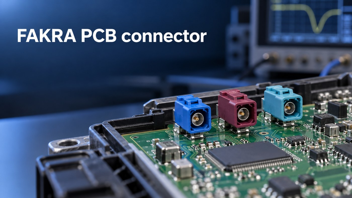
A FAKRA PCB connector is a keyed, locking, 50-ohm automotive coaxial interface. It connects a cable harness to a PCB used in equipment such as a telematics control unit, head unit, antenna module, or camera ECU.
The metal interface is based on SMB, while the plastic housing adds mechanical coding, color identification, and a latch. Depending on the exact series, the product specification may cite ISO 20860-1, SAE/USCAR-17, SAE/USCAR-18, or OEM requirements.
“FAKRA” is only the product family. A production BOM still needs the full manufacturer part number, mating part, code, orientation, PCB termination, and current product drawing.
FAKRA Connector Types and Codes for PCB-Mounted Applications
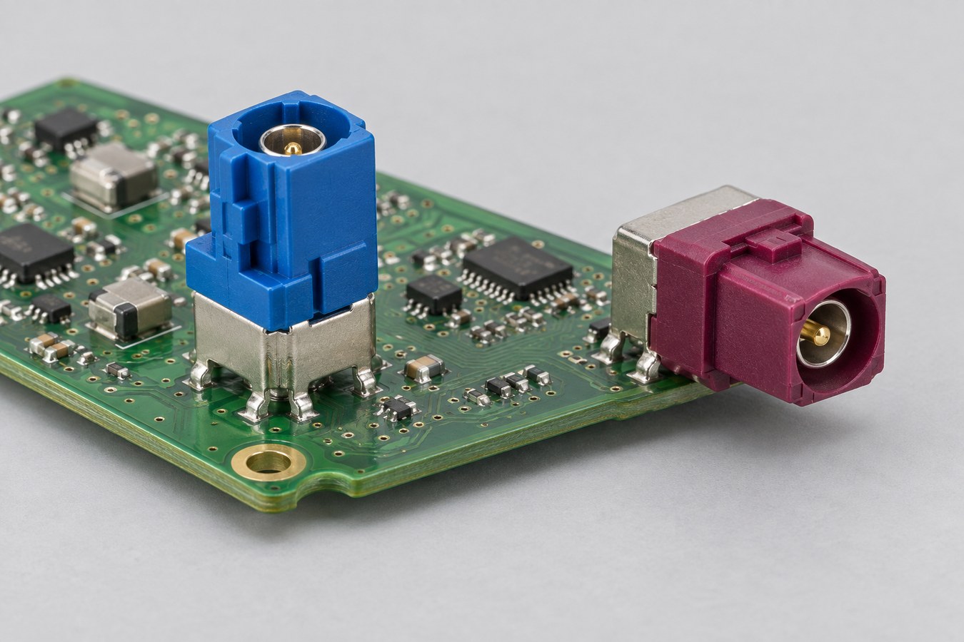
PCB-mounted FAKRA connectors are available in straight or vertical (180-degree) and right-angle (90-degree) versions. Product families may also offer single, dual, or multiport housings; sealed or unsealed construction; and through-hole, pin-in-paste, or SMD termination. Some device-side designs use a separate press-in contact or housing arrangement, but its attachment to the chassis and PCB must be read from the exact product drawing.
FAKRA has 14 coding options—not 14 electrical models. A, B, C, D, E, F, G, H, I, K, L, M, and N are 13 different mechanical keys. Z is the neutral key.
The standard colors and common application assignments are:
| Code | Color | Common assignment* |
|---|---|---|
| A | Jet black | Radio without phantom power |
| B | Cream | Radio with phantom power |
| C | Signal blue | GPS, telematics, navigation |
| D | Claret violet | GSM or cellular |
| E | Leaf green | TV1, UHF TV, terrestrial SDARS |
| F | Nut brown | TV2, VHF TV, terrestrial SDARS |
| G | Blue grey | Remote keyless entry or terrestrial SDARS |
| H | Heather violet | GPS, telematics, navigation |
| I | Beige | Parking heater or Bluetooth |
| K | Curry | Diversity radio or satellite SDARS |
| L | Carmine red | OEM- or program-defined |
| M | Pastel orange | Keyless entry or tire-pressure monitoring |
| N | Pastel green | OEM- or program-defined |
| Z | Water blue | Neutral key |
*Application assignments vary between European, USCAR, and individual OEM conventions. The vehicle drawing and approved BOM remain controlling.
A–N normally mate only with the matching key and compatible gender. Z can mate with A–N only when the connector family, contact gender, and mating geometry are otherwise compatible. The assembly record should therefore identify the full part number and code—not merely “blue FAKRA.”
Top 5 FAKRA Connector Manufacturers
These five established manufacturers offer different PCB-mount portfolios. Start with the brand approved for the mating cable or vehicle platform, then compare the exact part and availability.
| Manufacturer | Best fit |
|---|---|
| Rosenberger | Broad straight and right-angle PCB range with pin-in-paste, wave-solder, and SMD versions |
| TE Connectivity | Sealed and unsealed coded systems for platforms using several FAKRA ports |
| Amphenol RF | Vertical, right-angle, through-hole, surface-mount, and end-launch choices |
| Molex | FAKRA and FAKRA II board/harness systems, including right-angle through-hole and pin-in-paste products |
| Raydiall | Reflow- and wave-soldered PCB connectors, plus a separate press-in contact route for compatible designs |
Brand alone does not establish interchangeability. Compare the code, RF gender, orientation, footprint, shield-pin pattern, termination, sealing, frequency rating, packaging, and approved mating part before accepting an alternate.
FAKRA Connector PCB Mount Selection: Straight, Right-Angle, or Through-Hole
Make two choices separately. Straight versus right-angle defines the cable-mating direction; through-hole, pin-in-paste, or SMD defines how the connector terminates to the PCB. A separate press-in feature, where offered, may attach part of the connector to the module chassis rather than replace the PCB solder joint. A connector can be both right-angle and through-hole.
| Choice | Typical application |
|---|---|
| Straight / vertical (180°) | Top-entry modules, antenna hubs, or multiport units with cable access above the PCB |
| Right-angle (90°) | Low-profile ECUs, head units, camera modules, or side-entry enclosures |
| Through-hole | Designs that need strong shield-leg and mounting-post retention against cable loads |
| Pin-in-paste | Mixed-SMT production that needs through-hole retention but uses the reflow line |
| SMD | Compact automated builds using a connector designed specifically for surface mounting |
| Press-in device-side design | Selected modules in which the connector contact or housing is pressed into a sheet-metal or die-cast chassis; the PCB terminal may still require soldering, so the exact drawing controls |
Check the cable, enclosure, board edge, and mating direction in the assembled 3D model. A connector that fits the PCB view can still fail because the cable cannot bend, the latch cannot be reached, or insertion force flexes the board edge.
What Is the Frequency Range of a FAKRA Connector?
Standard 50-ohm FAKRA families are commonly rated from DC to 6 GHz. Some earlier or application-specific parts stop at 3 or 4 GHz, so the exact part-number drawing is the final authority.
Selected broadcast cable assemblies may operate above 6 GHz, but that rating does not automatically apply to a PCB header. Mini-FAKRA and HFM are also different interfaces, not higher-frequency drop-in replacements for standard FAKRA.
A 6 GHz connector does not guarantee a 6 GHz channel. The cable, mated pair, PCB launch, trace, adapters, and test fixture all affect insertion loss and return loss.
FAKRA PCB Layout for 50-Ohm Signal Integrity
Use the land pattern for the exact connector and calculate the trace from the production stackup. Similar-looking FAKRA parts can have different center-pin positions, shield posts, locating features, and ground clearances.
The launch should control four points:
- Signal transition: Keep the center-pin pad and stub as short as the approved footprint allows.
- Return path: Connect the shield structure to an uninterrupted reference plane with a balanced ground-via arrangement.
- 50-ohm line: Calculate the trace from the actual dielectric thickness, Dk, copper, solder mask, and line type.
- Mechanical support: Align the connector datum with the enclosure and support the board edge against repeated mating force.
An impedance coupon verifies a representative transmission-line geometry from the fabricated stackup; it does not by itself verify the connector launch on every board. A connectorized first article measured by TDR or VNA is needed to verify the launch. Our RF PCB manufacturing guide covers the related stackup and impedance controls.
FAKRA Connector PCB Assembly and Soldering Control
The assembly route must follow the exact connector termination.
| Termination | Main production control |
|---|---|
| Pin-in-paste | Stencil aperture, paste volume, pin protrusion, seating, reflow limit, and solder fill |
| Conventional through-hole | Connector support, preheat, dwell, barrel fill, solder bridging, and housing temperature |
| SMD | Packaging, placement method, coplanarity, paste deposit, and body support |
| Press-in contact or housing | Exact receiving-chassis dimensions, insertion tooling, force window, connector seating, and the separate PCB-terminal process shown on the released drawing |
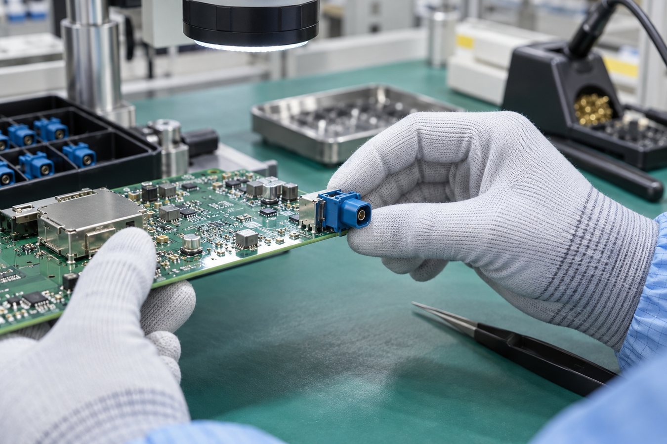
The first article should confirm code direction, seating height, clean mating surfaces, solder quality, and unobstructed cable latching. Shield pins provide both mechanical retention and the RF return path, so incomplete soldering can affect strength and signal performance.
Accepted photos, dimensions, solder criteria, and process settings should then move into the work instruction. Mixed builds that reflow electronics and selectively solder the connector also need a defined sequence and suitable fixtures. See our mixed-technology PCB assembly service for the related assembly approach.
Inspection and RF Testing for a FAKRA Connector PCB
Each inspection method answers a different question.
| Evidence | What it proves |
|---|---|
| Incoming inspection and FAI | Correct manufacturer, part number, code, lot, and orientation |
| Visual inspection, AOI, or X-ray | Seating, visible joints, hidden solder, or barrel fill as applicable |
| Bare-board electrical test and impedance coupon/TDR | Correct copper network and controlled PCB transmission line |
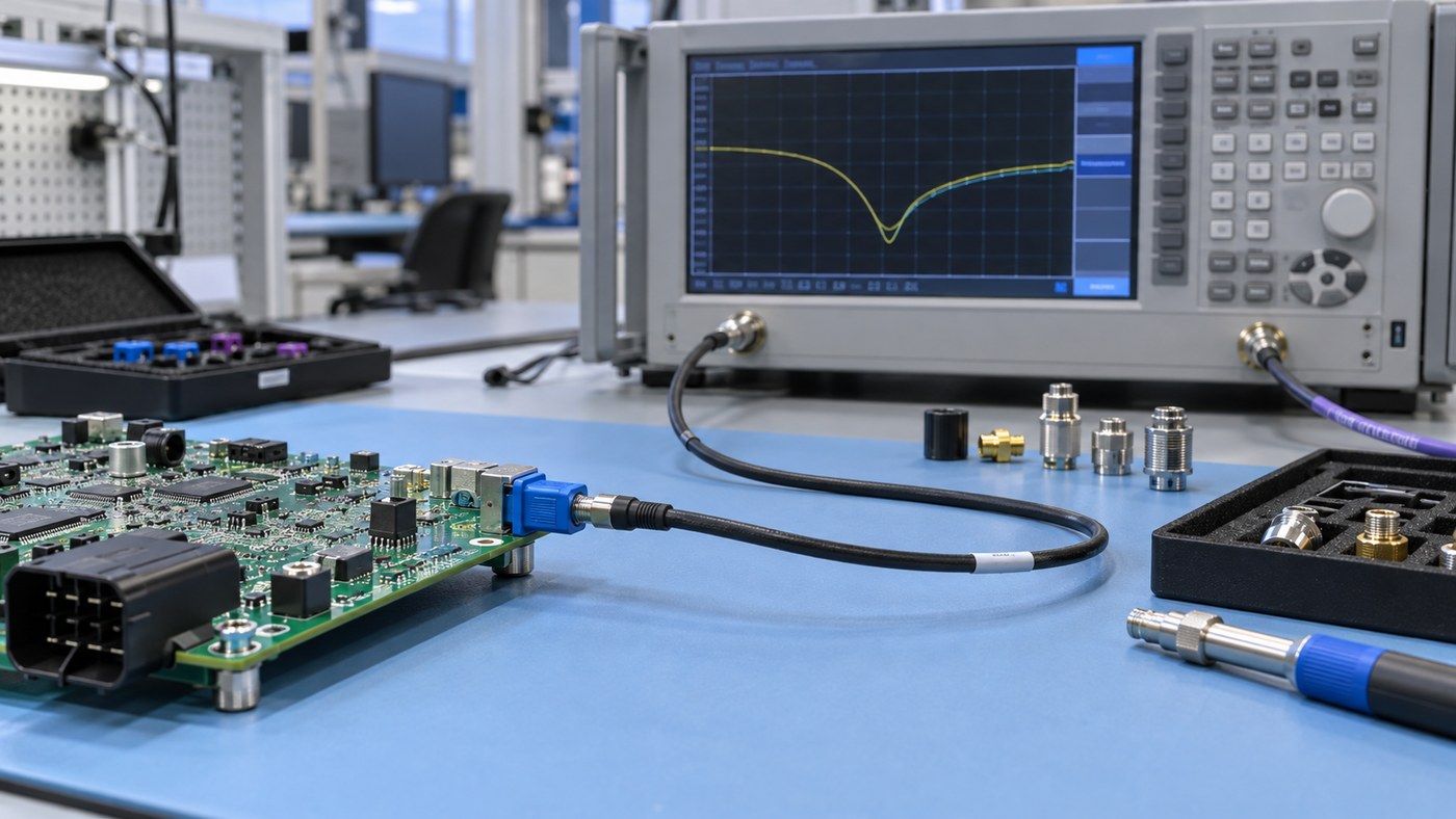
| Calibrated VNA measurement | S11/return loss and S21/insertion loss of the defined connectorized path |
AOI cannot measure impedance, and continuity testing cannot reveal a launch that is electrically connected but badly mismatched. Pull or retention testing should be limited to qualification or designated first-article samples when required by the released test plan.
An RF report should identify the sample, fixture, calibration method, reference plane, frequency sweep, and pass/fail limits. Without those details, two VNA plots are not directly comparable.
How to Source a FAKRA PCB Connector for PCBA Production
Specify the connector at full-part-number level. The BOM should identify the manufacturer, code/color, RF gender, orientation, PCB termination, packaging, and approved mating part. It should also state whether alternates are prohibited or require written approval.
Do not approve a substitute because it has the same color or distributor description. Recheck the mechanical key, mating interface, footprint, shield-pin pattern, height, sealing, frequency rating, soldering process, packaging, and qualification status.
Use an authorized supply channel and retain the connector lot/date code, required compliance documents, and change notifications. EBest Circuit can review availability and manufacturing compatibility, while the customer approves changes affecting the RF channel or vehicle interface.
How EBest Circuit Supports FAKRA Connector PCB Manufacturing
EBest Circuit turns an approved FAKRA interface into a controlled PCB and PCBA manufacturing package.
- Before production: We cross-check the connector drawing, footprint, mating cable, enclosure direction, stackup, soldering route, and test requirement.
- For the first article: We coordinate controlled-impedance PCB fabrication, approved sourcing, the documented assembly process, seating and solder inspection, bare-board testing, and impedance records. Fixture-based RF testing may be added only after EBest Circuit confirms the required equipment and test capability, and the customer approves the fixture, calibration method, reference planes, sweep, and acceptance limits.
- For repeat orders: The connector lot, PCB revision, assembly records, inspection results, and approved changes remain linked to the production batch.
EBest Circuit’s owned PCB and PCBA facilities, ISO 9001 and IATF 16949 quality systems, and prototype-to-repeat-production support help reduce handoffs. Pin-in-paste, conventional through-hole, and SMD processes can be planned from the released drawing. Press-in connector or housing designs require a separate review of the chassis interface, insertion tooling, force window, PCB-terminal method, and factory capability.
Send the connector and PCB package to sales@bestpcbs.com for a project-specific review.
FAQs About FAKRA PCB Connectors
What does FAKRA mean?
FAKRA comes from the German term Fachkreis Automobil and identifies a standardized family of keyed automotive coaxial connectors.
Is FAKRA Z universal?
Z is the neutral mechanical key, but gender, interface family, footprint, termination, frequency rating, and sealing must still match.
Does each FAKRA color have one fixed application?
No. Colors identify mechanical codes, while application assignments can differ between European, USCAR, and individual OEM conventions.
Are FAKRA connectors waterproof?
Only specified sealed versions provide environmental sealing, usually when correctly mated with the approved counterpart.
Do FAKRA connectors require special crimping tools?
Crimp-terminated cable contacts require approved stripping, crimping, and inspection tooling. PCB-mounted versions follow the through-hole soldering, pin-in-paste reflow, or SMD process specified in the product drawing. A separate press-in contact or housing feature, where used, must follow its own chassis and PCB-terminal instructions.
Can straight and right-angle FAKRA connectors share one PCB footprint?
Do not assume so. Center-pin location, shield posts, locating features, and housing datum can change even within one manufacturer’s range.
If your FAKRA PCB connector project is ready for prototype or repeat production, send the exact connector drawing, PCB files, mating information, and test limits to sales@bestpcbs.com. EBest Circuit can review the component, RF PCB, assembly, and acceptance requirements before production release.