A current divider splits an input current among branches that share the same two nodes. In an ideal resistive circuit, each branch current is inversely proportional to its resistance. On a PCB, the calculation remains useful, but resistor tolerance, copper resistance, connector loss, temperature and measurement loading can change the actual result.
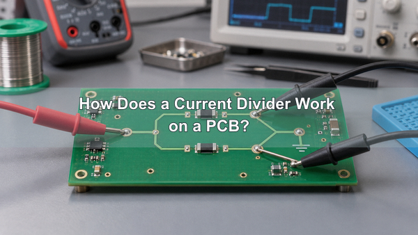
What Is a Current Divider?
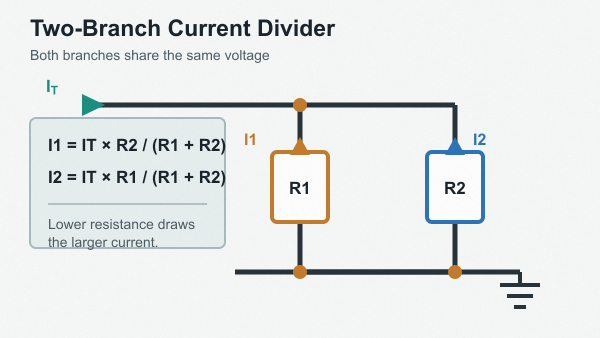
A current divider is a parallel network in which the source current separates into two or more branch currents. Because every branch is connected across the same pair of nodes, each branch has the same voltage. Ohm’s law then determines how much current flows through each branch.
A lower resistance draws a larger share of the total current, while a higher resistance draws a smaller share. Equal resistances divide the current equally. Kirchhoff’s current law provides the final check: the sum of the branch currents must equal the current entering the node.
How Does a Current Divider Work?
Assume a source supplies total current IT to several parallel resistors. Each resistor sees the same branch voltage V. The branch current is V/R, so a branch with twice the conductance receives twice the current.
The network does not create or consume current at the junction. It only distributes the source current according to branch admittance. This is why the rule applies to true parallel branches, not to components that merely look side by side on a schematic or PCB.
What Is the Current Divider Formula?
For N parallel resistors, the current divider formula for branch k is:
Ik = IT × (1/Rk) / Σ(1/Rn)
The same relationship can be written with equivalent resistance:
Ik = IT × Req / Rk
For two resistors, the current divider rule becomes:
I1 = IT × R2 / (R1 + R2)
I2 = IT × R1 / (R1 + R2)
The opposite resistor appears in the numerator because current division is inverse to resistance. Using R1 in the numerator for I1 is a common calculation error.
How Is the Current Divider Rule Derived?
Start with the equivalent resistance of the parallel network. The common branch voltage is V = ITReq. Applying Ohm’s law to branch k gives Ik = V/Rk. Substituting the common voltage produces Ik = ITReq/Rk.
This derivation explains the required conditions. The branches must share the same voltage, the total current must be known, and each branch must have a defined resistance or impedance. If a branch contains a nonlinear device, its current cannot be predicted from one fixed resistance without an operating-point model.
How Do You Solve a Current Divider Example?
Consider a 12 mA source feeding R1 = 2 kΩ and R2 = 4 kΩ in parallel. The two-resistor formula gives:
- I1 = 12 mA × 4 kΩ / (2 kΩ + 4 kΩ) = 8 mA
- I2 = 12 mA × 2 kΩ / (2 kΩ + 4 kΩ) = 4 mA
The 2 kΩ branch receives twice the current of the 4 kΩ branch. The result also passes the Kirchhoff check because 8 mA + 4 mA = 12 mA.
How Do You Calculate Current Division with Three Resistors?
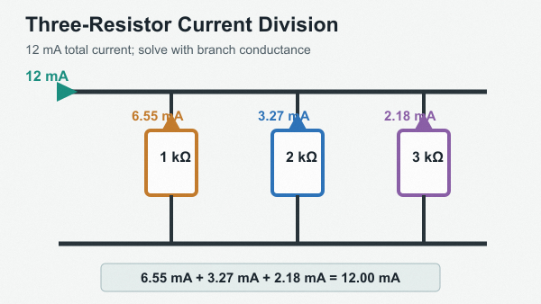
For three or more branches, the conductance form is less error-prone than repeated two-branch reductions. With a 12 mA source and parallel branches of 1 kΩ, 2 kΩ and 3 kΩ, the total conductance is 1.833 mS.
| Branch | Resistance | Calculated current |
|---|---|---|
| I1 | 1 kΩ | 6.55 mA |
| I2 | 2 kΩ | 3.27 mA |
| I3 | 3 kΩ | 2.18 mA |
The rounded values add to 12.00 mA. A current divider calculator can speed up this arithmetic, but the input topology and units still need to be checked before accepting its result.
Current Divider vs Voltage Divider: What Is the Difference?
A current divider uses parallel branches and determines branch current from the total current. A voltage divider uses series elements and determines a node voltage from the applied voltage. Both follow Ohm’s law, but they answer different design questions.
| Feature | Current divider | Voltage divider |
|---|---|---|
| Connection | Parallel branches | Series elements |
| Shared quantity | Voltage across every branch | Current through every element |
| Calculated quantity | Branch current | Element or node voltage |
| Distribution | Inverse to resistance | Proportional to resistance |
| Loading concern | Added branches change total conductance | A load changes the lower-leg resistance |
Can the Current Divider Rule Be Used in AC Circuits?
Yes, but resistance must be replaced by complex impedance or conductance. For AC branches, Ik = ITYk / ΣY, where Y is admittance. The branch currents can have different phase angles as well as different magnitudes.
At low frequency, an ideal resistor model may be sufficient. At higher frequency, capacitor ESR and ESL, inductor resistance and self-resonance, trace inductance, pad capacitance and connector geometry can affect the division. The result should then be checked with an impedance model or circuit simulation rather than a DC-only formula.
When Should You Use a Current Divider?
The rule is useful whenever a known current enters parallel branches with predictable impedance. Typical tasks include estimating shunt current, selecting a bypass path, analyzing transistor bias networks, checking pull-down paths and calculating how current is shared among resistive loads.
- Current sensing: estimate the portion of current passing through a known shunt branch before checking amplifier input and Kelvin-routing errors.
- Bias networks: calculate branch currents around an operating point when the connected device can be represented by an appropriate small-signal or DC model.
- Protection and discharge paths: determine how current divides through parallel resistors, clamps or bleeders under the defined condition.
- High-current power paths: make an initial sharing estimate, then include copper, via, connector and thermal resistance. Our heavy copper PCBs can support higher-current routing, but copper thickness alone does not guarantee equal sharing.
The ideal rule should not be used to assume that bare LEDs, batteries, MOSFETs or other nonlinear devices will share current equally. Their I-V curves and temperature behavior require a suitable balancing method.
What Causes Current Divider Errors on a PCB?
The schematic formula treats interconnects as ideal. A manufactured board adds series resistance and temperature-dependent effects to each branch. The error becomes important when branch resistance is low or the required ratio is tight.
| Error source | How it changes the result | Design response |
|---|---|---|
| Resistor tolerance and TCR | Changes the intended resistance ratio | Use tolerance analysis and matched networks where justified |
| Copper traces and vias | Add unequal series resistance | Balance geometry and calculate the complete path |
| Connector and contact resistance | Creates load-dependent branch error | Include interfaces in the resistance budget |
| Self-heating | Changes resistance during operation | Check power rating, derating and thermal coupling |
| Measurement loading | Adds another branch or lead resistance | Model the instrument and use suitable probing |
For a precision ratio, calculate worst-case branch current with resistor tolerance, temperature coefficient and expected copper resistance. A nominal calculation alone cannot define an acceptance limit.
How Should a Current Divider Circuit Be Laid Out?
Keep the electrical symmetry that the calculation assumes. Route matched branches from the same source node, avoid sharing a narrow neck before only one branch, and keep return paths comparable. If a small shunt voltage is measured, route the sense pair separately from the load-current path.
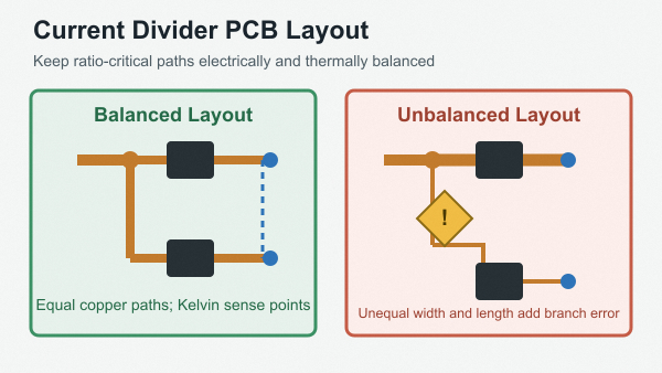
- Place ratio-critical resistors close together so their thermal environment is similar.
- Use a common node with balanced copper geometry for branches that should share current.
- Provide enough copper and vias for current capacity without changing only one branch resistance.
- Keep high-current switching loops away from sensitive current-sense traces.
- Use Kelvin connections when trace or terminal voltage drop would corrupt a shunt measurement.
Standard control circuits are commonly built on FR4 PCBs. Compact controllers may use HDI PCBs to shorten sense routes and place components tightly, but the chosen stack-up and via structure must still preserve the intended current path.
How Do You Test a Current Divider Circuit?
First verify the installed resistor values and the branch topology. Apply the specified source current, measure each branch under the intended load, and confirm that the measured currents sum to the source current within instrument and component tolerances.
- Measure resistance with the circuit unpowered when parallel paths will not distort the reading.
- Apply a controlled source current and record the common branch voltage.
- Measure branch current directly or calculate it from a verified shunt voltage.
- Repeat at relevant load and temperature conditions.
- Compare measured ratios with worst-case calculated limits, not only nominal values.
Probe placement matters. Long ground leads, contact resistance and a meter inserted in series can change a low-resistance branch. For assembled boards, our PCB assembly services can combine component inspection with customer-defined electrical or functional tests when limits and fixtures are provided.
Current Divider FAQs
Does Current Always Split Equally at a Junction?
No. Current splits according to branch impedance. It is equal only when the branch impedances are equal under the operating condition.
Is a Parallel Circuit a Current Divider?
A parallel network acts as a current divider when current enters the common node and separates among the branches. The rule applies because the branches share the same voltage.
Can You Use the Current Divider Rule for Series Circuits?
No. Series elements carry the same current. Use the voltage divider rule to calculate how the applied voltage is distributed across series impedances.
Why Does the Smaller Resistor Carry More Current?
Every parallel branch has the same voltage. Ohm’s law, I = V/R, therefore gives a larger current for a smaller resistance.
What Files Are Needed for PCB Fabrication and Assembly?
At EBest Circuit (Best Technology), we manufacture bare PCBs and provide assembly for current-divider, current-sense and control circuits. For a useful engineering review, send Gerber or ODB++ data, drill files, stack-up requirements, the BOM with resistor tolerance and TCR, pick-and-place data, assembly drawings, quantity and test requirements.
For precision or higher-current designs, also identify the source-current range, required branch ratio, allowable error, operating temperature, copper-current requirement, shunt value, Kelvin points and acceptance limits. We can review standard FR4, HDI or heavy-copper construction and assembly details against the actual design; manufacturability and test scope remain subject to the released files.
A calculated current divider becomes a repeatable PCB assembly only when the complete resistance path, thermal conditions and verification method are controlled. Send the design package to sales@bestpcbs.com for fabrication and assembly review.