PCB manufacturing PCB manufacturing
Home > Blog

BGA X-Ray Inspection

Turnkey IPC Class 3 PCB Assembly Services with BGA X-Ray Inspection
Monday, November 2nd, 2026

IPC Class 3 PCB assembly is intended for electronics that must keep running or respond on demand when failure would have serious consequences. A Class 3 build can put three different inspection problems on one board: exposed controller leads, solder balls under a BGA and connector pins inside plated holes.

At EBest Circuit, engineers with 20 years of PCB and PCBA experience review your design before we release it to our own PCB and assembly factories. You receive a design-for-manufacture (DFM) report and a BOM optimization list. For a fine-pitch BGA, that review can flag a footprint mismatch before parts are ordered and identify hidden joints that need X-ray inspection. Send your assembly drawing and BOM to sales@bestpcbs.com for an engineering review and turnkey quote.

IPC Class 3 PCB assembly

Which Products Need IPC Class 3 PCB Assembly?

Flight control computers, ventilator controllers and railway signaling boards are examples of products that may require IPC Class 3 PCB assembly. The common requirement is that the board must keep working without interruption or respond reliably at the moment it is needed.

Application Examples of boards and equipment
Aerospace Flight control computers, satellite telemetry boards
Defense Radar signal processors, tactical radio controllers
Life-support and implantable devices Ventilator controllers, pacemaker pulse generators
Diagnostics and patient monitoring MRI acquisition boards, patient-monitor alarm boards
Automotive safety Airbag control units, electronic braking controllers
Rail transport Signaling interlocks, onboard brake controllers
Nuclear and grid protection Reactor trip controllers, protective relay boards
Industrial safety Emergency-stop controllers, safety interlock boards
Remote or harsh environments Subsea instrument controllers, downhole telemetry boards

The product owner specifies the IPC class for the individual assembly. For example, a patient monitor’s alarm board and a service accessory for the same monitor can have different acceptance requirements.

IPC Class 2 vs Class 3 for Solder Joints

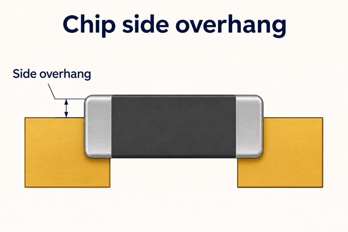
The same placement offset can satisfy a Class 2 limit and exceed a Class 3 limit. Consider a rectangular chip whose termination extends sideways beyond its pad. Under the side-overhang criterion in IPC-A-610E §8.3.2.1, the narrower of the termination and pad determines the reference width.

For a 0.40 mm termination on a 0.50 mm pad, the reference width is 0.40 mm.

Side overhang Class 2 Class 3
Maximum, % of reference width 50% 25%
Maximum for this chip 0.20 mm 0.10 mm
Measured at 0.15 mm Within limit Exceeds limit

The 0.15 mm offset matters even if the board powers on. This example illustrates one feature under revision E. Production acceptance follows the revision specified on the order and the criteria for the actual termination.
IPC Class 3 PCB assembly

How EBest Circuit Inspects Assemblies to IPC-A-610 Class 3

We match each inspection to the connection on the drawing. J-STD-001 covers soldering materials and processes. IPC-A-610 provides workmanship criteria for evaluating the finished assembly.

Connection Inspection focus
Gull-wing lead Side overhang, joint width, heel fillet
Through-hole pin Barrel fill, wetting, land coverage
BGA solder balls Alignment, bridges, void patterns

Visible leads and connector pins. Optical inspection can show a displaced lead or a bridge between exposed pins. On a through-hole connector, the solder fillet at the board surface shows wetting there. The amount of solder inside the barrel needs separate evaluation if it cannot be seen from that view.

Hidden BGA joints. X-ray can reveal a bridge beneath the package. A functional test can show whether the processor boots and communicates under the specified conditions. Where both are required, we agree on the packages to inspect, X-ray acceptance criteria, sampling and the records to retain for each lot or serial number.
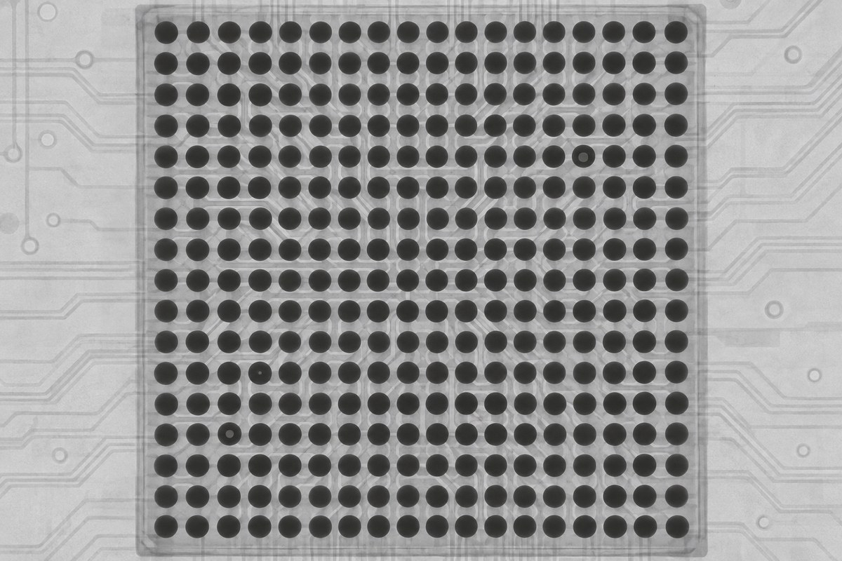
IPC Class 3 PCB assembly
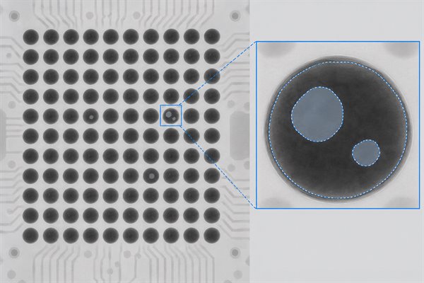
Illustrative X-ray view of a BGA solder ball array.

What Determines IPC Class 3 PCB Assembly Lead Time?

Our general turnkey PCBA planning reference is 10–12 business days from confirmed files and purchase order. For a Class 3 order, the ship date also depends on when the complete kit, first article and required tests are ready.

  • Parts availability. PCB fabrication and sourcing can run in parallel. If the processor arrives after the bare boards, its arrival sets the earliest SMT start. A missing through-hole connector can still hold up shipment after SMT is complete.
  • First-article approval. When the customer needs to review the first assembled board before the rest of the lot runs, that review belongs in the production schedule.
  • Test readiness. A fixture can be prepared during fabrication. If the fixture or released firmware arrives late, assembled boards may still have to wait for functional testing.

For a repeat order, an unchanged board revision and test procedure may allow the existing setup to be reused. A quote should distinguish the first-article ship date from the tested production-lot ship date.

What Drives IPC Class 3 PCB Assembly Costs?

The price depends on what the factory sets up once and what it must do for every board. That distinction is especially useful when comparing a prototype quote with a production quote.

  • Setup and tooling. A stencil or dedicated fixture can serve more than one batch if the design remains compatible. Spread the same fixture charge across 200 boards instead of 20, and its cost per board falls to one tenth.
  • Components and assembly. Every unit needs its own parts and assembly time. A board with through-hole power connectors requires a soldering operation after the surface-mount stage when that sequence is specified.
  • Inspection and records. Reviewing one BGA per board and retaining a serial-linked image takes more time than reviewing a sample from the lot. Two quotes for the same BOM can therefore cover different amounts of inspection.

Case Study: IPC Class 3 Requirements for a Portable Diagnostic Device

A Mexico-based medical device manufacturer asked EBest Circuit to assemble a 12-layer HDI board for a portable diagnostic device. Its design combined 01005 components and BGAs. The order called for IPC-A-610 Class 3 workmanship and set a separate BGA void target of 3% or less for this project.

  • 01005 placement. With so little pad area available, control of the printed solder-paste deposit mattered before the components reached reflow.
  • BGA inspection. After reflow, we used 3D X-ray to examine voiding beneath the packages against the customer’s target.
  • Unit traceability. We captured process records in the manufacturing execution system so the customer’s quality team could trace an individual board’s production history.

This gave the customer two things to use in a later review: an inspection method for the hidden joints and a way to identify the assembly involved.

Get an IPC Class 3 PCB Assembly Quote

Email sales@bestpcbs.com with these details so we can price the build and identify what controls its ship date.

  • Board and assembly files. Gerber or ODB++, BOM with manufacturer part numbers, placement data and the released assembly drawing.
  • Acceptance and testing. Applicable standards, revisions and class. Identify critical BGAs by reference designator and include any X-ray, firmware or functional test requirements.
  • Order scope. Prototype and repeat quantities, customer-supplied parts and target dates for first articles and completed lots.

We can then separate reusable tooling from the unit price and show which materials or tests affect delivery.

FAQs About IPC Class 3 PCB Assembly

Does a Class 3 bare PCB automatically qualify the assembled board as Class 3?

Bare-board acceptance covers the unpopulated PCB. Once components are fitted, their placement, solder connections and finished workmanship require a separate assembly specification. Identify both requirements when purchasing a turnkey build.

Which revision applies if an older drawing is still in production?

Use the revision invoked by the controlling order and drawing. If they disagree, resolve the discrepancy before production. Moving a legacy design to a newer revision requires agreement on the change.

Can prototypes and production boards use different acceptance classes?

They can when the project documents specify different requirements for each build. A prototype accepted to Class 2 can support firmware development, for example. Production qualification to Class 3 requires evidence from a build evaluated to those criteria.

Does an inspector’s IPC training certificate cover my shipment?

The certificate identifies the person’s training or qualification within its stated scope. Evidence for a shipment must relate to the assemblies supplied, their revision and the acceptance requirements on that order.

Can we approve an alternate component after the first article?

An alternate may change the termination geometry, moisture handling or reflow limits even when its electrical function is equivalent. The engineering review determines which assembly settings, inspection programs or first-article checks need updating before the alternate enters production.

We support prototypes and small batches so your team can validate the design before committing to a production run. For eligible builds with parts and test requirements ready, we offer a 1.5-week PCBA turnaround. Our digital shop floor can retrieve recorded material and product batch details within five seconds, helping your quality team trace affected units if a component lot needs review. For your IPC Class 3 PCB assembly, email sales@bestpcbs.com with your first-article quantity and target date. We’ll quote the inspection coverage and confirm the earliest feasible ship date.

You may also like

What Is a BGA Void? Causes, Risks, and Prevention
Tuesday, October 6th, 2026

Finding a BGA void does not automatically mean the solder joint will fail, and it does not automatically justify rework. The decision depends on how much of the joint is affected, where the void sits, whether the pattern repeats, and which acceptance requirement governs the build.

A single percentage cannot answer all four questions. The useful path is to read the full X-ray pattern, separate measurement from acceptance, and then connect the result to paste deposition, reflow, moisture exposure, or PCB pad and via design. That turns an image into a decision instead of a reason to change several process variables at once.

BGA void, BGA package and X-ray inspection monitor showing hidden solder joint indications

What Is a BGA Void?

A BGA void is an unfilled cavity trapped inside a BGA solder joint after reflow. It can originate in the package solder ball, the printed solder paste, or the combined joint formed when the ball and paste coalesce during BGA soldering. Because the package hides the array, internal voids are normally assessed with X-ray inspection.

A void is not the same as a bridge, missing ball, nonwet open, or head-in-pillow condition. Those defects form differently and may require other views or tests. Confirm the defect type before calculating a void percentage or changing the assembly process. Record the indication first; make the acceptance decision only after its context is known.

What Causes BGA Voids to Form?

BGA voids form when gas, flux volatiles, or trapped air cannot escape before molten solder solidifies. The sources fall into four practical groups:

  • Material-related causes: paste chemistry, flux activity, moisture, oxidation, or contamination can add gas or interfere with wetting.
  • Printing-related causes: the shape and consistency of the paste deposit influence trapped air, solder volume, and the route available for gas to leave.
  • Reflow-related causes: the thermal profile determines when volatiles are released, how well the solder wets, and how long gas can escape before solidification.
  • PCB pad and via-related causes: land geometry, via-in-pad construction, and local copper distribution alter solder flow, heat transfer, and solder wicking.

Several groups can act together. The X-ray pattern narrows the search; paste records, SPI, thermal data, and PCB information identify the actual cause.

Are BGA Voids Always a Reliability Problem?

No. A BGA void is an internal cavity, not an automatic declaration that the solder joint is defective. Some joints with voiding remain serviceable, while others deserve attention because of their geometry and the product’s operating conditions.

An X-ray indication should therefore trigger an engineering evaluation rather than immediate rework. Removing a BGA adds another thermal cycle and can introduce pad, package, or alignment damage, so the rework decision should follow the applicable acceptance requirement and the actual risk to the assembly.

The lower-risk response is to document the indication, review the governing requirement, and compare the complete array before deciding whether further testing or rework is justified.

Which BGA Voids Are More Likely to Affect Reliability?

Voids are more likely to affect reliability when they remove a large part of the joint, sit near a critical interface, form a cluster, or recur at stressed ball locations. The same void geometry deserves more attention in assemblies exposed to strong mechanical or thermal loads.

Pay closer attention when:

  • Large area loss: a single void occupies a large part of the joint.
  • Critical location: the void is close to an interface or likely crack path.
  • Clustered geometry: several nearby voids reduce the effective solder area in one region.
  • Repeatable coordinates: the same ball locations show voiding across multiple boards.
  • High service load: the assembly faces vibration, bending, drop, or repeated thermal cycling.

Do not decide from total percentage alone. Compare the largest void, its location, the distribution across the array, and the product’s expected loads. A higher-risk pattern calls for closer verification, not an automatic conclusion.

How Are BGA Voids Detected and Measured?

BGA voids are normally detected by X-ray inspection for PCB assembly, where they appear as lighter regions inside the darker solder-joint projection. The first task is to confirm that the indication is inside a joint and then read it in the context of the complete array.

  • Size: compare the largest individual void and the total affected area rather than counting bright spots alone.
  • Location: note whether the void is central, near an interface, or aligned with a via or other PCB feature.
  • Pattern: distinguish one isolated indication from clusters, rows, corners, or a region that shares the same thermal or design influence.
  • Repeatability: compare the same ball coordinates across more than one board to separate a random event from a fixed process or PCB factor.

Inspect the whole array before enlarging one joint. Use a consistent exposure and orientation, record the ball coordinate, and retain the original image. That makes later comparisons traceable and reduces the chance that one unusual joint is mistaken for a package-wide trend.

Projected void area ratio = total projected void area inside the joint ÷ projected solder-joint area × 100%

For example, 0.050 mm2 of visible voiding inside a 0.503 mm2 projected joint area gives about 9.9%. The result can change with image angle, magnification, contrast, and the selected boundary, so comparisons need the same setup and method.

BGA void, X-ray view of a BGA array with an enlarged solder joint showing projected void area

The measurement is not an automatic pass or fail. X-ray describes projected geometry; acceptance still depends on the governing requirement, the void’s position and distribution, and the product risk.

What BGA Void Percentage Is Acceptable?

There is no single BGA void percentage that can serve as a universal pass/fail limit. Acceptance follows the document and revision specified for the project, together with the measurement method and the joint condition shown by the X-ray.

A practical decision follows this order:

  1. Identify the governing requirement. The customer specification, drawing, contract, or applicable IPC document establishes the acceptance basis for that build.
  2. Confirm the measurement method. The reported ratio should be traceable to a defined X-ray view, threshold, and projected joint boundary.
  3. Review the largest individual void. This distinguishes one dominant cavity from the same total area spread across smaller voids.
  4. Consider location and distribution. Interface-adjacent, clustered, or repeated voids may justify further review even when the total percentage is unchanged.
  5. Compare the array and production lot. A stable isolated result and a worsening repeated pattern should not receive the same process response.

Figures such as 10%, 20%, or 25% are not universal BGA acceptance limits. A value quoted online may come from another document revision, product class, package type, or measurement convention. Use a numerical limit only when the project requirement makes it applicable. If the build documents do not specify one, settle the acceptance basis and review authority before production rather than inventing a threshold after inspection.

How Do Solder Paste and Stencil Printing Affect BGA Voids?

Solder paste controls volatile release and wetting, while stencil printing determines the volume and shape of each deposit. Paste that is beyond its storage, conditioning, or floor-life limits can behave differently; moisture exposure or contamination can add gas or disrupt wetting. Printing variation can then change both solder volume and the escape path.

Irregular results from ball to ball often justify checking SPI volume, alignment, aperture release, stencil cleanliness, and paste handling before changing the oven. A consistent footprint-wide pattern points more strongly toward paste chemistry, aperture design, or a stable print setup. Confirm the correction when SPI stability and the next X-ray pattern improve together.

How Does the Reflow Profile Affect BGA Voiding?

The reflow profile affects BGA voiding by controlling when volatiles are released, when solder coalesces, and how long gas can escape. Aggressive heating can trap gas after coalescence begins; insufficient time above liquidus can limit wetting; excessive heat can exhaust the flux or increase oxidation and warpage risk.

Widespread voiding may reflect a profile that does not suit the paste and board mass, while one row or corner may expose a temperature difference across the package. Measure the real ramp, soak, time above liquidus, peak, and temperature spread with thermocouples at representative locations. Adjust within material and component limits, then compare the next build using the same X-ray method.

How Do PCB Pad and Via Designs Contribute to BGA Voids?

PCB pad and via designs contribute to BGA voiding when they change solder volume, wetting, heat flow, or the path into which molten solder can wick. Open or incompletely filled via-in-pad structures can pull solder away from the joint and leave an indication aligned with the via.

Voids that recur at the same coordinates, follow via locations, or concentrate near different copper mass point toward a fixed board feature. Compare the X-ray with the land pattern and fabrication data, then verify via fill, cap, planarity, and pad dimensions on the delivered PCB. The actual construction, not the drawing alone, shows whether solder wicking or thermal imbalance is present. Check both design intent and delivered-board evidence before changing the assembly process.

How Can You Find the Root Cause of BGA Voids?

The fastest route to a likely BGA void cause is to match the X-ray pattern with the process or design evidence that could produce it. The image supplies a direction; SPI, thermal data, material history, and PCB information confirm or reject it.

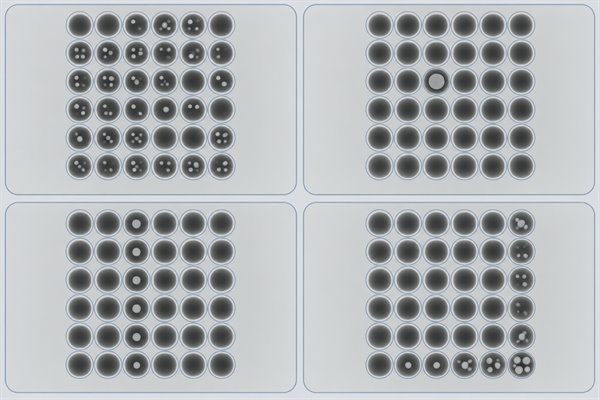
BGA void, four X-ray distribution patterns used to compare likely cause areas
X-Ray Pattern Likely Cause Area Check First
Many small voids Paste or reflow behavior Paste condition, SPI stability, and the measured thermal profile
One large isolated void Local printing or wetting SPI at that pad, pad surface condition, and contamination evidence
Voids aligned with vias Via-in-pad construction Via fill, cap, planarity, and evidence of solder wicking
One row or corner affected Thermal imbalance or warpage Temperature distribution across the BGA and board flatness
Same coordinates on many boards Fixed design or process factor Pad, via, copper, tooling, and repeatable process patterns

A pattern is a starting hypothesis, not a final diagnosis. Start with the broadest repeatable feature, because an array-wide change is usually more informative than the most visually dramatic joint. Then work through five practical moves:

  1. Check whether it repeats. Compare several boards and the same ball coordinates.
  2. Match the pattern to evidence. Review SPI, the measured profile, material history, and PCB features.
  3. Choose the strongest explanation. Predict which joints should change if that explanation is correct.
  4. Change one leading variable. Keep the other major conditions stable so the trial is readable.
  5. Recheck the same locations. Improvement supports the cause; no change means the next explanation should be tested.

How Can You Reduce and Prevent BGA Voids?

Prevent recurring BGA voids by holding proven material, printing, thermal, moisture, and PCB conditions stable and confirming that the improvement repeats.

  • Stabilize paste and printing. Keep paste within its handling limits, maintain the stencil, and use SPI to confirm consistent volume and alignment.
  • Profile the actual assembly. Use thermocouple data from the real board and BGA rather than copying an oven recipe from another product.
  • Control moisture and contamination. Follow the documented storage, floor-life, handling, cleaning, and any required baking limits.
  • Verify pad and via construction. Confirm that delivered boards match the corrected via fill, cap, planarity, and land geometry.
  • Use a repeat-build check. Inspect the same coordinates with the same X-ray setup on the next build and confirm that the improvement holds across the agreed sample.

One improved image is not enough. Treat the correction as proven only when the process evidence and X-ray result repeat. Higher-risk products may also need electrical, mechanical, or qualification testing because X-ray alone cannot predict field life.

FAQs About BGA Voids

Q1: Can a BGA pass functional testing and still have a hidden solder-joint problem?

A1: Yes. Functional testing confirms operation under the applied conditions, not the internal shape of every joint. A marginal connection may behave differently during bending, vibration, or thermal cycling, so test results and X-ray evidence answer different questions.

Q2: Should a BGA be reworked solely because voids appear on an X-ray?

A2: No. Rework adds thermal and handling risk. First confirm the defect type, applicable acceptance requirement, void location, and repeatability. An ambiguous image may need another view before the package is removed.

Q3: What information should a useful BGA X-ray report include?

A3: The report should make the decision reproducible. Include the assembly identity, BGA part number, lot, array orientation, ball coordinates, overview and detail images, measurement method, governing requirement, and disposition. Preserve the original images for later comparisons.

Q4: Can 2D X-ray reliably distinguish a void from head-in-pillow?

A4: Not in every case. A 2D image is a projection, so overlapping materials can hide an interface separation. Another X-ray view or physical analysis may be needed when the image and electrical symptom do not agree.

Q5: What should be checked after BGA rework?

A5: Review the complete reworked array. Check alignment, ball shape and collapse, bridges, opens, voiding, and regional differences. Compare with the earlier image when available, then complete the appropriate electrical or functional test.

Q6: When is destructive analysis justified for a suspected BGA void problem?

A6: It is justified when nondestructive evidence cannot resolve an important failure question. Cross-sectioning or dye-and-pry can confirm interface cracking, pad separation, intermetallic condition, or true void geometry when a sample can be sacrificed. Preserve the X-ray, electrical results, and build history first.

Conclusion

A BGA void should lead to an evidence-based decision, not automatic rework. Confirm the defect type, compare its size, location, distribution, and repeatability, measure it with a consistent X-ray method, and apply the requirement that governs the build. If the pattern repeats, change one likely cause at a time and treat the correction as proven only when the next build shows repeatable improvement.

Unsure whether a BGA void calls for rework or a process adjustment? Email sales@bestpcbs.com with the X-ray image and BGA part number. If available, include the Gerber or ODB++ files and the applicable acceptance requirement. EBest Circuit can review the pattern and help you determine what to verify before rework or the next build.

You may also like