PCB manufacturing PCB manufacturing
Home > Blog

Aluminum PCB Manufacturing

Aluminum Substrate PCB for Lighting Supplier | Custom LED PCBs
Thursday, October 29th, 2026

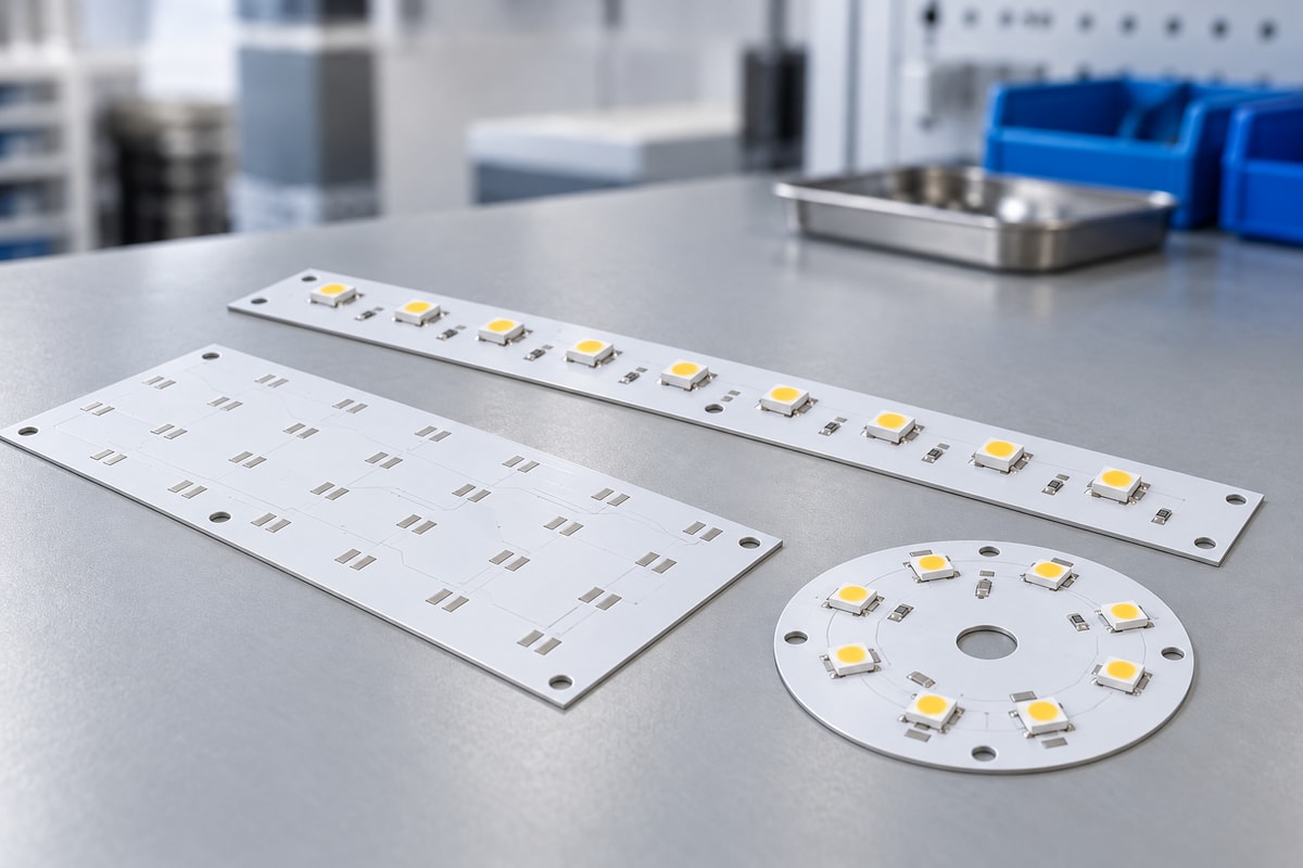
An aluminum substrate PCB for lighting supplier should help you turn an LED design into boards that fit your fixture, support its thermal requirements, and arrive ready for the next production step. For lighting manufacturers, that means dependable PCB fabrication, suitable materials, accurate mounting features, and assembly support when a bare board alone is not enough.

At EBest Circuit (Best Technology), we combine MCPCB manufacturing experience dating back to 2006 with component sourcing and PCB assembly. We support custom lighting boards from prototypes through production, bringing the board and assembly requirements into one coordinated order. Send your drawings and quantity to sales@bestpcbs.com to discuss a bare-board or assembled LED module quotation.

Aluminum substrate PCB for lighting supplier

Top 10 Aluminum Substrate PCB for Lighting Suppliers in China

China offers both online PCB ordering services and manufacturers supporting custom metal-core boards and assembly. The ten suppliers below provide relevant aluminum PCB services. This is a sourcing shortlist based on product and service fit; the order does not represent an independent performance ranking.

Supplier Relevant Products and Services
EBest Circuit (Best Technology) Custom MCPCBs, component sourcing, and LED assembly
PCBWay Online aluminum PCB quotes; material/finish options
JLCPCB Single-layer MCPCBs in defined configurations
ALLPCB Aluminum PCBs within specified machining limits
PCBasic Aluminum PCB fabrication and PCBA services
Viasion Single-sided, double-sided, and multilayer MCPCBs
RayMing / RAYPCB LED arrays and linear-lighting PCB assembly
Hitech Circuits Two-layer and COB aluminum PCB constructions
Venture Electronics Aluminum PCB fabrication and stackup support
WellPCB Aluminum PCB design review and assembly

A standard single-layer LED board and a custom assembled lighting module require different levels of support. At EBest, our emphasis is on coordinating the PCB construction, mounting features, component procurement, and assembly around the customer's lighting design.

Who We Supply: Aluminum PCB for LED Lighting OEMs

Our aluminum PCB service is suited to businesses that build lighting products, LED modules, or assemblies for other brands. The supply scope can match the stage your team wants to handle internally.

  • Lighting OEMs and ODMs: Boards shaped for their housings, optics, and heat sinks, with a manufacturing route that can continue into repeat production.
  • LED Module Manufacturers: Consistent circuit layouts, mounting features, and component placement across a module family.
  • Industrial and Outdoor Lighting Brands: Boards matched to the thermal and mechanical requirements of high-bay lights, street lights, floodlights, and related fixtures.
  • Specialist Lighting Developers: Support for compact optical layouts and application-specific assembly details, including medical-lighting modules.
  • Contract Manufacturers and Lighting Solution Companies: We supply bare aluminum PCBs for their own SMT lines or assembled boards to simplify integration.

For a team with established LED assembly capacity, we can supply the fabricated boards. For a team managing product development and final fixture assembly, we can combine PCB fabrication, component sourcing, and SMT work.

Custom Aluminum PCB Manufacturing Capabilities for Lighting Projects

We manufacture custom aluminum PCBs around the electrical layout and mechanical drawing. Board thickness, copper weight, dielectric selection, and outline processing are reviewed together so that a change intended to improve one feature does not create a problem elsewhere.

Manufacturing Item Specification
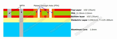
Construction Single-sided; double-sided; single-sided two-layer
Board thickness 0.8–3.0 mm routine
Outer-layer copper 1–3 oz; ≄3 oz requires confirmation
Dielectric thermal conductivity 1, 2, 3 W/mĀ·K
Dielectric thickness 100–110 µm; specified Boyu/Juding constructions
Outer-layer line width / spacing, 1 oz 0.20/0.20 mm minimum
Outer-layer line width / spacing, 2 oz 0.25/0.25 mm minimum
Non-plated finished hole Ø1.0 mm minimum; diameter tolerance ±0.05 mm
Outline tolerance ±0.15 mm routine; ±0.10 mm upon review
Solder mask White, black, green; other colors upon review
Surface finish HASL, OSP, immersion gold

Higher dielectric conductivity requires a material enquiry. Other material systems need their own dielectric-thickness specification. Line width and spacing are drawing minima; hole-position tolerances are specified separately from hole-diameter tolerances. Routing and insulation follow the selected stackup, and the surface finish follows assembly requirements.

These options are reviewed as a complete construction; they are not a promise that every process limit can be combined on one board.

Copper weight directly affects routing space. Moving from 1 oz to 2 oz changes the routine line and spacing requirement above. Reviewing this before fabrication helps preserve the intended LED layout without relying on an unsuitable manufacturing assumption.

High Power LED Aluminum PCB Solutions

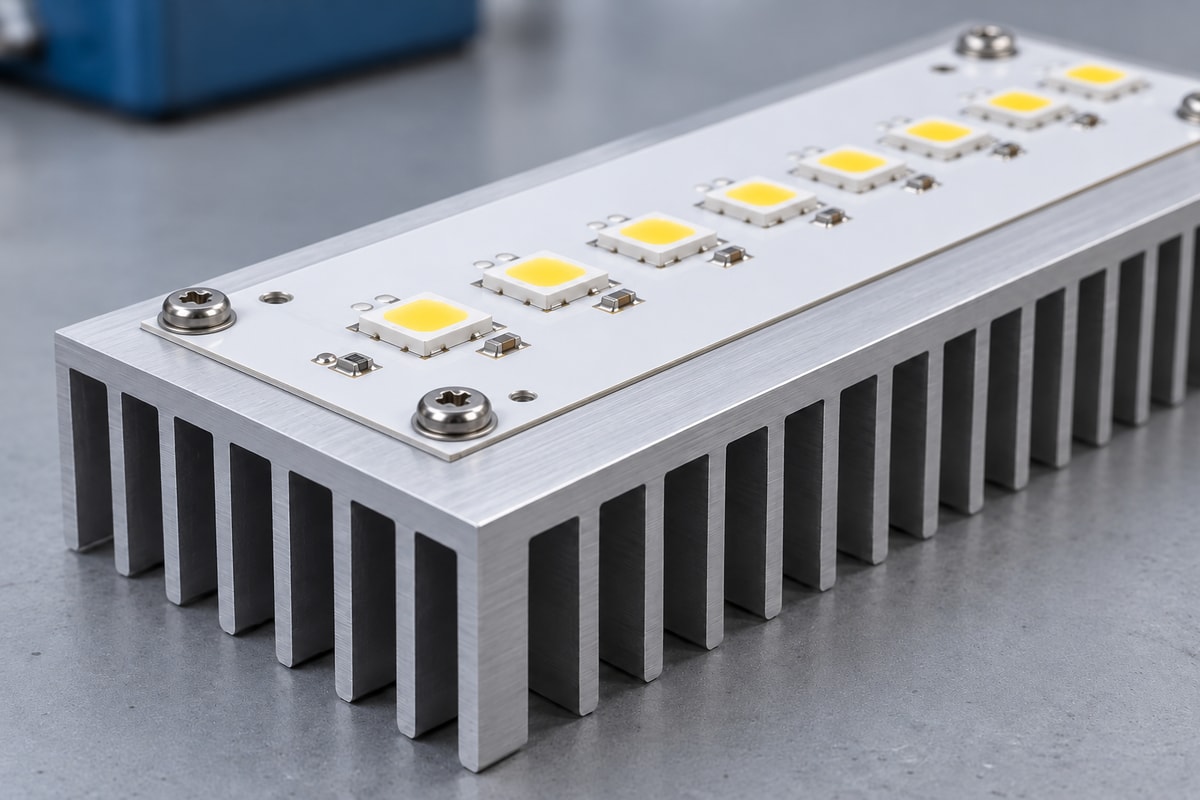
For a high power LED aluminum PCB, the useful improvement is a lower-resistance thermal path from the LED into the cooling structure. Increasing the dielectric conductivity can help, but the dielectric thickness, solder interface, copper layout, and heat-sink contact also affect the result.

For the same dielectric thickness and heat-transfer area, a higher-conductivity dielectric reduces that layer's thermal resistance. It does not reduce the entire module's thermal resistance by the same proportion, because the other interfaces remain in the heat path.

Construction Main Advantage Selection Constraint
Aluminum PCB, standard dielectric Balanced cost, weight, and thermal transfer LED heat load and insulation requirements
Aluminum PCB, higher-conductivity dielectric Lower dielectric thermal resistance Material cost, availability, and heat-sink contact
Copper-based or direct-thermal-path construction Suited to concentrated heat sources Cost, weight, isolation, and package compatibility

Copper-based and direct-thermal-path designs require construction-specific electrical-isolation and LED-package review.

Our MCPCB range lets us discuss alternatives when a compact LED array exceeds the practical limits of the proposed aluminum construction. We can review the board structure against the LED package and mounting arrangement before production. Final operating temperature is evaluated in the complete lighting assembly under its intended power and ambient conditions.
Aluminum substrate PCB for lighting supplier

LED PCB Assembly from Bare Boards to Lighting Modules

EBest Circuit provides aluminum PCB fabrication, LED component sourcing, SMT assembly, and agreed board-level testing. We can supply bare boards or assembled LED modules, giving your team one contact for manufacturing and assembly coordination.

  • PCB Fabrication and Assembly: We coordinate pad finish, panel handling, and mounting clearances with the assembly requirements to keep the fabricated board compatible with SMT and integration.
  • LED Sourcing and Binning: We source against the approved manufacturer and part number, including specified color-temperature, luminous-flux, or wavelength bins. Package size alone does not establish optical interchangeability.
  • SMT Process Adaptation: Reflow planning accounts for the aluminum board's thermal mass while respecting component process limits.
  • LED Polarity and Placement: Placement files and assembly drawings define LED orientation and position against the approved optical layout.
  • Testing and Module Delivery: Agreed board-level tests accompany the assembly scope, providing LED boards for the next integration stage. Final luminaire assembly and validation follow the project scope.
Aluminum substrate PCB for lighting supplier

Quality Control for LED Aluminum PCB Production

Quality control needs to protect the features that determine whether the board can be assembled, mounted, and operated as intended. Our manufacturing approach combines material and process control with inspection against the released design.

Electrical Integrity and Insulation: Opens-and-shorts testing verifies circuit continuity and separation; specified dielectric-withstand testing evaluates insulation under defined conditions. Test voltage and procedure must suit the board construction.

Mechanical Fit: Outline dimensions, mounting holes, slots, and finished edges affect fit with the housing or heat sink. Critical drawing dimensions form part of the inspection scope.

Assembly Condition: LED polarity, placement, solder joints, and cleanliness are addressed through agreed inspection and operating tests. Thermal or optical measurements are included when required by the project.

Repeat-Order Control: Approved materials, design revisions, and production records support investigation of variation between deliveries. They also help distinguish similar boards within a lighting product family.

Our Certifications for Aluminum PCB Manufacturing

Our certification portfolio includes ISO 9001:2015, ISO 13485:2016, IATF 16949, and AS9100D. These quality systems support OEM supplier evaluation and provide a structured basis for manufacturing control, traceability, and corrective action.

  • ISO 9001:2015: Quality management covering purchasing controls, process consistency, and customer requirements.
  • ISO 13485:2016: Quality-management support for medical supply chains, including medical-lighting projects within the certified scope.
  • IATF 16949: Automotive quality-management requirements for applicable manufacturing activities and supply chains.
  • AS9100D: Aerospace quality-management requirements for applicable manufacturing and customer programs.

UL, RoHS, and REACH: We support construction-specific UL requirements and product-relevant substance-compliance documentation. These are addressed separately from quality-system certification.

Our quality systems connect manufacturing process control with the documentation needed for customer supplier audits. We align the certificate entity, facility, and scope with the order; finished LED luminaire certification remains specific to the complete product.

Case Study: Custom Aluminum PCB for an LED Lighting Module

Application: A Surgical Lighting Module required an assembled LED board ready for installation in the customer's lighting system.

Manufacturing Challenges: LED positions needed to follow the optical layout, and mounting-hole positions needed to support mechanical fit. The project also required LED operation checks and coordination between board fabrication, component procurement, and assembly.

EBest Circuit Solution: We coordinated custom aluminum PCB fabrication, component sourcing, and SMT assembly under one order. LED placement followed the approved optical layout, critical mounting-hole positions were measured optically, and every LED received an operation check before shipment.

PCB Specifications:

Parameter Specification
Construction Single-sided aluminum PCB
Board Thickness 1.6 mm ±10%
Copper Weight 1 oz
Surface Finish Lead-free HASL
Solder Mask Black
Legend Gray

The customer received fabricated boards, sourced components, and completed SMT assembly in one coordinated delivery. This combined mechanical-fit control and LED assembly verification for the next integration stage.

Why Choose EBest Circuit as Your Aluminum PCB Supplier?

EBest is a strong fit when your lighting project needs custom PCB manufacturing and direct coordination with assembly. Our MCPCB focus dates back to 2006, and our service covers prototypes, production boards, component sourcing, and PCB assembly.

Custom Manufacturing Support: We review copper weight, dielectric construction, board outline, and assembly requirements together. This helps address manufacturing constraints before a compact fixture's mechanical design is released.

One-Stop PCB and Assembly: Fabrication questions are considered alongside the BOM and placement requirements, keeping the board and assembled module aligned within one coordinated project.

Prototype to Production: We support prototypes and production using the agreed construction, with quantities, material availability, assembly scope, and design changes reflected in the quotation.

Production Visibility: One-to-one support and online work-in-progress updates help purchasing and engineering teams track the build and resolve open questions.

MES Production Traceability: For production managed through our MES, we can retrieve linked material, product-batch, and production records in approximately five seconds. This helps OEM teams trace quality issues, manage batches, investigate anomalies, and review manufacturing history for repeat orders.

Certified Quality Management: Our ISO 9001, ISO 13485, IATF 16949, and AS9100D certifications support OEM supplier audits, manufacturing process control, and high-reliability projects within the applicable certified entity, facility, and production scope.

Whether you are launching a new LED module or reviewing an existing supply arrangement, we can quote the manufacturing scope your team needs—from a custom bare board to an assembled lighting PCB.

FAQs About Aluminum Substrate PCB for Lighting

Can I order prototypes before committing to production quantities?

Yes. We support MCPCB prototypes and production builds. A prototype order lets your team evaluate fit, assembly, and operation before releasing the production design.

What quantity should I include when requesting a quotation?

Include the initial build quantity and any expected repeat-order quantities. If your forecast is still developing, we can discuss separate prototype and production pricing rather than assume a fixed annual commitment.

Which files are needed for an aluminum PCB quotation?

For bare boards, send Gerbers, the fabrication specification, mechanical drawing, and quantity. For assembly, add the BOM, placement file, assembly drawing, and required tests. Available files are enough to start a preliminary discussion; the final build uses the agreed manufacturing package.

What affects the price most?

Board area and panel utilization, dielectric material, copper weight, machining, surface finish, and quantity all affect bare-board cost. Assembled-module pricing also includes components, assembly work, and the agreed inspection or testing scope.

Can you quote a replacement for an existing aluminum PCB?

We can review an existing design for manufacture. Gerbers and drawings provide the clearest basis; if only a sample is available, the engineering work needed to establish a production specification must be assessed separately.

How is delivery time determined?

The schedule follows the confirmed board construction, material availability, order quantity, and assembly requirements. For assembled orders, LED and other component availability can influence delivery as much as bare-board fabrication.

Work with an aluminum substrate PCB for lighting supplier that understands both board fabrication and LED assembly. With 20 years of PCB/MCPCB experience, EBest Circuit combines one-stop PCB manufacturing and SMT assembly with DFM engineering support to address manufacturing issues before production. Send your Gerber files, quantity, and technical requirements to sales@bestpcbs.com, and specify whether you need LED assembly. We will prepare a project quotation matched to your board construction and delivery scope.
You may also like

How to Choose the Right Metal Core PCB Manufacturer in the USA?
Friday, August 28th, 2026

Choose a metal core PCB manufacturer in the USA by matching the released construction, evidence package, quantity profile, and assembly scope to the factory that will build the order. A suitable manufacturer must be able to control the specified metal base, dielectric, copper, hole isolation, mechanical features, surface finish, and assembly interface as one design.

Shortlist suppliers by project fit and order evidence. Confirm who will manufacture the board, which material and process route will be used, what records will accompany the order, and whether those controls remain stable from prototype through repeat production. This keeps the selection process focused on a manufacturable, verifiable board rather than a long list of unrelated capabilities.

metal core PCB manufacturer in the USA, factory production floor with metal-core PCB panels and article title

What Should You Verify Before Shortlisting a Metal Core PCB Manufacturer Serving the USA?

Start with eight selection factors that determine whether a supplier can support the complete order. Remove candidates that cannot match the construction, evidence, quantity, or assembly scope before engineering time is spent on detailed quotations.

  • Relevant production history: Ask for evidence of work with the same MCPCB construction; standard single-sided aluminum experience does not qualify every metal-core build.
  • Metal-base range: Confirm the supported aluminum alloys, copper bases, thicknesses, and any special bonded or machined structures.
  • Thermal material control: Review dielectric grade, thickness, thermal performance, electrical isolation, and substitution policy together.
  • Custom construction capability: Match plated holes, multilayer bonding, pockets, routing, countersinks, and other drawing features to the proposed factory.
  • Order-level quality evidence: Define material, dimensional, electrical, isolation, and traceability records that will be released with the lot.
  • Assembly integration: If PCBA is required, check whether fabrication, soldering, heat-sink interfaces, inspection, and test ownership are coordinated.
  • Quantity fit: Confirm prototype support, intended production capacity, tooling, material availability, and repeat-order controls.
  • DFM response: A useful review identifies a specific drawing, material, isolation, machining, or assembly risk and returns a clear decision or question.

Which Metal Core PCB Construction Must the Manufacturer Prove?

Approve a supplier across the independent construction axes used by your design, because ā€œmetal core PCBā€ does not describe one manufacturing route. Separate the base material, circuit-layer structure, thermal-path architecture, electrical specialization, and mechanical integration before checking factory experience.

  • Base material axis: For aluminum, verify alloy, thickness, laminate, profiling, and panel control; for copper, add source control, weight, oxidation protection, machining, and handling.
  • Circuit-layer axis: A single-sided IMS route differs from a plated double-sided or multilayer route. Confirm hole isolation, bond sequence, registration, stackup limits, and internal-construction evidence as applicable.
  • Thermal-path axis: Distinguish a conventional dielectric-based path from a direct thermal path. Require a cross-section that shows both heat flow and electrical isolation.
  • Electrical-specialization axis: Power and LED IMS work emphasizes thermal and assembly control, while RF metal-backed work adds RF laminate handling, bond film, pockets, metal-carrier plating, dimensional datums, and finish compatibility.
  • Mechanical-integration axis: Separate a standard profiled base from a precision-machined carrier. Direct mounting to a heat sink, housing, or frame brings outline, holes, flatness, burr, pocket, and mounting surfaces into supplier qualification.

A supplier experienced with single-sided LED aluminum boards may still lack the plated, multilayer, direct-path, RF, or precision-machining controls required by another design. Ask the candidate to mark each axis as routine, conditional, or outside its current process window.

Which MCPCB Specifications Should You Confirm Before Choosing a Manufacturer?

Match the required stackup to a confirmed factory process window before approving a supplier. Best Technology publishes the following reference values in its single-layer MCPCB data and current product catalog. Use them for initial quotation screening. Only a build-specific review can confirm whether the required material, copper, geometry, thickness, layer count, and panel size can be produced together.

Capability item Best Technology reference range What to confirm for the order
Single-layer base material Aluminum, copper, or iron alloy Exact alloy, metal thickness, source, surface treatment, and whether the quotation uses the named material
Single-layer dielectric conductivity 0.8, 1.0, 1.5, 2.0, or 3.0 W/(mĀ·K) Material manufacturer and grade, dielectric thickness, thermal resistance, dielectric strength, and substitution rule
Copper weight 0.5, 1.0, 2.0, or 3.0 oz; up to 10 oz is listed Finished copper, minimum line/space at that weight, etching tolerance, and inspection method
Single-layer board thickness 0.5–3.0 mm Finished-thickness tolerance, flatness, mounting interface, and panel handling
General MCPCB layer count 1–10 layers Released cross-section, plated-hole isolation, lamination sequence, registration, and factory history with that structure
General MCPCB board thickness 0.8–5.0 mm Whether the requested thickness is valid with the selected layer count, metal base, copper, machining, and panel size
Minimum line/space 4/4 mil, or 0.10/0.10 mm Applicable copper weight, conductor tolerance, annular features, and production inspection basis
Maximum board dimension 610 Ɨ 1625 mm Usable panel size, array orientation, tooling margin, dimensional tolerance, flatness, and shipment protection

Send the same drawing, cross-section, quantities, and evidence requirements to every shortlisted supplier. Require the quotation to identify which values are routine, which require engineering review, and which combinations are unavailable at the named factory.

How Do You Verify the Manufacturer’s Quality and Traceability?

Reliability is demonstrated when the supplier can connect its quality system to your material, revision, lot, tests, and changes. Verify the certificate’s legal entity, site, and scope, then require order-specific material, revision, lot, test, and change records.

  • Site and scope: Check the legal entity, factory address, certificate scope, and actual operations used for the proposed order.
  • Incoming materials: Confirm how the metal base, thermal laminate, copper, solder mask, and finish materials are identified and released.
  • Process traceability: Ask how work orders, material lots, inspection results, deviations, and final shipments remain linked.
  • Electrical controls: Define the net test and any isolation requirement with the test method, voltage or limit supplied by the approved specification.
  • Dimensional controls: Identify which holes, cutouts, thicknesses, flatness points, and datums receive recorded inspection.
  • Nonconformance handling: Require segregation, disposition authority, corrective action, and customer notification for deviations that affect fit or performance.
  • Change control: Specify which material, process, factory, tooling, or sub-supplier changes require approval before the next lot.

The useful output is a qualification record that states what was verified, what remains conditional, and which documents will be delivered with production. Avoid approving a supplier from a logo sheet or questionnaire that is not connected to the actual build route.

How Do Material and Thermal Controls Affect Supplier Qualification?

Select a manufacturer whose routine materials and process controls match the metal base already justified by the thermal, mechanical, electrical, and cost design. Material selection comes first; supplier qualification then verifies the factory controls needed for that base and construction.

For an aluminum PCB project

  • Material identity: Confirm the base alloy, thickness, approved thermal laminate, dielectric thickness, and substitution limits.
  • Profiling control: Review routing, punching where applicable, V-scoring, burr control, and panel-to-board flatness.
  • Repeatability: Ask how thermal material and base-metal lots are controlled across prototype and production orders.

For a copper core PCB project

  • Base handling: Confirm copper-base weight, sourcing, oxidation protection, machining, and in-process handling.
  • Construction complexity: Review bonding, direct-path features, plated isolation, pockets, and registration with a cross-section.
  • Commercial impact: Ask the supplier to separate material, machining, tooling, yield-sensitive features, and assembly costs in the quote.

Do not assume that a high-volume aluminum IMS line can automatically produce a copper pedestal, plated metal-core, or RF metal-backed design. Qualification follows the released structure, not the broad MCPCB category.

Which Thermal Material Records Should the Supplier Provide?

Thermal material must be compared as a system because conductivity alone does not define heat flow or insulation performance. Two laminates with the same nominal W/m-K value can use different dielectric thicknesses and therefore produce different thermal resistance and electrical margins.

  • Thermal conductivity: Record the published value, test basis, and grade instead of accepting an unlabeled number.
  • Dielectric thickness: Confirm the finished or nominal thickness used in the thermal and isolation assessment.
  • Thermal resistance: Compare the full dielectric path and relevant area instead of using the material conductivity headline by itself.
  • Dielectric strength: Tie the required electrical isolation to an approved test method and design margin.
  • Material identity: Lock the manufacturer, grade, and accepted equivalent route when consistency matters.
  • Substitution policy: Require approval before a supplier changes grade, thickness, or source, even if the nominal conductivity is unchanged.
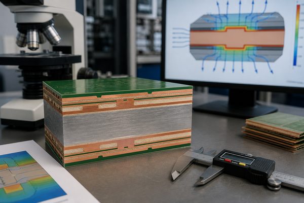
metal core PCB manufacturer in the USA, engineering review of copper dielectric and metal-base stackup

A strong candidate can return an approved stackup or material proposal that shows the copper, dielectric, and metal-base relationship. A weak candidate quotes ā€œ2 W/m-Kā€ or ā€œ3 W/m-Kā€ without naming the grade, dielectric thickness, isolation basis, or substitution boundary.

Can the Manufacturer Control Both Mechanical Fit and PCB Assembly?

Mechanical capability can disqualify an otherwise suitable MCPCB supplier when the board mounts directly to a heat sink, housing, or structural frame. Control the metal base as both a precision interface and a thermal layer.

  • Outline and datums: Define the dimensions that locate the board in the final assembly and the datum scheme used for inspection.
  • Slots and cutouts: State size, position, corner-radius, and burr requirements that affect clearance or fit.
  • Countersinks and countersunk holes: Specify side, angle, final diameter, depth, plating status, and relationship to the mounting hardware.
  • Routing and V-scoring: Confirm the separation method, residual thickness where relevant, edge quality, and component-to-edge constraints.
  • Flatness: Define the measurement condition and acceptance limit for the bare board or assembled board, whichever controls fit.
  • Mounting holes: Identify electrical isolation, annular clearance, tolerance, and any metal exposure requirement.
  • Surface contact: Mark heat-sink interfaces, keep-out areas, thermal interface material, and cosmetic or conductive surfaces on the drawing.

Ask the supplier which features are measured, with what fixture or datum, and whether the result is recorded. A drawing that says ā€œfit to heat sinkā€ without measurable criteria cannot produce a comparable supplier decision.

How Should Assembly Capability Be Verified?

Choose an assembly-capable manufacturer when fabrication choices and the soldering or mounting process share the same thermal and mechanical risks. The evaluation should connect the bare-board design to component placement, reflow, heat spreading, attachment, and test access.

  • High-power components: Review pad geometry, copper spreading, void-sensitive thermal pads, component limits, and inspection access for LEDs, MOSFETs, IGBTs, or similar devices.
  • Soldering process: Confirm the assembly profile is compatible with the laminate, finish, board mass, component set, and approved materials.
  • Heavy components: Check support, handling, depaneling, connector loads, and any secondary mechanical attachment.
  • Thermal interface: Define the heat sink, interface material, mounting hardware, torque source, cleanliness, and flatness assumptions when they are part of the order.
  • Inspection plan: Select AOI, X-ray, solder-joint inspection, or other methods only where the component and joint geometry make them useful.
  • Test ownership: State whether the supplier performs bare-board electrical testing, assembly inspection, programming, functional testing, or customer-defined verification.

If fabrication and assembly are split between suppliers, assign responsibility for material storage, solder-profile approval, thermal interface preparation, board damage, and failure analysis. The lowest bare-board price can lose value when those interfaces are unmanaged.

Which Tests Should Be Included in the Manufacturer’s Release Package?

The test package should verify the risks created by the released construction and drawing. Not every order requires every test, so define the method, sample or lot coverage, acceptance basis, and record before comparing suppliers.

  • Electrical test: Verify opens and shorts against the released net data using the agreed coverage and acceptance rules.
  • Isolation test: Apply the approved method where conductors, plated holes, mounting features, or direct-path structures must remain isolated from the metal base.
  • AOI: Use image inspection for applicable conductor, pad, and solder-mask features while recognizing that it does not replace electrical or internal construction evidence.
  • Dimensional inspection: Record critical outlines, holes, slots, countersinks, thicknesses, and datums that control assembly fit.
  • Flatness inspection: Define support condition, board state, measurement points, and limit before treating a result as comparable.
  • Material verification: Link the approved dielectric and metal base to the received lot and production traveler.
  • Microsection: Use it when plated, bonded, multilayer, or isolation features require internal construction evidence.
  • Solderability or finish evidence: Specify it when shelf life, assembly process, contact use, or a customer requirement makes the result relevant.
metal core PCB manufacturer in the USA, dimensional and electrical inspection of a finished board

For any temperature or thermal comparison, define input power, sensor position, ambient condition, heat sink, thermal interface material, mounting force, stabilization time, and board revision. Results measured under different conditions should not be used to rank suppliers.

Can the Manufacturer Maintain the Same Controls from Prototype to Volume?

A prototype supplier is suitable for volume only when the intended factory, material route, tooling, controls, and change process can scale with the order. Treat a successful sample as evidence for that build only; volume approval requires the intended production route and repeat-order controls.

  • Prototype objective: Close DFM questions and verify thermal, electrical, mechanical, assembly, and test interfaces before the design is frozen.
  • Material availability: Identify whether the prototype uses stocked material, a temporary substitute, or the intended production grade.
  • Tooling route: Record temporary and production tooling differences for profiling, fixtures, stencils, inspection, and test.
  • Pilot evidence: Use the intended process route and review representative material, dimensional, electrical, isolation, and assembly records.
  • Production release: Freeze the approved data, factory, material, substitution limits, test scope, packaging, and change-notification rules.
  • Repeat-order control: Compare each new lot against the released revision and approved deviations rather than relying on the previous purchase order alone.

Ask who owns the transfer from engineering samples to production and what must be requalified if the factory, material, tooling, or assembly route changes. This answer is often more useful than a broad annual-capacity figure.

How Should You Compare Quotes from MCPCB Manufacturers Serving the USA?

Compare price only after every supplier has quoted the same construction, quantity, evidence, responsibility, and delivery basis. Otherwise, a lower total may reflect a thinner dielectric, different metal base, relaxed tolerance, reduced testing, excluded tooling, or a different assembly scope.

Quote field Equal-scope check
Materials Same dielectric grade or approved equivalent, thickness, conductivity basis, metal type, and base thickness
Copper and stackup Same copper weights, layer construction, finished thickness, and plated or isolated features
Mechanical scope Same outline, slots, holes, countersinks, flatness, burr, tolerances, and tooling assumptions
Finish and marking Same surface finish, solder mask, legend, exposed metal treatment, and packaging requirements
Inspection and tests Same electrical, isolation, dimensional, construction, assembly, and reporting scope
Assembly responsibility Same component sourcing, stencil, placement, soldering, inspection, programming, functional test, and rework boundary
Commercial basis Same quantity, tooling treatment, delivery point, freight, duties, payment terms, and production site

Use one comparison sheet for every metal core PCB manufacturer in the USA that reaches the final shortlist. Mark assumptions and exclusions explicitly, then ask each supplier to close the gaps before the commercial decision.

Which Supplier Red Flags Should Stop or Delay Approval?

Reject or hold a supplier when its quote hides the material, process, evidence, or change boundary that controls your design. Each red flag below creates a specific downstream risk.

  • No material grade: A quote that says only ā€œaluminum PCBā€ or ā€œ3 W/m-Kā€ permits unknown dielectric identity and inconsistent substitutions.
  • Conductivity without thickness: The thermal path cannot be compared when dielectric thickness and thermal resistance are missing.
  • No hole-isolation answer: Plated or mounting features near the metal base may create electrical failure or an unbuildable stackup.
  • Unexplained low price: A large price difference may come from different materials, tolerances, testing, tooling, production sites, or excluded services.
  • Prototype-to-volume material change: The approved sample may not represent the production board if grade or supplier changes are uncontrolled.
  • Undefined test scope: ā€œ100% testedā€ has little value without naming the test, coverage, method, limit, and record.
  • No traceability: Material, traveler, test, and shipment records cannot support containment or root-cause analysis when lots are not linked.
  • No DFM response to unusual features: Silence on countersinks, pockets, isolated holes, tight flatness, or thermal-interface details may indicate that the supplier has not reviewed the actual construction.

Do not treat one red flag as an automatic rejection when the supplier can clarify and document the point. The decision should record the closed answer, any approved exception, and the evidence required before production release.

What Should a USA-Bound MCPCB RFQ Include?

A quote-ready package must define the electrical data, stackup, thermal material, mechanical interface, quantity, assembly scope, and evidence expectations. Sending this information together reduces assumptions and makes supplier responses comparable.

  • Electrical fabrication data: Gerber or ODB++, NC drill files, netlist where available, board revision, and fabrication drawing.
  • Cross-section: Copper weights, dielectric grade and thickness, metal type and thickness, finished thickness, and layer sequence.
  • Thermal and isolation requirements: Thermal property basis, dielectric strength or isolation requirement, direct-path details, and approved test conditions.
  • Mechanical definition: Board outline, datums, slots, cutouts, countersinks, mounting holes, pockets, V-score, flatness, burr, and tolerances.
  • Finish and marking: Surface finish, solder mask, legend, exposed metal surfaces, special cleanliness, and packaging needs.
  • Order profile: Prototype quantity, pilot quantity, volume forecast, delivery location, requested production site, and trade terms.
  • Assembly data: BOM, pick-and-place file, assembly drawing, approved component alternatives, stencil or soldering constraints, and heat-sink interface details.
  • Verification package: Required electrical, isolation, dimensional, construction, assembly, programming, functional-test, traceability, and change records.

Send the controlled package to sales@bestpcbs.com and request a free DFM review plus a quotation that states the proposed material, construction, open questions, inspection scope, assembly responsibility, and delivery basis.

Why Choose EBest Circuit for USA-Bound Metal Core PCB Projects?

EBest Circuit gives US buyers one engineering and commercial interface for metal-core fabrication, assembly planning, inspection scope, and repeat-order control. EBest is a China-based source manufacturer, so every quotation should identify the manufacturing origin, proposed construction, evidence package, and delivery basis clearly.

  • Construction-specific review: Aluminum, copper-base, plated, multilayer, direct-path, and machined structures are reviewed against the released cross-section and drawing.
  • Published capability references: The supplier can begin with concrete material, conductivity, copper, thickness, geometry, and size values, then identify which combinations require engineering review.
  • Free DFM review: Drilling, hole isolation, routing, machining, flatness, thermal-interface, and assembly questions can be closed before quotation release.
  • PCB and PCBA coordination: Fabrication, component sourcing, SMT/THT assembly, inspection, and project-specific test responsibilities can be defined in one order scope.
  • Prototype-to-production control: Material identity, drawing revision, approved deviations, inspection requirements, and change-notification rules can remain linked to repeat orders.
  • Quote transparency: The quotation can state assumptions, exclusions, tooling, evidence, assembly responsibility, manufacturing site, and delivery terms for an equal-scope comparison.

Send the controlled design package to sales@bestpcbs.com for a construction review and a quote that identifies open technical decisions before production.

FAQs About Selecting a Metal Core PCB Manufacturer for the USA

Q1: Does a US sales office mean the board will be manufactured in the USA?

A1: No. Ask for the physical factory address and the operations performed there, including imaging, etching, drilling, bonding, profiling, finish, and electrical test where relevant. Put any country-of-manufacture requirement in the RFQ, supplier response, and purchase documentation so the order does not depend on a sales-address assumption.

Q2: Should I ask for a sample before approving an MCPCB supplier?

A2: Use a sample that represents the intended material and process route. A generic sample may show workmanship, but it does not qualify your dielectric, metal base, isolation, machining, or assembly interface. Record which features the sample proves and which items still require first-article or pilot evidence.

Q3: Can a supplier substitute a thermal laminate with the same W/m-K rating?

A3: Only after technical review and approval. Check dielectric thickness, thermal resistance, dielectric strength, adhesion, assembly compatibility, availability, and change records before accepting an equivalent. Require the supplier to identify the proposed grade and explain which released requirements remain unchanged instead of approving it from conductivity alone.

Q4: When should I request a microsection?

A4: Request one when internal construction evidence affects release. Plated holes, multilayer bonding, isolated features, or a customer requirement may justify a representative microsection. Define the sampled feature, lot or panel relationship, preparation method, acceptance basis, and record retention before treating the image as production evidence.

Q5: Is an audit always required before placing an MCPCB order?

A5: Use risk to set the qualification depth. A document review may suit a low-risk prototype, while restricted, high-volume, safety-relevant, or complex constructions may require deeper site and process evidence. Base the decision on construction complexity, consequence of failure, supply continuity, required origin, and the records available from the named factory.

Q6: What should be frozen after the prototype is approved?

A6: Freeze the released data and the variables that affect equivalence. These normally include the factory, material grade, cross-section, critical drawing notes, test scope, approved deviations, and change-notification rules. Also identify temporary prototype tooling or substitutions so they are not silently carried into the production baseline.

Q7: How should I handle an unusually low quotation?

A7: Run an equal-scope comparison before negotiating price. Check materials, thicknesses, tolerances, tests, tooling, assembly exclusions, quantities, delivery terms, and build site. Ask the supplier to confirm every exception in writing; the remaining difference is then a commercial choice rather than an unidentified technical reduction.

Q8: Can an MCPCB supplier use separate fabrication and assembly factories?

A8: Yes, if ownership and change control are explicit. The quote should name each site and assign responsibility for materials, solder profiles, handling damage, inspection, failures, and corrective action. Confirm who approves fabrication changes and who leads containment when a defect could have originated at either site.

Q9: What evidence should be retained for repeat orders?

A9: Retain the approved revision and lot-linked release records. Material identity, deviations, critical inspection, electrical or isolation results, shipment identity, and approved changes support later comparison and containment. Keep the supplier’s production-site and substitution approvals with the same order identity so a repeat build can be checked against the actual baseline.

Q10: When is a one-stop PCB and assembly supplier useful?

A10: It is useful when fabrication and assembly decisions share the same thermal or mechanical interface. Confirm that one owner coordinates the stackup, soldering process, component risks, heat-sink interface, inspection, and test scope. The quotation should also name the factory and responsible owner for every required process.

You may also like