PCB manufacturing PCB manufacturing
Home > Blog

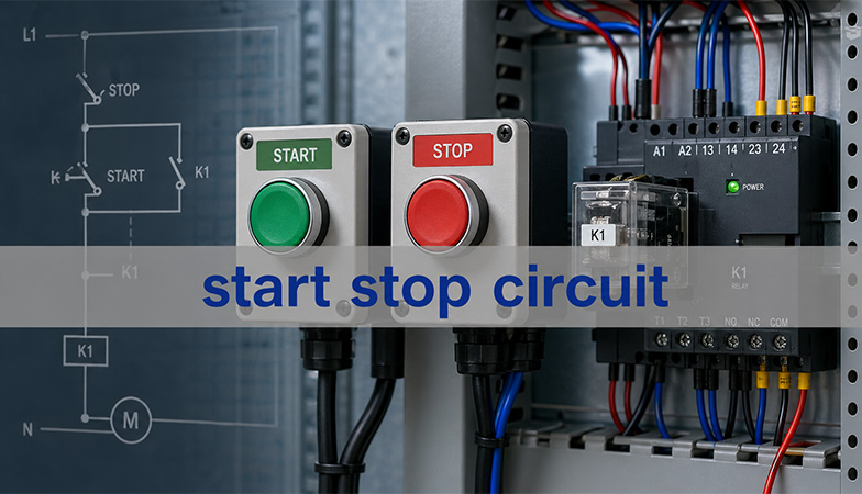
start stop circuit

How to Wire a Stop Start Circuit: 3-Wire Logic and PCB Checks
Thursday, August 6th, 2026

A start stop circuit uses a normally closed Stop path, a momentary normally open Start command, and an auxiliary holding contact to keep a relay or contactor energized after the Start button is released. Correct wiring makes Stop dominant: opening any series stop, overload, or permitted interlock removes coil power, while restoration of power does not restart the machine automatically.
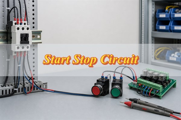
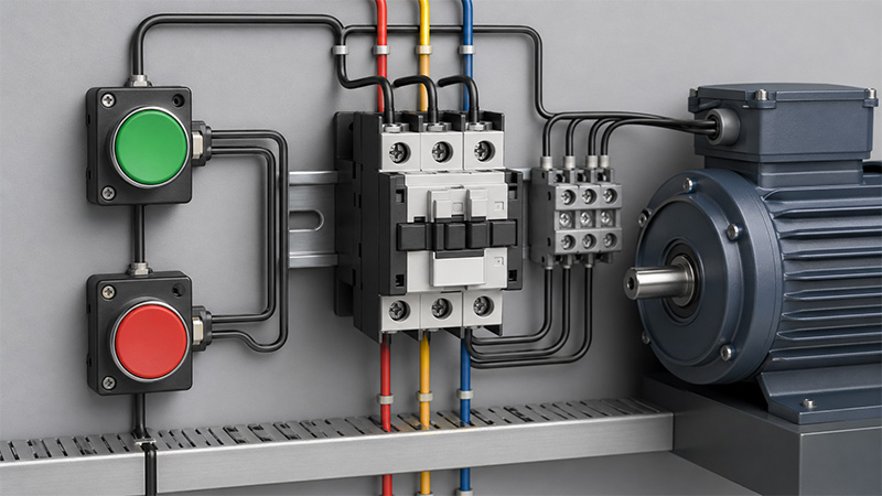
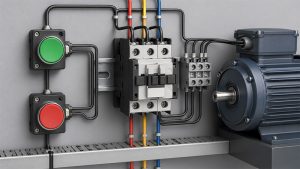
Start stop circuit wiring with contactor, pushbuttons, and PCB interface

How Does a Stop Start Circuit Work?

A three-wire stop-start circuit creates electrical memory with a holding contact. Pressing Start briefly energizes the contactor coil. A normally open auxiliary contact belonging to that contactor then closes in parallel with the Start button, so the coil remains energized after the button springs open.

Pressing Stop opens the series control path. The coil drops out, the main power contacts open, and the auxiliary holding contact returns open. A control-power interruption produces the same result. When power returns, the open holding contact prevents an unintended restart; an operator must press Start again. This self-holding behavior, described in motor-control training literature and confirmed by manufacturer wiring material, is the key distinction between three-wire control and a maintained two-wire command.

Which Components Create the Start, Hold, and Stop States?

Three contact functions create the basic states: NC Stop, NO Start, and NO auxiliary hold. The relay or contactor coil converts the logic into mechanical contact movement, while an overload contact and other permissives can interrupt the same series path.

Element Normal state Function Critical check
Stop pushbutton Normally closed Opens the coil circuit when pressed Confirm the NC terminals, not the lamp or NO block
Start pushbutton Normally open Provides the momentary pickup path Confirm it is paralleled only by the hold contact
Auxiliary contact Normally open Maintains coil current after Start is released Use a contact mechanically associated with the commanded device
Coil De-energized Operates the contactor or control relay Match AC/DC type and rated control voltage
Overload NC contact Closed when reset Drops the coil after an overload trip Keep it in the control path and verify manual/reset behavior

An electromechanical relay uses an energized coil to move its contacts. NO means open in the de-energized normal state; NC means closed in that state. Always read the device datasheet and terminal diagram because physical terminal placement is not standardized by appearance.

How Do You Read a Standard 3-Wire Stop Start Schematic?

Read the control rung from the supply toward the coil, following every series stop condition before the parallel start-and-hold branch. A typical path is control supply, fuse or control protection, NC Stop, NC overload, other NC permissives, the Start/hold branch, and the coil return.

  • Series logic: Any series NC element can remove coil power, so the circuit behaves like an AND chain of permissive conditions.
  • Parallel logic: The momentary Start contact and the NO auxiliary contact provide two alternative paths to the same coil node.
  • Device identity: The coil reference and its auxiliary contact reference must identify the same contactor or relay.
  • Normal condition: Schematics normally show devices de-energized, pushbuttons released, and overloads reset.

Do not confuse the control rung with the motor power circuit. The control circuit commands the contactor coil; the main contacts carry the motor current and require their own protection and conductor sizing.

For a point-by-point reading, assume the Stop and overload contacts are closed and the coil is de-energized. Control voltage should be present up to the open Start contact, but not at the coil input. While Start is pressed, both sides of Start and the coil input should reach the expected control potential. After pickup, the auxiliary contact should provide the same path. If its device reference does not match the coil reference, or it never changes state with the contactor, the circuit cannot provide trustworthy holding logic.

How Do You Wire a Stop Start Circuit Without Defeating Stop-Dominant Logic?

Wire every stop-producing device in series ahead of both the Start contact and the holding branch. Then wire the NO auxiliary contact directly across the NO Start contact. This topology prevents the hold contact from bypassing Stop, overload, or interlock functions.

  1. Isolate and verify: Lock out all relevant power sources and prove the circuit de-energized with an appropriate tester.
  2. Confirm ratings: Check the control supply, coil voltage and frequency, pushbutton contact ratings, auxiliary-contact identity, and terminal torque requirements.
  3. Build the stop chain: Route the protected control supply through the NC Stop and the required NC overload or permissive contacts.
  4. Add the start branch: Connect the NO Start contact from the end of the stop chain to the coil input node.
  5. Add the hold branch: Wire the associated NO auxiliary contact in parallel with Start, never around the stop chain.
  6. Complete the return: Connect the other coil terminal to the correct control return or neutral according to the equipment diagram.
  7. Inspect before power: Perform continuity, polarity, separation, torque, and point-to-point checks against the released schematic.

A common dangerous error is landing the holding contact upstream of Stop. That allows the energized auxiliary path to keep feeding the coil after Stop opens. Another error is using an unrelated relay contact as the hold path; the command state can then disagree with the actual contactor state.

Before connecting the load, verify three expected outcomes with the control circuit alone: Start must pick up and hold the coil, Stop must drop it regardless of the Start-button state, and removal and restoration of control power must leave it de-energized. Measure the voltage directly across the coil rather than assuming that one terminal measured to ground proves a complete circuit. A failed result should be traced node by node; do not move conductors by trial and error.

When Should You Use 2-Wire Instead of 3-Wire Control?

Use two-wire control when a maintained external device should command automatic operation; use three-wire control when deliberate manual restart is required. A thermostat, pressure switch, level switch, or PLC output may be a valid maintained command, but its restart behavior must match the machine risk assessment and control specification.

Decision point 2-wire control 3-wire control
Command device Maintained contact Momentary Start and Stop buttons
After control power returns May restart if the command remains closed Normally remains stopped until Start is pressed
Typical use Automatic process demand Operator-controlled machinery
Main design question Is automatic restart acceptable and controlled? Does every stop condition break the holding circuit?

Two-wire is not an inferior circuit; it serves a different operating intent. Where automatic restart could expose personnel or damage equipment, do not select the topology by convenience. Compare the operating sequence with these three-wire motor-control fundamentals, then apply the machine’s safety requirements and a documented risk assessment.

Where Should Overload, Interlock, and Emergency-Stop Functions Be Applied?

Overload and functional interlocks belong in the coil-control path, but an emergency-stop function requires a separately engineered safety architecture. A standard control PCB or ordinary relay must not be presented as a safety-rated emergency-stop system without the required design, components, validation, and applicable conformity work.

  • Overload contact: Place the overload relay’s NC auxiliary contact in series with the coil so a trip removes the run command.
  • Directional interlock: Use electrically and, where required, mechanically interlocked contactors to prevent simultaneous forward and reverse commands.
  • Process permissive: Put required limit, pressure, guard, or readiness conditions in the series logic only when their functional and safety roles are correctly defined.
  • Emergency stop: Design the stop category and safety function under the applicable machinery standard and risk assessment; do not route it solely through firmware.

Control-circuit protection, protective bonding, stop functions, and emergency switching are covered within the scope of IEC 60204-1 for machine electrical equipment. Applicability and required performance depend on the complete machine, not on the PCB alone.

An overload relay protects against sustained motor overcurrent; it is not a substitute for branch-circuit short-circuit protection. Its reset mode also changes restart risk: an automatically resetting overload can reclose its NC control contact while another maintained command is still present. The machine design must prevent that event from producing an unsafe restart. Likewise, a directional interlock should be checked for welded-contact and feedback faults, not only for simultaneous software commands. Where an emergency-stop function is required, use the safety components, redundant architecture, monitoring, reset behavior, and validation demanded by the risk assessment rather than assigning the function to an ordinary PCB relay.

How Should a Relay or Contactor Coil Be Driven from a PCB?

A PCB should drive a coil through a correctly rated interface stage, not directly from a logic pin. Calculate coil current from the actual datasheet, allow startup and temperature margin, verify the driver safe operating area, and choose suppression compatible with AC or DC coils.
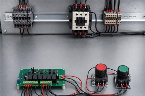
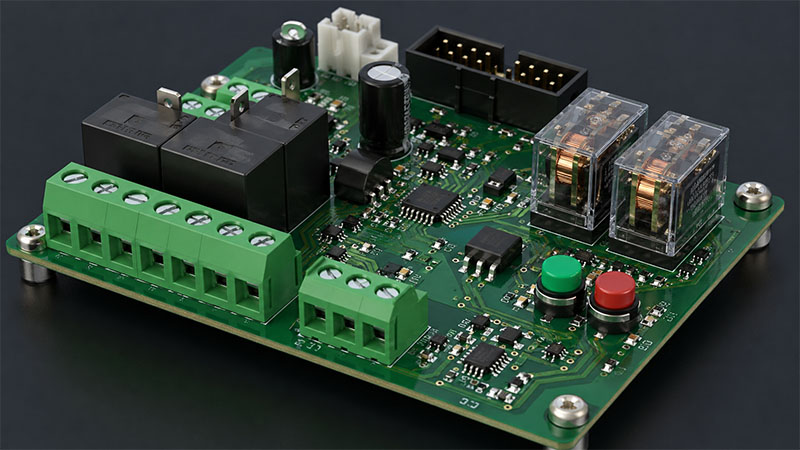
Relay coil driver PCB with terminals and isolation components
  • DC coil path: A low-side transistor or MOSFET is common; verify gate/base drive, current, voltage, thermal margin, and off-state leakage.
  • Flyback control: A diode limits DC-coil back EMF, while a Zener or TVS arrangement may release faster when the device permits it.
  • AC coil path: Use a suitable relay, triac, or isolated driver and the suppression method recommended for the coil and switching device.
  • Isolation boundary: Maintain the required separation between logic, control power, and any hazardous field circuit across copper, slots, components, and connectors.
  • Fault behavior: Check that processor reset, brownout, connector removal, and driver failure do not create an unintended run command.

Coil de-energization produces a voltage transient that can damage semiconductor drivers or cause malfunction. Manufacturer guidance also warns that suppression can lengthen relay release time. Verify the actual release behavior rather than assuming the strongest clamp is always best.

Start with the coil datasheet rather than the relay contact rating. For a DC coil, estimate steady current from the rated coil power and voltage using I = P / V, then confirm the manufacturer’s pickup voltage, hot-coil behavior, duty cycle, and tolerance. Select the transistor or MOSFET with margin above the maximum coil current and the unsuppressed transient voltage, and check dissipation during both steady operation and switching. Place the suppression path close to the coil or output connector so the transient loop does not travel through the logic return. During prototype testing, capture the driver drain or collector waveform and measure actual contactor release time with the final suppression network installed.

How Do You Size PCB Copper, Isolation, and Terminals for the Switching Load?

Size each current path from the real load, temperature rise, conductor geometry, environment, and terminal rating—not from relay contact current alone. In a start stop circuit, the coil path may carry modest current while PCB-mounted relay contacts can switch a much larger and more stressful load.

  • Copper capacity: Use the IPC-2152 methodology or validated thermal data with actual copper thickness, trace width, layer location, nearby copper, and permitted temperature rise.
  • Load category: Account for motor, solenoid, transformer, lamp, or capacitive inrush; a resistive current rating may not apply to an inductive load.
  • Clearance and creepage: Determine spacing from working voltage, insulation system, pollution degree, material group, overvoltage conditions, and the applicable product standard.
  • Terminal integrity: Rate the connector for conductor size, current, voltage, temperature, pitch, insertion method, and field torque.
  • Heat concentration: Review relay pins, fuse clips, narrow neck-downs, vias, copper pours, and terminals as one thermal path.

Do not publish a universal trace-width or spacing number without defined conditions. Put the assumptions in the design record and verify the hottest credible operating state on representative hardware.

The fabrication package should state copper weight, minimum finished conductor geometry, permitted temperature rise, isolation-class assumptions, material requirement, and any routed isolation slots. The assembly documentation should identify terminal part numbers, allowable wire range, stripping length, ferrule requirements, and tightening torque. On prototypes, test at the highest credible continuous current and ambient temperature after thermal stabilization. Measure the relay pins, terminal joints, fuse interfaces, narrow traces, and nearby temperature-sensitive components. Any unexplained hot spot, discoloration, unstable contact resistance, or temperature beyond the component and material limits requires redesign rather than a wider nominal trace alone.

What Causes a Stop Start Circuit to Fail to Start, Latch, or Stop?

Fault location follows the symptom: no start points to the series path, no latch points to the auxiliary branch, and no stop points to a bypass or welded device. Diagnose with power isolated first, then use energized measurements only under an approved safe procedure.

Symptom Likely cause Verification action
Will not start Open Stop, tripped overload, missing supply, wrong coil, broken wire Trace voltage or continuity through each series element
Starts only while held Wrong auxiliary terminals, failed auxiliary contact, open hold wire Confirm the associated NO contact closes and parallels Start
Will not stop Hold branch bypasses Stop, welded contact, unintended backfeed Isolate immediately and compare every node with the schematic
Chatters Low coil voltage, loose termination, unstable supply, wrong AC/DC coil Measure coil voltage during pickup and inspect connections
PCB resets on release Inadequate coil suppression, return-path coupling, weak supply decoupling Capture the transient and review grounding and suppression placement

Never defeat an overload or stop contact to “prove” the rest of the circuit. A temporary bypass can persist unnoticed, invalidate the stop logic, and expose the next operator to an unexpected start or failure to stop.

How Should a Stop Start Control PCB Be Verified Before Release?

Release requires schematic, bare-board, assembled-board, functional, abnormal-condition, and documentation checks. A single successful Start/Stop demonstration does not prove the PCB is safe, thermally adequate, or immune to realistic transients.
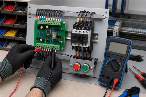
Start stop control PCB verification with multimeter probes
  1. Review the schematic: Confirm stop-dominant topology, coil ratings, contact identity, protection, isolation boundaries, and connector pinout.
  2. Inspect fabrication data: Check copper widths, clearances, slots, solder mask, drill sizes, annular rings, polarity marks, and test access.
  3. Inspect assembly: Verify component values, diode and optocoupler polarity, relay orientation, terminal seating, solder joints, and workmanship.
  4. Test unpowered nets: Measure for shorts, opens, isolation errors, and incorrect continuity through the released pushbutton states.
  5. Apply controlled power: Use current limiting where appropriate and verify standby, pickup, hold, stop, and power-loss behavior.
  6. Exercise faults: Open each stop/permissive input, trip the overload input, interrupt power, reset the processor, and disconnect field connectors one at a time.
  7. Measure stress: Record coil voltage/current, driver temperature, copper and terminal temperature rise, transient amplitude, and release time under defined loads.
  8. Check production tests: Define test points, fixtures, limits, traceability, firmware version controls, and pass/fail records suitable for repeat manufacture.

For fabrication and assembly review, provide the PCB manufacturer with controlled Gerber or ODB++ data, drill files, stackup and copper requirements, BOM, assembly drawings, polarity information, programming method, and the electrical test plan.

Define acceptance criteria before testing. With every stop or overload input opened, the coil must remain de-energized and a Start command must not override the open condition. After a control-power interruption, restoration must not create an automatic pickup in the three-wire mode. During driver testing, the measured transient must remain within the selected semiconductor and insulation limits, and the release time must satisfy the machine sequence. Thermal results should be compared with the documented ambient, load, stabilization time, and measurement uncertainty. Production test limits must be derived from these approved design results, not from one favorable prototype reading.

FAQs About Start Stop Circuit

Q1: Why is the Stop button normally closed?
A1: An NC Stop contact lets a broken wire or lost connection interrupt coil current. This improves fault visibility, although it does not by itself make the circuit safety-rated.

Q2: Can I use any auxiliary contact for the holding circuit?
A2: No. Use a NO auxiliary contact that changes state with the commanded relay or contactor. An unrelated contact can create false state memory.

Q3: Why does the contactor drop out when I release Start?
A3: The holding path is open, incorrectly wired, or associated with the wrong device. Check continuity across the NO auxiliary contact after pickup.

Q4: Will a three-wire circuit restart after a power failure?
A4: Normally no, because coil dropout opens the holding contact. A fresh Start command is required after control power returns.

Q5: Can a PLC replace the Start and Stop pushbuttons?
A5: A PLC can implement functional control, but restart behavior, hardwired stop requirements, output failure modes, and safety functions must be engineered. Do not substitute standard firmware for a required safety function.

Q6: Can a microcontroller pin drive a relay coil directly?
A6: Usually not. Coil current and turn-off voltage commonly exceed logic-pin capability. Use a rated driver and suppression network.

Q7: Does a flyback diode work on an AC coil?
A7: No. A simple diode across an AC coil would conduct on one half-cycle. Use the coil manufacturer’s approved AC suppression method, often an RC network or varistor.

Q8: What happens if Start and Stop are pressed together?
A8: In correctly wired stop-dominant logic, the open Stop path prevents coil pickup. Stop must override Start.

Q9: Can the PCB relay switch a motor directly?
A9: Only if the relay, PCB, terminals, protection, and load category are all rated for the motor’s starting and interruption duty. A contactor is often the appropriate power-switching device.

Q10: What files help a PCB supplier review this control board?
A10: Submit controlled fabrication data, stackup, copper requirements, BOM, assembly drawings, schematics, programming instructions, and test limits. Complete input data prevents avoidable assumptions.

Conclusion

A reliable stop-start design preserves stop dominance from the schematic through the finished PCB. Keep every stop condition ahead of the Start/hold branch, match the coil and driver, control inductive transients, size copper and terminals from real load conditions, and verify power-loss and fault behavior on representative hardware.

If you need manufacturing support for a stop-start control PCB, send your Gerber/ODB++, BOM, quantity, stackup, assembly details, programming method, and test requirements to sales@bestpcbs.com for engineering review and a quotation.

You may also like

What Is a Start Stop Circuit and How Does It Work?
Tuesday, April 28th, 2026

A start stop circuit is a control circuit used to start, hold, and stop electrical equipment safely. You will often see it in motor control panels, pumps, fans, conveyors, compressors, automation machines, and industrial control systems. The basic idea is simple: press the Start button to energize the system, and press the Stop button to shut it down.

However, behind this simple action is an important control logic. A good start and stop circuit must handle electrical safety, operator control, machine protection, relay or contactor operation, overload protection, and signal reliability. For PCB and PCBA manufacturing, this type of circuit is also closely related to control board design, relay output design, terminal block layout, isolation spacing, copper thickness, soldering quality, and functional testing.

In this article, we will explain how a start stop circuit works, how different wiring methods are used, what a start stop circuit diagram should include, and how PCB design affects long-term reliability.

start stop circuit

What Is a Start Stop Circuit?

A start stop circuit is an electrical control circuit that allows a machine or device to be started and stopped using separate push buttons. It is commonly used with relays, contactors, motor starters, PLC input modules, and industrial control PCBs.

In a traditional control panel, the circuit usually includes:

PartCommon Contact TypeFunction
Start buttonNormally open, NOStarts the circuit when pressed
Stop buttonNormally closed, NCOpens the circuit when pressed
Relay or contactor coilCoil loadEnergizes the control device
Auxiliary holding contactNormally open, NOKeeps the circuit running after Start is released
Overload relayNormally closed, NCStops the motor during overload
LoadMotor, pump, fan, machineThe equipment being controlled

The most important feature is the holding circuit, also called a latching circuit or seal-in circuit. This allows the machine to keep running after the operator releases the Start button.

For example, when an operator presses Start, the contactor coil receives power. Once the contactor pulls in, an auxiliary contact closes in parallel with the Start button. That closed contact keeps current flowing to the coil. The machine continues running until the Stop button is pressed or a safety device opens the circuit.

In PCB-based control products, the same logic may be created with:

  • Mechanical relays
  • MOSFETs
  • Optocouplers
  • MCU logic
  • PLC input and output terminals
  • Solid-state relay modules
  • Power control ICs

So, a start stop circuit can be built as a classic relay-control circuit or as a modern electronic control board.

How Does a Start Stop Circuit Work?

A start stop circuit works by controlling the power path to a relay coil, contactor coil, motor starter, or electronic switching device. The circuit has two basic operating states: stopped and running.

When the system is stopped, the Start button is open, so the control coil does not receive power. The machine remains off.

When the operator presses the Start button, the button closes for a short moment. Current flows through the Stop button, overload contact, Start button, and finally into the relay or contactor coil. The coil energizes and closes its main contacts. These main contacts allow power to reach the motor or load.

At the same time, an auxiliary contact closes. This auxiliary contact is wired in parallel with the Start button. Once it closes, it creates a second path for the control current. That is why the machine keeps running after the Start button is released.

When the operator presses the Stop button, the normally closed contact opens. This breaks the control circuit. The coil loses power, the contactor opens, and the motor stops.

The logic can be summarized like this:

ActionCircuit ResultMachine Status
Start button pressedCoil energizedMachine starts
Start button releasedHolding contact keeps coil energizedMachine keeps running
Stop button pressedControl circuit opensMachine stops
Overload tripsControl circuit opensMachine stops for protection
Power loss occursCoil drops outMachine stops

This design is widely used because it supports safe manual control. After a power failure, the machine usually does not restart automatically unless the circuit is intentionally designed for that behavior. This helps protect operators and equipment.

In industrial PCBA design, the same control logic must be handled carefully. The PCB may need input filtering, surge suppression, EMI protection, and isolation between control voltage and power switching areas.

What Are the Main Components in a Start and Stop Circuit?

A start and stop circuit may look simple on paper, but each component has a clear purpose. If one part is selected incorrectly, the whole control system may become unstable.

Start push button

The Start button is normally open. It only closes when pressed. In most machines, it is green or marked with “I”. Its job is to send a temporary start signal to the control circuit.

For PCB control boards, the Start signal may come from a panel button, membrane switch, metal dome keypad, touch input, or external terminal block. The PCB input circuit should be designed to prevent false triggering caused by noise, contact bounce, or long cable interference.

Stop push button

The Stop button is normally closed. It opens when pressed. This design is preferred because it is safer. If a wire breaks, a terminal loosens, or the button fails open, the machine stops instead of continuing to run.

This is an important point for industrial control boards. Safety-related stop signals are usually designed as active-open signals rather than active-close signals.

Relay or contactor

A relay is used for smaller loads or signal switching. A contactor is used for larger motors and higher current loads. In a motor start stop circuit, the contactor usually controls the three-phase power line, while the start stop control circuit operates at a lower voltage.

For PCBA manufacturing, relays need enough PCB spacing, suitable copper width, solid solder joints, and proper mechanical support. Large relays and terminal blocks may also need wave soldering or selective soldering after SMT assembly.

Auxiliary holding contact

The auxiliary contact is what makes the circuit stay on after Start is released. It creates the latching function. Without this contact, the machine would only run while the Start button is being held down.

On an electronic control PCB, this function can also be performed by MCU firmware, a flip-flop circuit, or relay feedback logic.

Overload protection

Motor circuits often include an overload relay. If the motor draws too much current for too long, the overload relay opens its normally closed contact and stops the control circuit. This protects the motor winding and the equipment.

PCB terminal blocks and connectors

In real industrial products, the start button, stop button, limit switch, motor starter, alarm output, and power supply often connect through terminal blocks. Good PCB layout should leave enough room for wiring, labels, screw access, creepage distance, and service inspection.

What Is the Difference Between a 2 Wire and 3 Wire Start Stop Circuit?

A common search question is the difference between a 2 wire start stop circuit and a 3 wire start stop circuit. These two designs behave differently.

TypeMain FeatureCommon Use
2 wire circuitUses a maintained contact deviceSimple remote control, float switch, thermostat
3 wire circuitUses momentary Start and Stop buttons with holding contactMotor starters, industrial machines, control panels

A 2 wire circuit usually uses one maintained switch. When the switch is closed, the circuit runs. When the switch is open, the circuit stops. This is simple, but it may restart automatically after a power failure if the switch remains closed.

A 3 wire start stop circuit uses three control paths: Stop, Start, and holding contact. The Start button is momentary. The Stop button is normally closed. The auxiliary contact holds the circuit after starting.

The 3 wire method is preferred for many motor control systems because it gives better operator control. After power is lost, the circuit drops out. The operator usually needs to press Start again after power returns. This reduces unexpected restart risk.

A simplified 3 wire logic looks like this:

Power → Stop NC → Overload NC → Start NO → Coil → Neutral
                         │
                         └── Auxiliary NO Holding Contact ──┘

When the coil energizes, the auxiliary contact closes. That contact bypasses the Start button and keeps the coil active.

For PCB and PCBA design, the 3 wire logic can be implemented with external wiring or integrated into the control board. If the board handles the latching logic electronically, engineers must define what happens during power loss, brownout, emergency stop, reset, and fault recovery.

This is where manufacturing experience matters. A PCB used in industrial control should not only match the schematic. It should also support stable field operation.

How Does a Motor Start Stop Circuit Control Industrial Equipment?

A motor start stop circuit controls the motor by energizing or de-energizing a motor contactor. The control circuit does not usually carry the full motor current. Instead, it controls the coil of the contactor. The contactor then switches the higher-power motor line.

For a 3 phase motor start stop circuit, the power section usually includes:

  • Three-phase input power
  • Main breaker or fuse
  • Magnetic contactor
  • Thermal overload relay
  • Three-phase motor

The control section usually includes:

  • Stop button
  • Start button
  • Contactor coil
  • Auxiliary holding contact
  • Overload relay auxiliary contact
  • Indicator lamp
  • Optional emergency stop
  • Optional PLC signal

This structure is used in many industrial applications:

ApplicationStart Stop Circuit Function
Conveyor systemStarts and stops material movement
Pump controllerControls water, oil, or chemical pumping
Ventilation fanControls airflow in equipment rooms
CompressorControls motor operation and protection
Packaging machineManages operator start and emergency stop logic
CNC auxiliary equipmentControls coolant pumps, fans, and fixtures

In modern equipment, the start stop function may be part of a PCBA control module. The board may include low-voltage control input, relay output, current sensing, LED indicators, and communication interfaces.

For this kind of board, PCB manufacturing quality is directly related to equipment reliability. Poor soldering, weak relay joints, narrow copper traces, or insufficient spacing can cause field failures. A control board may pass a simple power-on test, but it also needs to survive vibration, heat, repeated switching, and electrical noise.

That is why an experienced PCB and PCBA manufacturer should review the design before production. DFM checks, component verification, solder joint inspection, and functional testing can reduce many hidden risks before the boards are shipped.

What Should a Start Stop Circuit Diagram Include?

A good start stop circuit diagram should be easy to read, safe to wire, and clear enough for troubleshooting. It should not only show buttons and coils. It should show the real control logic and protection path.

A proper start stop circuit schematic or drawing should include:

Diagram ItemWhy It Matters
Power sourceShows control voltage, such as 24VDC, 110VAC, or 220VAC
Stop button contact typeConfirms NC safety logic
Start button contact typeConfirms NO start logic
Relay or contactor coil ratingPrevents wrong voltage selection
Auxiliary holding contactShows latching path
Overload relay contactShows motor protection path
Emergency stopShows safety stop function
Terminal numbersHelps assembly and field wiring
Wire labelsSupports maintenance and troubleshooting
Indicator lampsShows run, stop, or fault status
Grounding and isolation notesImproves safety and EMC performance

For PCB production, the schematic should also match the PCB layout and BOM. If a circuit uses relays, terminal blocks, optocouplers, fuses, MOVs, TVS diodes, or current sensors, these parts must be clearly specified.

One common problem in control PCB projects is that the schematic looks correct, but the layout is not robust enough. For example:

  • Relay contact spacing is too small.
  • High-voltage and low-voltage areas are too close.
  • Copper width is not enough for load current.
  • Terminal blocks are too close to tall components.
  • Silkscreen labels are unclear.
  • Surge protection is missing near field wiring.
  • Screw terminal solder pads do not have enough mechanical strength.

A professional PCBA manufacturer can help check these points before mass production. This is especially useful for industrial control boards, motor control boards, power control modules, and equipment interface boards.

How Does PCB Design Affect Start Stop Circuit Safety and Reliability?

PCB design has a strong influence on the safety and reliability of a start stop control board. Even when the circuit logic is correct, weak PCB design can cause heating, arcing, noise problems, relay failure, or unstable operation.

Copper thickness and trace width

If the PCB carries relay contact current or load current, the copper width must match the actual current. Higher current may require wider traces, heavier copper, or reinforced copper areas. For motor-related control boards, inrush current and switching current should also be considered.

Creepage and clearance distance

Start stop circuits may involve different voltage areas. For example, a board may have 24VDC logic and 220VAC relay output on the same PCB. The spacing between these areas must follow safety requirements. Slots, isolation gaps, and clear silkscreen marking can improve safety.

Relay and contactor interface design

Relay coils can create voltage spikes when switched off. A good PCB design may use flyback diodes, RC snubbers, MOVs, or TVS protection depending on whether the coil is DC or AC. This protects the control circuit and improves switching life.

Input signal stability

Start and Stop buttons may connect through long wires. Long wires can pick up electrical noise in industrial environments. Input filtering, pull-up or pull-down resistors, optocoupler isolation, and debounce design help the board read signals correctly.

Thermal management

Relays, power resistors, regulators, and protection devices generate heat. Component placement should allow heat to spread. In higher-power applications, copper pours, thermal vias, and proper enclosure airflow are useful.

Mechanical strength

Industrial control boards often use screw terminals, large relays, connectors, and manual wiring. These components receive mechanical stress during installation. Larger pads, through-hole plating quality, and proper soldering processes are important.

Manufacturing test points

A well-designed PCBA should include test points for power input, ground, relay coil signal, MCU reset, button input, and output status. This makes ICT, flying probe testing, and functional testing more efficient.

From a manufacturing viewpoint, the best design is not only electrically correct. It is also easy to assemble, inspect, test, and maintain.

What Testing Is Needed for Start Stop Circuit PCBA?

Testing is essential for start stop circuit boards because they are often used in equipment where stable operation matters. A small fault can stop a machine, damage a motor, or create downtime for the user.

For PCB and PCBA production, testing may include several stages.

Bare PCB inspection

Before assembly, the bare PCB should be checked for open circuits, short circuits, hole quality, solder mask quality, copper thickness, and surface finish. For control boards with high-voltage areas, spacing and routing should also be inspected.

SMT and DIP assembly inspection

After assembly, AOI can check component placement, polarity, solder bridges, missing parts, and wrong orientation. For through-hole relays and terminal blocks, visual inspection and solder joint inspection are also important.

Relay output testing

If the board includes relay outputs, each relay should be switched during testing. The test should confirm coil operation, contact continuity, LED indication, and output terminal behavior.

Button input testing

Start, Stop, Reset, Emergency Stop, limit switch, and sensor inputs should be tested under real signal conditions. For boards with optocoupler inputs, the input voltage range should be confirmed.

Functional testing

Functional testing checks whether the board behaves as expected. For example:

  • Apply control power.
  • Confirm the board remains in Stop state.
  • Trigger the Start input.
  • Confirm relay output turns on.
  • Release Start.
  • Confirm latch or run state remains active.
  • Trigger Stop input.
  • Confirm relay output turns off.
  • Simulate overload or fault input.
  • Confirm safe shutdown behavior.

Burn-in or aging test

Some industrial control boards benefit from burn-in testing. The board runs for a defined time under voltage and load conditions. This helps reveal early component or soldering problems.

Traceability check

For industrial, medical, automotive, and high-reliability projects, material traceability matters. Batch records, component sources, inspection data, and testing records help customers manage quality over the product lifecycle.

At EBest Circuit (Best Technology), we can support PCB fabrication, component sourcing, SMT assembly, DIP assembly, relay soldering, functional testing, and box-build related support for control board projects.

How to Choose a Reliable PCB and PCBA Manufacturer for Start Stop Circuits?

Choosing the right PCB and PCBA manufacturer is important when your start stop circuit is used in industrial control, motor control, automation equipment, or power switching products. These boards need more than basic assembly. They need engineering review and process control.

A reliable manufacturer should understand both PCB production and circuit application requirements.

Here are several points to check:

Selection PointWhy It Helps
PCB fabrication capabilitySupports proper copper thickness, spacing, drilling, and surface finish
PCBA assembly experienceHandles SMT, DIP, relays, connectors, and terminal blocks
Engineering DFM reviewFinds layout, soldering, spacing, and manufacturability issues early
Component sourcing supportReduces counterfeit risk and improves BOM stability
Functional testing abilityConfirms the circuit works before shipment
Traceability systemSupports batch control and quality records
Industrial control experienceHelps with relay boards, motor control boards, and equipment PCBA
Flexible productionSupports prototypes, small batches, and mass production

For start stop circuit boards, it is helpful to work with a manufacturer that can review practical details, such as:

  • Are the relay contacts rated correctly?
  • Is the control input protected from noise?
  • Is the spacing enough for the voltage?
  • Are terminal blocks easy to wire?
  • Can the board pass functional testing?
  • Are high-current traces wide enough?
  • Are through-hole components soldered reliably?
  • Can replacement components be sourced safely?

EBest Circuit (Best Technology) provides one-stop PCB and PCBA manufacturing services for industrial control boards, power control boards, relay boards, motor control PCBs, automation equipment boards, and custom electronic assemblies. Our team can support PCB fabrication, component sourcing, assembly, inspection, and testing, helping customers move from prototype to stable production with better confidence.

If your project includes a start stop circuit, motor control board, relay control module, or industrial PCBA, you can send your schematic, Gerber files, BOM, and testing requirements for engineering review. If any questions, pls feel free to contact us via sales@bestpcbs.com.

To sum up, a start stop circuit is one of the most widely used control circuits in electrical and industrial systems. It allows operators to start equipment, keep it running through a holding contact, and stop it safely when needed. Although the working principle is simple, the real design requires careful attention to wiring logic, contact ratings, overload protection, PCB layout, isolation spacing, and functional testing.

For PCB and PCBA projects, start stop circuits often appear in motor control boards, relay modules, automation controllers, power control boards, and industrial equipment interfaces. A reliable board should be easy to wire, stable in noisy environments, safe under voltage stress, and tested before delivery.

Working with an experienced PCB and PCBA manufacturer helps reduce design risk and improve production quality. From DFM review to component sourcing, assembly, inspection, and functional testing, every step contributes to a more dependable control board.

FAQs About Start Stop Circuit

What is a start stop circuit used for?
A start stop circuit is used to control equipment startup and shutdown. It is common in motors, pumps, fans, conveyors, machine tools, and industrial automation systems.

What is a 3 wire start stop circuit?
A 3 wire start stop circuit uses a Stop button, Start button, and auxiliary holding contact. It allows the machine to keep running after the Start button is released.

Why is the Stop button normally closed?
The Stop button is normally closed for safety. If the wire breaks or the button fails open, the control circuit opens and the machine stops.

What is the difference between a start stop circuit and a latching circuit?
A latching circuit keeps its output active after a temporary input signal. A start stop circuit often uses latching logic to keep a motor or relay running after the Start button is released.

Can a start stop circuit be built on a PCB?
Yes. A start stop function can be built on a PCB using relays, transistors, MOSFETs, optocouplers, MCU logic, or PLC interface circuits.

What should be checked before producing a start stop circuit PCBA?
The manufacturer should check schematic logic, PCB spacing, copper width, relay rating, terminal layout, component availability, soldering process, and functional test requirements.

What is a motor start stop circuit?
A motor start stop circuit controls a motor contactor. The control circuit energizes or de-energizes the contactor coil, and the contactor switches motor power.

Why does PCB quality matter in start stop circuits?
PCB quality affects electrical safety, solder joint strength, relay performance, signal stability, and long-term reliability in industrial environments.

You may also like