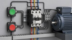
A start stop circuit uses a normally closed Stop path, a momentary normally open Start command, and an auxiliary holding contact to keep a relay or contactor energized after the Start button is released. Correct wiring makes Stop dominant: opening any series stop, overload, or permitted interlock removes coil power, while restoration of power does not restart the machine automatically.
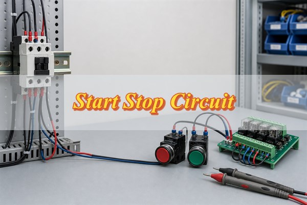
How Does a Stop Start Circuit Work?
A three-wire stop-start circuit creates electrical memory with a holding contact. Pressing Start briefly energizes the contactor coil. A normally open auxiliary contact belonging to that contactor then closes in parallel with the Start button, so the coil remains energized after the button springs open.
Pressing Stop opens the series control path. The coil drops out, the main power contacts open, and the auxiliary holding contact returns open. A control-power interruption produces the same result. When power returns, the open holding contact prevents an unintended restart; an operator must press Start again. This self-holding behavior, described in motor-control training literature and confirmed by manufacturer wiring material, is the key distinction between three-wire control and a maintained two-wire command.
Which Components Create the Start, Hold, and Stop States?
Three contact functions create the basic states: NC Stop, NO Start, and NO auxiliary hold. The relay or contactor coil converts the logic into mechanical contact movement, while an overload contact and other permissives can interrupt the same series path.
| Element | Normal state | Function | Critical check |
| Stop pushbutton | Normally closed | Opens the coil circuit when pressed | Confirm the NC terminals, not the lamp or NO block |
| Start pushbutton | Normally open | Provides the momentary pickup path | Confirm it is paralleled only by the hold contact |
| Auxiliary contact | Normally open | Maintains coil current after Start is released | Use a contact mechanically associated with the commanded device |
| Coil | De-energized | Operates the contactor or control relay | Match AC/DC type and rated control voltage |
| Overload NC contact | Closed when reset | Drops the coil after an overload trip | Keep it in the control path and verify manual/reset behavior |
An electromechanical relay uses an energized coil to move its contacts. NO means open in the de-energized normal state; NC means closed in that state. Always read the device datasheet and terminal diagram because physical terminal placement is not standardized by appearance.
How Do You Read a Standard 3-Wire Stop Start Schematic?
Read the control rung from the supply toward the coil, following every series stop condition before the parallel start-and-hold branch. A typical path is control supply, fuse or control protection, NC Stop, NC overload, other NC permissives, the Start/hold branch, and the coil return.
- Series logic: Any series NC element can remove coil power, so the circuit behaves like an AND chain of permissive conditions.
- Parallel logic: The momentary Start contact and the NO auxiliary contact provide two alternative paths to the same coil node.
- Device identity: The coil reference and its auxiliary contact reference must identify the same contactor or relay.
- Normal condition: Schematics normally show devices de-energized, pushbuttons released, and overloads reset.
Do not confuse the control rung with the motor power circuit. The control circuit commands the contactor coil; the main contacts carry the motor current and require their own protection and conductor sizing.
For a point-by-point reading, assume the Stop and overload contacts are closed and the coil is de-energized. Control voltage should be present up to the open Start contact, but not at the coil input. While Start is pressed, both sides of Start and the coil input should reach the expected control potential. After pickup, the auxiliary contact should provide the same path. If its device reference does not match the coil reference, or it never changes state with the contactor, the circuit cannot provide trustworthy holding logic.
How Do You Wire a Stop Start Circuit Without Defeating Stop-Dominant Logic?
Wire every stop-producing device in series ahead of both the Start contact and the holding branch. Then wire the NO auxiliary contact directly across the NO Start contact. This topology prevents the hold contact from bypassing Stop, overload, or interlock functions.
- Isolate and verify: Lock out all relevant power sources and prove the circuit de-energized with an appropriate tester.
- Confirm ratings: Check the control supply, coil voltage and frequency, pushbutton contact ratings, auxiliary-contact identity, and terminal torque requirements.
- Build the stop chain: Route the protected control supply through the NC Stop and the required NC overload or permissive contacts.
- Add the start branch: Connect the NO Start contact from the end of the stop chain to the coil input node.
- Add the hold branch: Wire the associated NO auxiliary contact in parallel with Start, never around the stop chain.
- Complete the return: Connect the other coil terminal to the correct control return or neutral according to the equipment diagram.
- Inspect before power: Perform continuity, polarity, separation, torque, and point-to-point checks against the released schematic.
A common dangerous error is landing the holding contact upstream of Stop. That allows the energized auxiliary path to keep feeding the coil after Stop opens. Another error is using an unrelated relay contact as the hold path; the command state can then disagree with the actual contactor state.
Before connecting the load, verify three expected outcomes with the control circuit alone: Start must pick up and hold the coil, Stop must drop it regardless of the Start-button state, and removal and restoration of control power must leave it de-energized. Measure the voltage directly across the coil rather than assuming that one terminal measured to ground proves a complete circuit. A failed result should be traced node by node; do not move conductors by trial and error.
When Should You Use 2-Wire Instead of 3-Wire Control?
Use two-wire control when a maintained external device should command automatic operation; use three-wire control when deliberate manual restart is required. A thermostat, pressure switch, level switch, or PLC output may be a valid maintained command, but its restart behavior must match the machine risk assessment and control specification.
| Decision point | 2-wire control | 3-wire control |
| Command device | Maintained contact | Momentary Start and Stop buttons |
| After control power returns | May restart if the command remains closed | Normally remains stopped until Start is pressed |
| Typical use | Automatic process demand | Operator-controlled machinery |
| Main design question | Is automatic restart acceptable and controlled? | Does every stop condition break the holding circuit? |
Two-wire is not an inferior circuit; it serves a different operating intent. Where automatic restart could expose personnel or damage equipment, do not select the topology by convenience. Compare the operating sequence with these three-wire motor-control fundamentals, then apply the machine’s safety requirements and a documented risk assessment.
Where Should Overload, Interlock, and Emergency-Stop Functions Be Applied?
Overload and functional interlocks belong in the coil-control path, but an emergency-stop function requires a separately engineered safety architecture. A standard control PCB or ordinary relay must not be presented as a safety-rated emergency-stop system without the required design, components, validation, and applicable conformity work.
- Overload contact: Place the overload relay’s NC auxiliary contact in series with the coil so a trip removes the run command.
- Directional interlock: Use electrically and, where required, mechanically interlocked contactors to prevent simultaneous forward and reverse commands.
- Process permissive: Put required limit, pressure, guard, or readiness conditions in the series logic only when their functional and safety roles are correctly defined.
- Emergency stop: Design the stop category and safety function under the applicable machinery standard and risk assessment; do not route it solely through firmware.
Control-circuit protection, protective bonding, stop functions, and emergency switching are covered within the scope of IEC 60204-1 for machine electrical equipment. Applicability and required performance depend on the complete machine, not on the PCB alone.
An overload relay protects against sustained motor overcurrent; it is not a substitute for branch-circuit short-circuit protection. Its reset mode also changes restart risk: an automatically resetting overload can reclose its NC control contact while another maintained command is still present. The machine design must prevent that event from producing an unsafe restart. Likewise, a directional interlock should be checked for welded-contact and feedback faults, not only for simultaneous software commands. Where an emergency-stop function is required, use the safety components, redundant architecture, monitoring, reset behavior, and validation demanded by the risk assessment rather than assigning the function to an ordinary PCB relay.
How Should a Relay or Contactor Coil Be Driven from a PCB?
A PCB should drive a coil through a correctly rated interface stage, not directly from a logic pin. Calculate coil current from the actual datasheet, allow startup and temperature margin, verify the driver safe operating area, and choose suppression compatible with AC or DC coils.
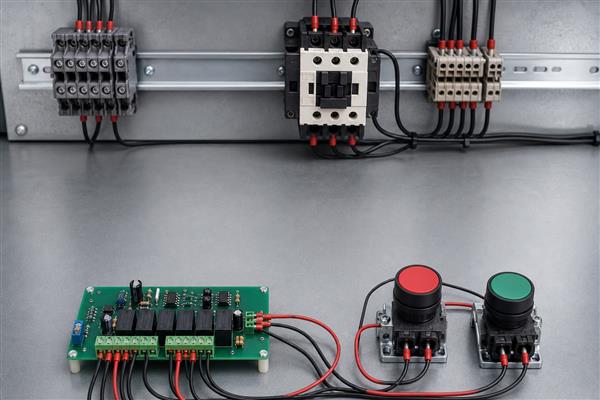
- DC coil path: A low-side transistor or MOSFET is common; verify gate/base drive, current, voltage, thermal margin, and off-state leakage.
- Flyback control: A diode limits DC-coil back EMF, while a Zener or TVS arrangement may release faster when the device permits it.
- AC coil path: Use a suitable relay, triac, or isolated driver and the suppression method recommended for the coil and switching device.
- Isolation boundary: Maintain the required separation between logic, control power, and any hazardous field circuit across copper, slots, components, and connectors.
- Fault behavior: Check that processor reset, brownout, connector removal, and driver failure do not create an unintended run command.
Coil de-energization produces a voltage transient that can damage semiconductor drivers or cause malfunction. Manufacturer guidance also warns that suppression can lengthen relay release time. Verify the actual release behavior rather than assuming the strongest clamp is always best.
Start with the coil datasheet rather than the relay contact rating. For a DC coil, estimate steady current from the rated coil power and voltage using I = P / V, then confirm the manufacturer’s pickup voltage, hot-coil behavior, duty cycle, and tolerance. Select the transistor or MOSFET with margin above the maximum coil current and the unsuppressed transient voltage, and check dissipation during both steady operation and switching. Place the suppression path close to the coil or output connector so the transient loop does not travel through the logic return. During prototype testing, capture the driver drain or collector waveform and measure actual contactor release time with the final suppression network installed.
How Do You Size PCB Copper, Isolation, and Terminals for the Switching Load?
Size each current path from the real load, temperature rise, conductor geometry, environment, and terminal rating—not from relay contact current alone. In a start stop circuit, the coil path may carry modest current while PCB-mounted relay contacts can switch a much larger and more stressful load.
- Copper capacity: Use the IPC-2152 methodology or validated thermal data with actual copper thickness, trace width, layer location, nearby copper, and permitted temperature rise.
- Load category: Account for motor, solenoid, transformer, lamp, or capacitive inrush; a resistive current rating may not apply to an inductive load.
- Clearance and creepage: Determine spacing from working voltage, insulation system, pollution degree, material group, overvoltage conditions, and the applicable product standard.
- Terminal integrity: Rate the connector for conductor size, current, voltage, temperature, pitch, insertion method, and field torque.
- Heat concentration: Review relay pins, fuse clips, narrow neck-downs, vias, copper pours, and terminals as one thermal path.
Do not publish a universal trace-width or spacing number without defined conditions. Put the assumptions in the design record and verify the hottest credible operating state on representative hardware.
The fabrication package should state copper weight, minimum finished conductor geometry, permitted temperature rise, isolation-class assumptions, material requirement, and any routed isolation slots. The assembly documentation should identify terminal part numbers, allowable wire range, stripping length, ferrule requirements, and tightening torque. On prototypes, test at the highest credible continuous current and ambient temperature after thermal stabilization. Measure the relay pins, terminal joints, fuse interfaces, narrow traces, and nearby temperature-sensitive components. Any unexplained hot spot, discoloration, unstable contact resistance, or temperature beyond the component and material limits requires redesign rather than a wider nominal trace alone.
What Causes a Stop Start Circuit to Fail to Start, Latch, or Stop?
Fault location follows the symptom: no start points to the series path, no latch points to the auxiliary branch, and no stop points to a bypass or welded device. Diagnose with power isolated first, then use energized measurements only under an approved safe procedure.
| Symptom | Likely cause | Verification action |
| Will not start | Open Stop, tripped overload, missing supply, wrong coil, broken wire | Trace voltage or continuity through each series element |
| Starts only while held | Wrong auxiliary terminals, failed auxiliary contact, open hold wire | Confirm the associated NO contact closes and parallels Start |
| Will not stop | Hold branch bypasses Stop, welded contact, unintended backfeed | Isolate immediately and compare every node with the schematic |
| Chatters | Low coil voltage, loose termination, unstable supply, wrong AC/DC coil | Measure coil voltage during pickup and inspect connections |
| PCB resets on release | Inadequate coil suppression, return-path coupling, weak supply decoupling | Capture the transient and review grounding and suppression placement |
Never defeat an overload or stop contact to “prove” the rest of the circuit. A temporary bypass can persist unnoticed, invalidate the stop logic, and expose the next operator to an unexpected start or failure to stop.
How Should a Stop Start Control PCB Be Verified Before Release?
Release requires schematic, bare-board, assembled-board, functional, abnormal-condition, and documentation checks. A single successful Start/Stop demonstration does not prove the PCB is safe, thermally adequate, or immune to realistic transients.
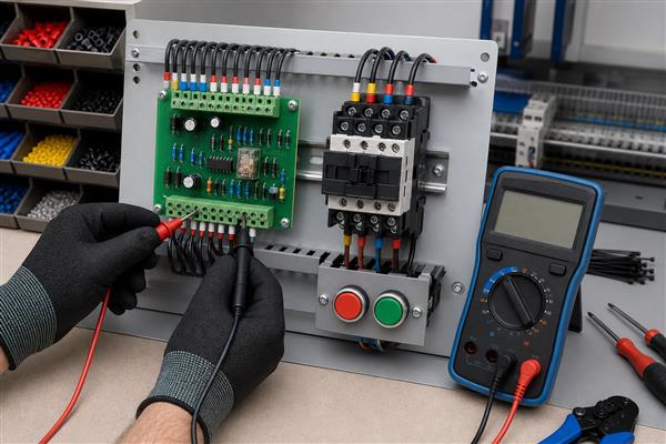
- Review the schematic: Confirm stop-dominant topology, coil ratings, contact identity, protection, isolation boundaries, and connector pinout.
- Inspect fabrication data: Check copper widths, clearances, slots, solder mask, drill sizes, annular rings, polarity marks, and test access.
- Inspect assembly: Verify component values, diode and optocoupler polarity, relay orientation, terminal seating, solder joints, and workmanship.
- Test unpowered nets: Measure for shorts, opens, isolation errors, and incorrect continuity through the released pushbutton states.
- Apply controlled power: Use current limiting where appropriate and verify standby, pickup, hold, stop, and power-loss behavior.
- Exercise faults: Open each stop/permissive input, trip the overload input, interrupt power, reset the processor, and disconnect field connectors one at a time.
- Measure stress: Record coil voltage/current, driver temperature, copper and terminal temperature rise, transient amplitude, and release time under defined loads.
- Check production tests: Define test points, fixtures, limits, traceability, firmware version controls, and pass/fail records suitable for repeat manufacture.
For fabrication and assembly review, provide the PCB manufacturer with controlled Gerber or ODB++ data, drill files, stackup and copper requirements, BOM, assembly drawings, polarity information, programming method, and the electrical test plan.
Define acceptance criteria before testing. With every stop or overload input opened, the coil must remain de-energized and a Start command must not override the open condition. After a control-power interruption, restoration must not create an automatic pickup in the three-wire mode. During driver testing, the measured transient must remain within the selected semiconductor and insulation limits, and the release time must satisfy the machine sequence. Thermal results should be compared with the documented ambient, load, stabilization time, and measurement uncertainty. Production test limits must be derived from these approved design results, not from one favorable prototype reading.
FAQs About Start Stop Circuit
Q1: Why is the Stop button normally closed?
A1: An NC Stop contact lets a broken wire or lost connection interrupt coil current. This improves fault visibility, although it does not by itself make the circuit safety-rated.
Q2: Can I use any auxiliary contact for the holding circuit?
A2: No. Use a NO auxiliary contact that changes state with the commanded relay or contactor. An unrelated contact can create false state memory.
Q3: Why does the contactor drop out when I release Start?
A3: The holding path is open, incorrectly wired, or associated with the wrong device. Check continuity across the NO auxiliary contact after pickup.
Q4: Will a three-wire circuit restart after a power failure?
A4: Normally no, because coil dropout opens the holding contact. A fresh Start command is required after control power returns.
Q5: Can a PLC replace the Start and Stop pushbuttons?
A5: A PLC can implement functional control, but restart behavior, hardwired stop requirements, output failure modes, and safety functions must be engineered. Do not substitute standard firmware for a required safety function.
Q6: Can a microcontroller pin drive a relay coil directly?
A6: Usually not. Coil current and turn-off voltage commonly exceed logic-pin capability. Use a rated driver and suppression network.
Q7: Does a flyback diode work on an AC coil?
A7: No. A simple diode across an AC coil would conduct on one half-cycle. Use the coil manufacturer’s approved AC suppression method, often an RC network or varistor.
Q8: What happens if Start and Stop are pressed together?
A8: In correctly wired stop-dominant logic, the open Stop path prevents coil pickup. Stop must override Start.
Q9: Can the PCB relay switch a motor directly?
A9: Only if the relay, PCB, terminals, protection, and load category are all rated for the motor’s starting and interruption duty. A contactor is often the appropriate power-switching device.
Q10: What files help a PCB supplier review this control board?
A10: Submit controlled fabrication data, stackup, copper requirements, BOM, assembly drawings, schematics, programming instructions, and test limits. Complete input data prevents avoidable assumptions.
Conclusion
A reliable stop-start design preserves stop dominance from the schematic through the finished PCB. Keep every stop condition ahead of the Start/hold branch, match the coil and driver, control inductive transients, size copper and terminals from real load conditions, and verify power-loss and fault behavior on representative hardware.
If you need manufacturing support for a stop-start control PCB, send your Gerber/ODB++, BOM, quantity, stackup, assembly details, programming method, and test requirements to sales@bestpcbs.com for engineering review and a quotation.