Start with two matched end terminations on a conventional linear CAN FD bus. With the bus safely de-energized and the applicable network isolated, about 60 Ω across CANH and CANL is a useful check for two nominal 120 Ω ends in parallel. It cannot tell you where those resistors are or whether a long stub is causing ringing. Check the physical ends next, then measure the differential and common-mode waveforms separately.
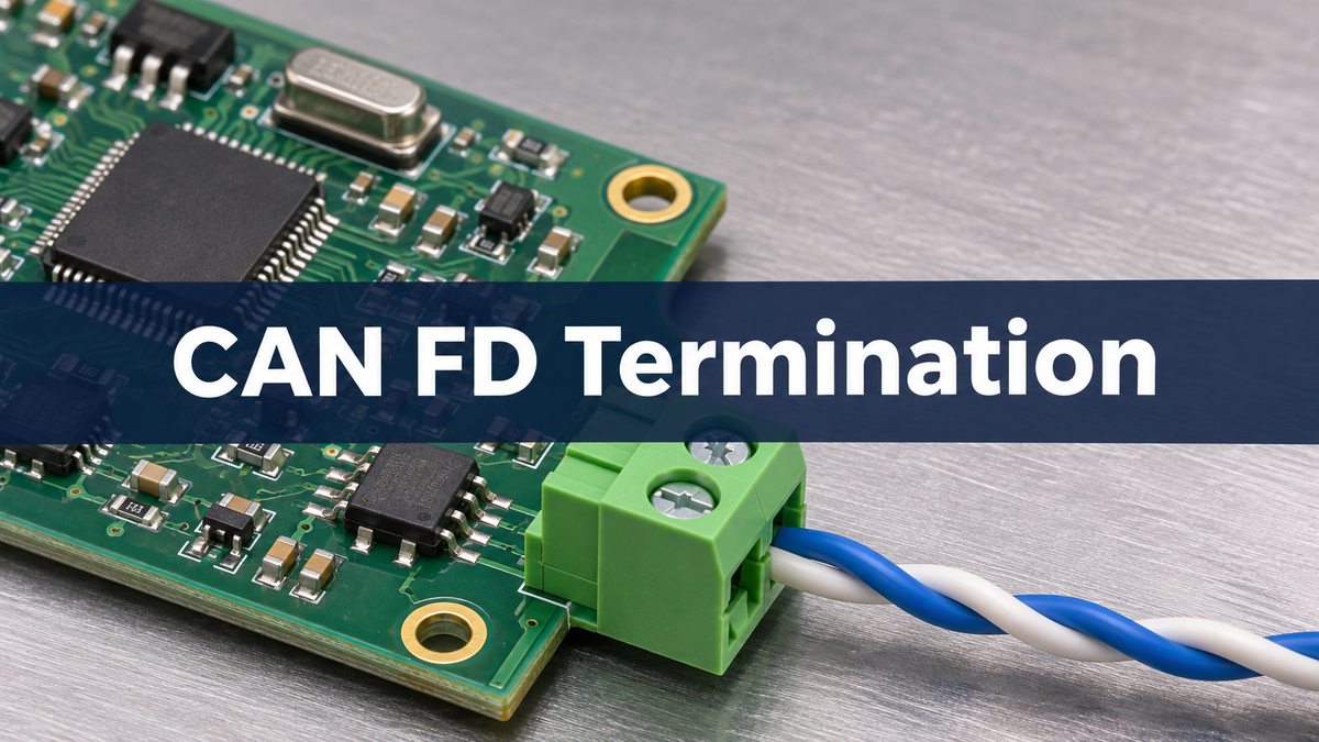
can fd termination
Termination matches the end of a transmission line to reduce reflected edges. The physical ends of the trunk are the ends that matter, not the two nodes with the lowest software addresses. Confirm the bus topology and cable impedance before applying the conventional two-end model. An engineered non-linear network needs its own analysis rather than extra resistors added by trial and error.
can bus termination resistor location
Walk the actual harness and mark both ends, every branch and any switchable termination. A termination at an intermediate node can still contribute the expected DC resistance while leaving a length of cable beyond it unterminated. In a hypothetical controller and sensor harness, a service node is plugged in midway and accidentally has termination enabled. If the far end is also missing its resistor, the meter can still show 60 Ω, yet the far end remains electrically open to an arriving edge.
can bus termination resistor value
For the conventional 120 Ω network, use a nominal 120 Ω differential termination at each physical end. In a split arrangement, two matched nominal 60 Ω resistors form one 120 Ω end. The midpoint capacitor adds a path for common-mode AC energy without adding a DC resistor across the pair.
| Parameter | What to verify |
| Nominal end resistance | 120 Ω for the conventional cable |
| Split pair | Two matched 60 Ω resistors per end |
| Midpoint capacitor | Value, rating and return for this design |
| Resistor power | Check fault voltage, duration and part rating |
can bus termination resistance
With power removed and the network in the intended measurement state, compare the reading with the expected parallel combination. Two 120 Ω resistors give 60 Ω, one gives 120 Ω and three give 40 Ω in the ideal calculation. Treat those as clues, not acceptance limits: tolerances, other DC paths, internal switches and the connected harness can change the reading. Segment the harness as permitted and identify each termination before concluding that a board needs rework.
can fd split termination
Use a single resistor when the end is correctly matched and the common-mode behavior meets requirements. Consider split termination when the end match is right but common-mode disturbance remains an issue. It adds parts and a return path to review. It does not move a termination to the right place or shorten a stub.
| Option | Use when | Verify |
| Single resistor | End match and emissions are acceptable | Value and physical location |
| Split pair plus capacitor | Common-mode improvement is needed | Matching, return and EMC result |
| Topology correction | There is an incorrect end or long stub | Reflection at the affected receiver |
can bus split termination capacitor value
Choose the starting value from the transceiver and system guidance. NXP’s FS2400 example lists 4.7 nF as a nominal option, not a universal requirement. In a simplified common-mode model, the two 60 Ω branches act in parallel, so the effective resistance is 30 Ω. Together with 4.7 nF that gives about 1.13 MHz for the ideal RC corner. Cable and return impedances, parasitics and other components change the real response. That number is not a CAN FD data-rate limit and cannot predict compliance.
can bus signal reflections
If errors cluster after edges or at the faster data phase, look for timing and topology clues before changing the capacitor. On the hypothetical service harness, restore termination at the physical far end and disable the misplaced branch termination. Repeat the same capture. If ringing persists at one branch, compare the branch connection and length against the approved network design. A changing common-mode signal alone is not proof of a differential reflection.
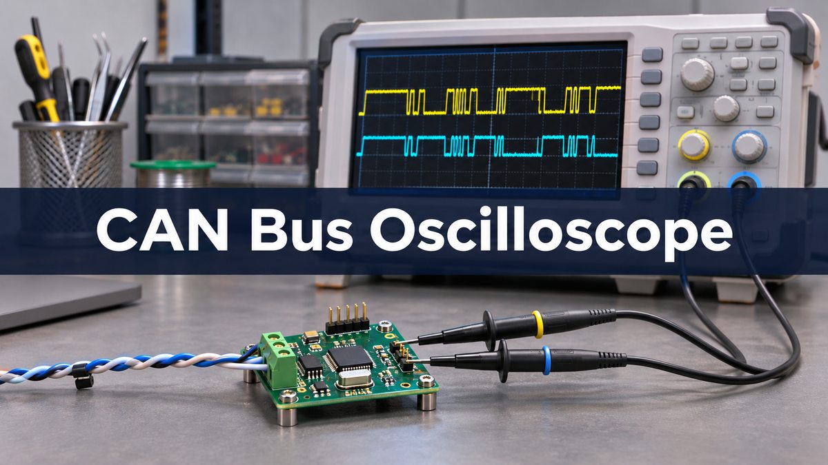
can bus oscilloscope waveform
Measure CANH minus CANL for differential behavior and, with a suitable referenced and matched setup, use their average to inspect common mode. Follow the instrument and equipment safety instructions and avoid grounding a floating bus through the probe. Compare the same receiver, harness, traffic and supply conditions before and after changes. Release only when the correct end map, resistance, waveform or timing limits, error behavior and any required system EMC tests meet the project plan.
FAQ
Why do I see 60 Ω but still get errors?
The meter cannot locate the resistors or see stubs, receiver timing or interference. Confirm the end map, then capture signals at the failing receiver.
Should every node include an enabled 120 Ω resistor?
No. In a conventional linear trunk, enable termination at the two physical ends. An optional resistor footprint on an intermediate node can remain unpopulated or disabled.
Does split termination change the nominal differential DC resistance?
Not when each end still sums to the specified end resistance and the midpoint capacitor has no DC conduction path under the measurement conditions.
Can I choose capacitor size by looking at the data rate?
Not alone. The midpoint network targets common-mode behavior. Start from the device guidance and verify it against the actual noise and immunity requirements.
Does unplugging a node always leave the resistance unchanged?
No. The unplugged module may contain an end resistor or active termination. Identify what was removed and re-evaluate the expected reading for that configuration.
Should I fit a common-mode choke before changing the layout?
Check the failure mechanism first. A choke may help a specific emissions or immunity issue, but it will not correct an unterminated cable end or an overly long stub.
Is a clean waveform at the transmitting node enough?
No. Check the receiver that sees errors and other electrically distinct points. A reflection that is mild at one location may be significant at another.
What if the conventional 60 Ω rule does not fit this network?
Use the network designer’s topology and expected measurement state. Switched termination, active networks and branches require interpretation beyond the simple parallel model.
Sources
NXP AN14183: CAN components example; TI: TCAN evaluation module termination options; TI: split termination and common-mode behavior.
Project Review
For a PCB fabrication discussion, send Best Technology the board stackup, connector region and proposed termination footprints at sales@bestpcbs.com. If the protocol itself is still being selected, see the CAN bus vs LIN bus guide.