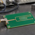
Choose signal integrity software by the decision you need to make, not by the most impressive 3D plot. A tool for exploring a driver and a transmission line, a tool for extracting a PCB interconnect, and a tool for checking an equalized serial channel solve different parts of the problem. The useful choice is the one that accepts your real models and geometry, predicts the receiver behaviour you care about, and leaves a result you can verify.
If you are moving from PCB layout into signal integrity, start by listing the interface, available device models, channel construction and required pass criteria. This guide explains how those inputs change the tool you need. The numerical examples are teaching calculations, not measured boards or benchmark results from the software products discussed.
What is signal integrity analysis?
Signal integrity analysis asks whether an electrical signal arrives at the receiver with enough voltage and timing margin to be interpreted correctly. It examines effects such as reflections, loss, crosstalk and timing variation. It does not normally simulate the complete logic or firmware running inside a complex IC.
Think of a digital output driving a trace into a receiver. The driver has a finite output impedance and edge shape. The route, vias, connector and package alter the waveform. The receiver then applies its input behaviour and timing requirements. A perfect square-wave source driving an ideal wire leaves out most of what you wanted to check.
Also separate clock rate from edge rate. A low-frequency control signal can still launch a fast transition. Whether transmission-line effects matter depends on the edge and interconnect delay, not only the frequency printed beside the clock. Use the actual component’s switching conditions and the intended layout rather than a universal “below this many MHz, simulation is unnecessary” rule.
For a simple reflection sanity check, consider an ideal 50 Ω single-ended line ending in 75 Ω. The load reflection coefficient is Γ = (75 − 50) / (75 + 50) = 0.20. That means a reflected voltage-wave amplitude equal to 20% of the incident wave at that ideal boundary. It is not a prediction of 20% receiver error or an interface pass/fail limit. Real source behaviour and repeated reflections change the observed waveform.
Signal integrity simulation tools: compare the jobs, not the logos
The first comparison should be between analysis functions. A circuit simulator evaluates a network and its sources. An electromagnetic extractor turns physical interconnect geometry into electrical behaviour. A channel-analysis workflow combines interconnect and endpoint models with the relevant stimulus and checks. A product suite may include several of these, but a particular licence may not.
| Tool class | Choose it for this decision; check this limitation |
| Circuit / transmission-line simulation | Explore termination, topology and driver/load interaction. You must supply appropriate device and interconnect models; a schematic does not automatically include PCB geometry. |
| PCB or package EM extraction | Determine how the physical route, vias, reference conductors and transitions affect the passive channel. Extraction alone does not establish the behaviour of the active transmitter and receiver. |
| Interface / channel analysis | Evaluate a specified serial or memory interface using supported models, operating modes and checks. Confirm the exact protocol revision, model functions and reporting supported by the proposed configuration. |
Named products are examples of workflows, not an accuracy ranking. Siemens describes HyperLynx SI for pre-layout exploration and post-layout verification. Its SerDes workflow distinguishes standards-based interconnect compliance from vendor-model IBIS-AMI simulation. Ask which of those jobs your proposed configuration includes.
Cadence’s Sigrity X platform describes separate analysis and modelling products, including Advanced SI with IBIS-AMI support. Ansys SIwave documentation describes frequency-dependent interconnect extraction and requires meaningful ports and net definitions. These capabilities can complement each other; do not treat a broad suite name as proof that every required solver and model interface is licensed.
HyperLynx vs Sigrity X vs SIwave: compare the proposed workflow
| Candidate workflow | Documented emphasis and the same trial question |
| HyperLynx SI / applicable SerDes configuration | Siemens documents pre/post-layout SI and standards-based or IBIS-AMI serial analysis. Ask the vendor to import your layout and endpoint models, apply your intended receiver analysis and identify which modules produce the final report. |
| Sigrity X / applicable Advanced SI configuration | Cadence describes PCB/package analysis and IBIS-AMI support within a modular platform. Run the same layout, endpoint models and receiver task; identify extraction, analysis and reporting entitlements rather than assuming the platform name includes them all. |
| SIwave with the required endpoint-analysis flow | Ansys documents PCB/package extraction and integration with other analysis tools. Run the same task and verify how extracted interconnects join the endpoint analysis, including model interfaces and any additional required product. |
These are alternative workflow proposals, not identical single-product licences. The first two explicitly describe the relevant interface-analysis functions; the SIwave extraction step needs its appropriate endpoint-analysis path. A proposal that omits that path is not a like-for-like substitute. Compare equivalent deliverables and included modules before comparing cost, and do not infer an accuracy winner from this feature review.
Choose circuit exploration when you need to compare terminations before routing. Choose geometry extraction when a via field or connector launch dominates the uncertainty. Choose the appropriate interface workflow when the decision is receiver margin under a defined mode. If the model chain crosses those boundaries, plan the handoff rather than forcing one tool to answer a question it has not been configured to solve.
IBIS vs SPICE model: what the endpoint needs
An IBIS model describes I/O-buffer behaviour; a SPICE model describes a circuit using supported device models and subcircuits. Neither name guarantees that the file represents your exact package, pin, drive setting or operating condition.
The IBIS Open Forum FAQ explains the behavioural approach: silicon vendors can provide I/O electrical data without disclosing the underlying transistor circuit. That is useful for digital-interconnect analysis. It does not turn a processor’s IBIS file into a model of its instruction execution, internal peripherals or software.
A model audit should identify the component revision, package, selected pin or model selector, voltage, drive strength and relevant corners. Check whether package parasitics are included and where the connection reference plane lies. Otherwise, adding a separate package network can count the same effect twice.
For SPICE, verify the dialect and supported model elements, not just the file extension. A model that runs in one simulator is not automatically portable to another. If the vendor provides only a model for a different buffer mode, do not quietly substitute it because the nominal voltage matches.
When a model is missing, decide what can still be learned. An ideal driver and line can demonstrate reflection mechanisms and compare assumed terminations. It cannot provide device-specific signoff. Label the assumption, retain the study for exploration, and obtain the supported model or another agreed validation route before approving the interface.
IBIS AMI model: when equalization changes the answer
IBIS-AMI adds algorithmic transmitter and receiver behaviour used in high-speed serial-link analysis. It matters when equalization and receiver processing change the decision. A passive S-parameter file describes the interconnect, not the complete equalized link.
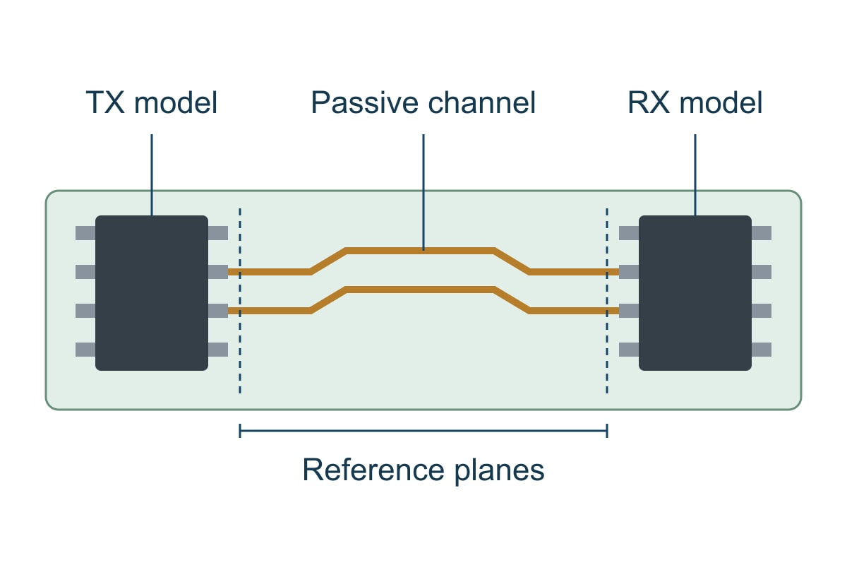
Before selecting a simulator for an AMI-based workflow, check the exact model package and its documented requirements: supported operating system and executable architecture, parameters, modes, initialization and waveform-processing options, and any tool-specific qualification notes. “Supports AMI” is a starting point, not evidence that the required model has been exercised successfully.
Next define the channel boundaries. Does the supplied network include the package? Are connector fixtures already removed? Which ports are transmitter-side and receiver-side? For a differential channel, verify conductor pairing and the conversion conventions. A plausible-looking eye is not enough if the port mapping is wrong.
Use the actual transmitter preset and receiver adaptation assumptions required by the study. Compare the intended configurations rather than picking whichever setting opens the eye most. Report the stimulus, analysis method, receiver settings and stated error-rate conditions when relevant. A statistical eye and an eye formed from a finite transient record are not interchangeable simply because both are drawn as eye diagrams.
Signal integrity simulation software: pre-layout vs post-layout
Pre-layout analysis explores a proposed electrical topology before the final route exists. Post-layout analysis evaluates the implemented interconnect. The first helps set design constraints; the second checks whether the actual routing and construction still meet them.
In a pre-layout study, vary one meaningful input at a time: route delay, load count, topology, termination or a supported drive setting. Keep a baseline so you can explain why a change helped. If the driver model and assumptions remain fixed, changing the termination can answer a useful question without pretending that the final board has been extracted.
Post-layout needs the correct board revision, layer order, dielectric and conductor dimensions, material models, net connectivity, reference conductors and discontinuities. Connector and package models must join that geometry at compatible reference planes. An extraction based on a guessed stackup can be internally consistent and still describe a board that will never be built.
| Input or parameter | Record it in a form that changes the decision |
| Data rate, coding and edge conditions | State bit rate or symbol rate explicitly, signal levels, rise/fall definition and supported driver mode. A clock frequency alone does not describe the launched transition. |
| Stackup and geometry | Use material designation, layer order, dimensions and the approved manufacturing interpretation. Retain frequency-dependent material data where the model requires it. |
| Channel and device models | Record model revisions, corner selections, port numbering, reference impedances and reference planes. Identify included packages, connectors and fixtures. |
| Acceptance criteria | Identify receiver thresholds/timing, the applicable interface requirement and analysis settings. A generic impedance target does not replace the interface’s acceptance conditions. |
Use manufacturing feedback before freezing the model, not after the analysis report is finished. A different dielectric thickness or copper geometry can change the channel you analysed. For the related fabrication task, the controlled-impedance PCB service describes stackup and trace-geometry review. That manufacturing review is not a substitute for system-level SI validation.
Signal integrity and power integrity tools: separate the checks
Signal integrity concerns the transmitted waveform and receiver decision. Power integrity concerns whether the supply network maintains the required voltage under load. They interact, but one result does not automatically validate the other.
A signal analysis with ideal supplies can be useful for isolating interconnect effects. It does not establish that simultaneous switching or supply noise is harmless. If those effects matter to the decision, use supported power-aware models and the necessary supply-network representation, or validate the missing contribution separately.
The required workflow changes by application. For a single-ended control interface, you may need receiver overshoot, ringing, monotonicity and timing relative to thresholds. For DDR, you need the relevant data/strobe or command/clock relationships across the specified configurations and corners. For an equalized SerDes channel, you need the applicable channel and receiver analysis. A tool’s general “SI/PI” label does not confirm all three tasks.
Before procurement, ask the vendor to run the task you will actually repeat: import your supported layout and models, apply your interface conditions, and produce the required report. If a model or licence feature is absent, record that gap. Do not replace the missing analysis with a separate PDN plot or a clean DRC report.
IPC manufacturing criteria, where contractually applicable, still matter to the fabricated board. They are not universal receiver eye-mask or bit-error requirements. Identify the actual interface and device documentation for electrical acceptance instead of attaching an unrelated IPC number to a software result.
Signal integrity software free: what you must build yourself
Free and open-source tools can support useful SI work, but “free” does not describe the completeness of the workflow. Check the model formats, extraction steps and validation tasks you will have to assemble yourself. Do not equate licence price with accuracy.
ngspice is an open-source circuit simulator whose manual includes transmission-line models. It can be useful for learning line behaviour and building a controlled circuit experiment. That does not establish automatic import of an arbitrary PCB database or direct compatibility with every vendor’s IBIS or AMI deliverable.
openEMS is an open electromagnetic solver using the finite-difference time-domain method, with scripting interfaces. It addresses a different part of the chain: physical electromagnetic behaviour. You must define geometry, materials, ports, mesh and boundaries correctly, and validate the extracted result. A field solver alone is not a complete DDR or serial-protocol signoff workflow.
A sensible low-budget starting exercise is a simple, well-defined transmission line whose expected behaviour you can calculate. Increase complexity only after the result survives basic checks and controlled changes. For commercial use, compare the time required to create and maintain that flow with the value of integrated import, automation, reporting and support in a paid configuration.
Request current licence terms and a representative trial from the vendor. Student, evaluation and commercial rights are not interchangeable. This guide does not quote prices or promise that a feature remains free; those conditions must be checked for the actual version and use.
Signal integrity simulation tutorial: qualify one real channel
Before buying a tool, qualify it against one representative channel and one clear decision. The deliverable is not “a simulation completed.” It is a reproducible result tied to the correct board, models, conditions and acceptance requirement.
- Freeze the inputs. Identify the layout revision, stackup, transmitter/receiver models and channel boundaries. Record what is omitted.
- Check the simple limit first. Use a known ideal case to catch units, connection and model-selection mistakes. The 50 Ω / 75 Ω example above should give a load reflection coefficient of 0.20 in that ideal setup.
- Import the representative channel. Check nets, conductor pairing and ports before interpreting plots. Confirm that included packages and fixtures are not added a second time.
- Apply the intended interface conditions. Select the supported device modes, corners and receiver assumptions. Save those settings with the result.
- Change one relevant variable. Compare the baseline with a justified change, such as a termination or supported drive setting. Explain the mechanism rather than just reporting a better-looking plot.
- Validate the evidence. Compare with an independent calculation, a trusted reference case or a suitable measurement with aligned reference planes and operating conditions. A match at one condition does not prove every corner.
For a numerical teaching example, assume a 5 Gb/s NRZ link, with one bit per symbol. Its unit interval is UI = 1 / (5 × 10⁹) = 200 ps. A hypothetical 20 ps timing allocation consumes 10% of one UI. That arithmetic helps interpret a timing budget; it does not prove that a 20 ps budget is appropriate or that any channel passes.
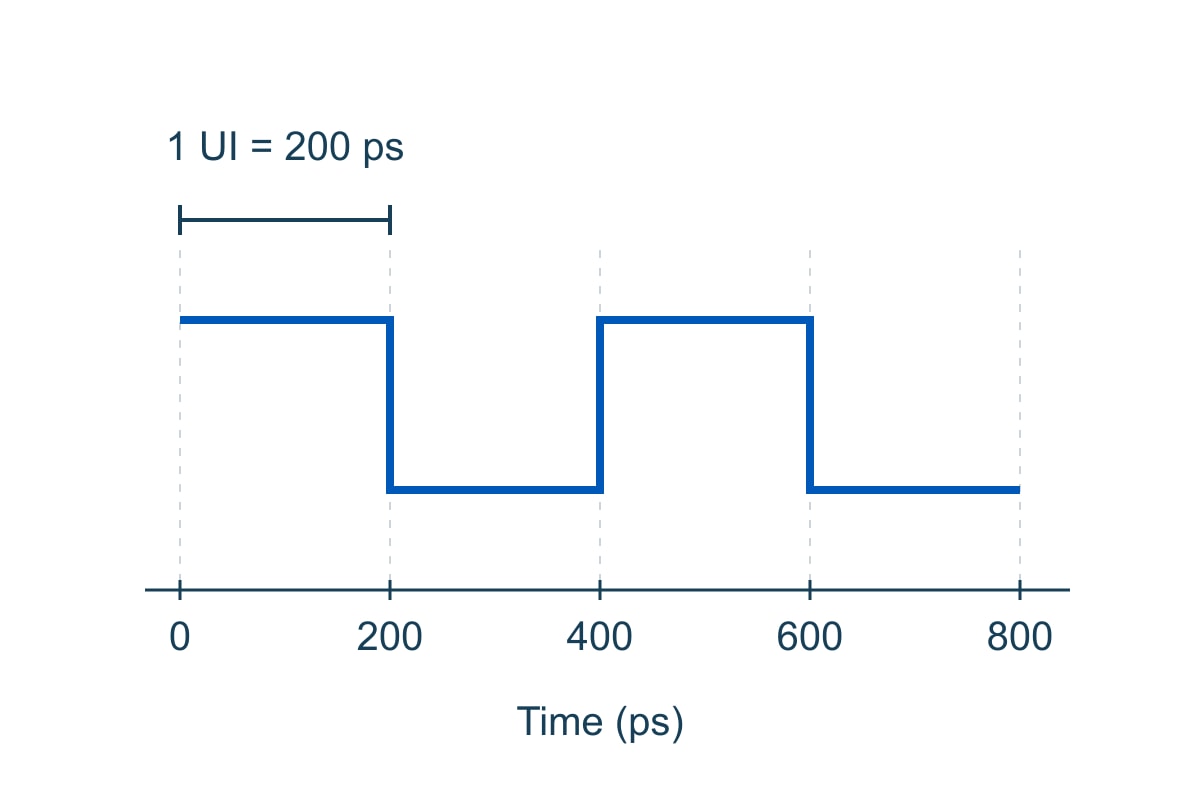
Alternating 1s and 0s in this example repeat every 400 ps, giving a 2.5 GHz fundamental. That is not the channel’s required maximum modelling frequency: transition shape and the analysis accuracy requirement determine the necessary bandwidth. For PAM4, bit rate and symbol rate are different, so do not reuse the NRZ bit-rate formula without identifying what rate is specified.
| Trial worksheet | Worked entry and approval question |
| Task and rate | Hypothetical 5 Gb/s NRZ channel; UI 200 ps. Can the tool apply the actual endpoint configuration and required receiver analysis? |
| Available evidence | Board revision, stackup, channel network and endpoint model package. Are the reference planes, package inclusion and port map consistent? |
| Timing allocation | Assumed 20 ps allocation = 10% UI. What approved requirement defines this allocation, and does the report use the same definition? |
| Missing receiver model | Hold device-specific signoff. The passive channel can still be studied, but an eye generated with a guessed receiver does not close the missing evidence. |
| Reproduction test | Reopen the saved setup and reproduce the key result. Retain tool version, model revisions, settings, report and the comparison evidence. |
Use the same worksheet for your own design: replace every hypothetical input, attach the applicable acceptance requirement and record the unresolved gap. If the report omits the board revision, receiver assumptions or model boundaries, it is not enough to support that decision. Agree on what must be rerun rather than approving a screenshot.
Signal Integrity Software FAQs
1. Can PCB layout software tell me whether the whole board works?
Not from layout and DRC alone. Layout rules, circuit behaviour, SI, PI, firmware and functional validation cover different questions. Check the exact analysis integrated into the selected software rather than assuming the layout editor includes all of them.
2. Can I replace a missing digital IC model with an ideal source?
For a clearly labelled exploratory study, yes. For device-specific approval, no: an ideal source lacks the actual buffer behaviour and may omit package and receiver effects. Record the model gap and obtain the appropriate evidence.
3. Does a successful model import prove compatibility?
No. Run the model’s documented reference case and check the required functions, modes and parameters. A parser accepting a file is weaker evidence than a verified result using the intended configuration.
4. Is the tool with a 3D solver always the best choice?
No. Use the representation that captures the decision’s important effects with validated assumptions. A simple topology experiment may be sufficient for early termination exploration; a complex transition may require detailed extraction.
5. Can I compare two tools using their default eye plots?
Only after aligning the models, channel boundaries, stimulus, corners, receiver processing and measurement definitions. Otherwise, a difference may come from setup rather than the numerical solver.
6. How many bits must a transient eye contain?
There is no universal number that proves a particular error rate. Record the pattern and length, the effects modelled and the analysis method. Use the interface’s required method; a short waveform does not directly demonstrate extremely rare events.
7. Is an impedance calculator an SI simulator?
It can estimate a useful interconnect parameter under stated assumptions. It does not by itself combine the driver, receiver, complete channel and operating conditions into a receiver-level validation.
8. What should a software vendor demonstrate before I commit?
Your representative import, actual model package, required analysis and a reproducible report under the proposed licence. List any unsupported model function or manual conversion. Do not approve a workflow based only on an unrelated demonstration board.
Technical references
Product capabilities are based on the linked Siemens, Cadence and Ansys documentation checked for this guide, not a comparative benchmark. Model interpretation uses the IBIS Open Forum; the open-source descriptions use the ngspice and openEMS projects. Version, module and licence details must still be confirmed for the intended installation. The engineer’s question about choosing SI tools informed the reader task, not an accuracy ranking.
Custom High-Speed PCBs with Stackup Engineering Support
Turn your analysed channel into a clearly specified manufacturing job. EBest Circuit supports custom controlled-impedance PCBs with stackup and trace-geometry review, plus PCB and PCBA manufacturing support. That helps your team align the intended interconnect with the construction submitted for production and keep fabrication and assembly requirements in one project. It is not a promise to supply SI software or certify a simulated interface.
Send the fabrication data, proposed stackup, material requirements, impedance table, quantity and requested schedule. Include the BOM and placement data if you need assembly. Email sales@bestpcbs.com to request a manufacturing review and project-specific quotation. Flag which geometry and material assumptions must be preserved so they can be reviewed before production is approved.
You may also like

Tags: high-speed pcb, IBIS Models, PCB Simulation, Signal Integrity