PCB manufacturing PCB manufacturing
Home > Blog

SMD resistor

Thin Film vs Thick Film Resistor: Which Fits Your Circuit?
Sunday, October 4th, 2026

Thin film vs thick film resistor selection affects how accurately a circuit performs after temperature, load, and operating time begin to change. Two chip resistors may have the same nominal value and package but differ in temperature coefficient, noise, long-term drift, pulse behavior, and price. Choosing the appropriate technology helps the assembled board reproduce the performance established during validation.

The correct choice depends on the circuit requirement and the exact component datasheet; neither technology is universally better. EBest Circuit can source customer-approved resistors, manufacture the PCB, assemble the PCBA, inspect the soldering, and perform agreed tests. This guide explains the differences that matter before a part number or alternative is released for production.
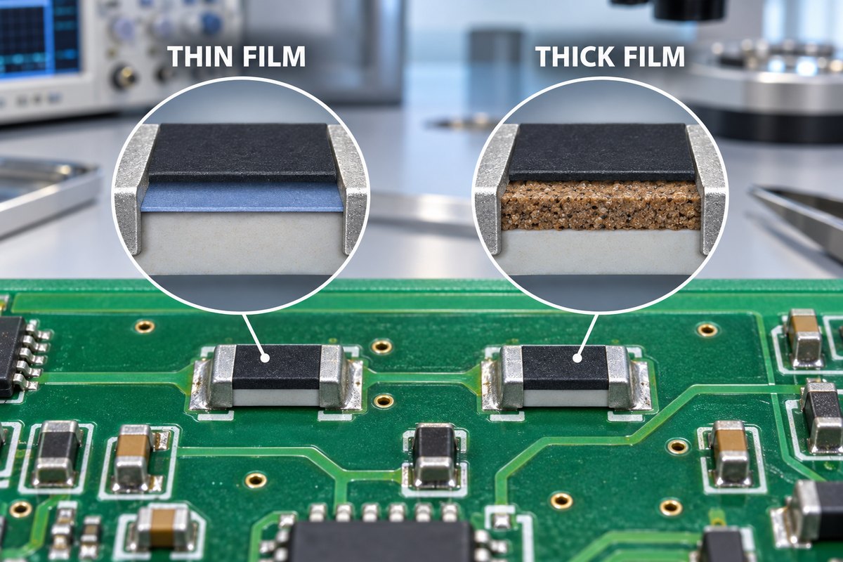
thin film vs thick film resistor

What Is the Difference Between Thick and Thin Film Resistors?

The main difference is the resistive element. A thin film resistor normally uses a uniform metallic layer deposited onto a ceramic substrate. A thick film resistor normally uses a resistive paste that is printed onto the substrate and fired at high temperature. These different structures produce different performance ranges.

Selection factor Thin film resistor Thick film resistor
Typical advantage Precision and stability Cost and availability
TCR and excess noise Often lower Often higher
Long-term drift Often lower in comparable precision series More dependent on formulation and load
Pulse performance Depends on the selected series Pulse-resistant series are widely available
Common role Precision analog and measurement General-purpose circuit positions

The practical difference: thin film is often selected when resistor error directly affects circuit accuracy, while thick film is often selected when its specified performance already meets the requirement at a more practical cost.

These are common tendencies, not guaranteed limits. Precision thick film products and specialized thin film products can cross those boundaries. The final comparison must use the exact resistance value, package, operating conditions, and manufacturer datasheets.

Why Does Resistor Construction Change Its Performance?
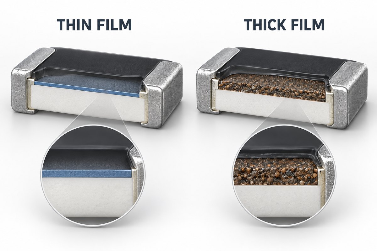
thin film vs thick film resistor

Construction changes performance because current passes through a different material structure. The uniformity of that structure influences how resistance responds to temperature, voltage, electrical load, and time.

  • Thin film: A metallic alloy is deposited in a thin, relatively uniform layer. Controlled patterning and trimming can provide low TCR, low excess noise, and stable resistance, which is useful when small changes affect circuit accuracy.
  • Thick film: A resistive paste containing conductive material and glass is printed and fired. The process is economical and supports a broad selection of resistance values and packages. Manufacturers can also optimize particular series for pulse, voltage, sulfur resistance, or automotive use.

Construction does not determine performance by itself. Package size, resistance value, trimming geometry, electrodes, protective coating, ambient temperature, PCB heat dissipation, and electrical load also affect the result. The words “thin film” or “thick film” cannot replace a complete datasheet review.

When Should You Choose a Thin Film Resistor?

Choose a thin film resistor when small resistance changes would directly affect measurement accuracy, gain, reference stability, or low-level signal quality. Its customer benefit is not merely a tighter value at room temperature; it is better control of the circuit error as temperature and operating time change.

Choose thin film when the circuit depends on:

  • low temperature drift across the specified operating range;
  • low excess noise in a sensitive analog or measurement path;
  • stable absolute resistance or matched resistor ratios over time.

Typical positions include precision dividers, feedback networks, sensor interfaces, instrumentation amplifiers, reference paths, and matched resistor circuits. In these applications, TCR, load-life drift, humidity performance, and resistance tracking may be as important as initial tolerance.

Do not choose it from tolerance alone. A 0.1% tolerance does not prove that the resistor will remain within the required error across the complete operating range. Approval should be based on the circuit’s total error budget. If lower TCR, lower noise, or greater stability does not improve the application, a thin film part may add cost without improving the finished product.

When Should You Choose a Thick Film Resistor?

Choose a thick film resistor when its specified tolerance, TCR, noise, and drift already satisfy the circuit and the project benefits from lower cost or broader availability. The decision normally falls into two practical situations:

  • General-purpose circuit positions: Thick film is often suitable for pull-ups, pull-downs, LED current limiting, biasing, discharge paths, and other functions that do not determine precision performance.
  • Pulse, surge, or higher-voltage positions: A thick film part may be appropriate only when the selected series is specifically rated for the real load. The “thick film” label alone does not prove pulse or voltage capability.

For a pulse-loaded position, compare the actual peak voltage, pulse duration, energy, repetition rate, ambient temperature, and allowed resistance change with the manufacturer’s pulse-load data. Average power may hide a damaging short-duration event.

Package size is not proof of pulse survival. A larger resistor can provide more margin, but package size and film technology do not replace the pulse curve, derating rules, and limits of the exact part number.

Can Thin Film and Thick Film Resistors Be BOM Alternatives?

Thin film and thick film resistors are not automatic BOM alternatives, even when their resistance, tolerance, package, and nominal power rating match. A substitution is acceptable only when every specification that matters to the circuit and product qualification remains within the approved limits.

What must remain equivalent What to compare
Accuracy over operating conditions Tolerance, TCR, resistance tracking and long-term drift
Electrical load capability Continuous power, working voltage, overload and pulse ratings
Circuit behavior Excess noise, voltage coefficient and relevant frequency behavior
Production requirements Package, terminals, qualification, lifecycle and traceability

A resistance check proves nominal value—not equivalence. A room-temperature measurement cannot confirm the same temperature drift, noise, pulse survival, or long-term stability. Physical fit on the same PCB land pattern proves only mechanical compatibility.

Use the released MPN or a customer-approved alternative. When purchasing proposes a replacement because of cost or availability, the electrical differences should be reviewed and authorized before the new part enters production. This prevents an invisible sourcing change from altering a validated circuit.

Does Resistor Type Change the PCB Assembly Process?
thin film vs thick film resistor

Resistor type alone usually does not change the PCB assembly process. The important distinction is between soldering requirements and material-control requirements.

  • Assembly process: Reflow conditions and solder-joint formation are influenced more directly by package dimensions, terminal finish, pad geometry, stencil aperture, solder paste, placement accuracy, and the component manufacturer’s process limits.
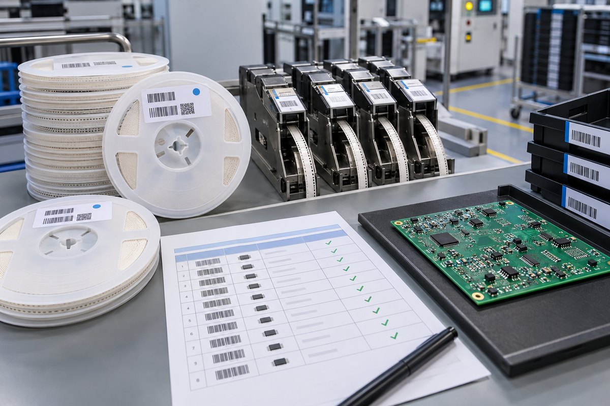
  • Material control: A thin film resistor and a thick film resistor may look identical after placement, especially when the package has no readable marking. AOI can verify presence, alignment, and visible solder condition, but it normally cannot identify the internal resistive technology.

To preserve the customer’s approved component choice, production records should connect the BOM position with the manufacturer part number, reel label, purchasing record, feeder setup, and required lot traceability. Any proposed alternative should receive documented approval before use.

Agreed functional testing can confirm defined board behavior, but it cannot automatically prove every component characteristic. Test limits and conditions must represent the customer’s validated requirement.

EBest Circuit can manufacture and assemble customer-designed PCBs with approved thin film or thick film resistors from prototypes through repeat production. By connecting the released BOM with component sourcing, SMT setup, inspection, and agreed testing, we help customers keep the validated component decision consistent between batches. For a quotation or BOM and DFM review, send your Gerber files, BOM, assembly drawings, and test requirements to sales@bestpcbs.com.

FAQs About Thin Film vs Thick Film Resistor

Is a thin film resistor the same as a metal film resistor?

Not always. Thin film describes how a resistive layer is formed, while metal film is a broader material and construction term that may include different component formats. Use the exact manufacturer description and datasheet instead of treating the names as interchangeable.

Can thin film and thick film chip resistors use the same PCB footprint?

Yes, when their package dimensions and terminal geometry are compatible. Sharing a footprint does not make their electrical performance equivalent or authorize a BOM substitution.

Can soldering change the resistance of a precision resistor?

Soldering heat can cause a specified resistance shift. Pad design, thermal mass, reflow profile, rework temperature, and the number of heat cycles can influence the stress applied during assembly. The component datasheet should define the permitted change.

Can resistance measurement identify whether a resistor is thin film or thick film?

No. A resistance measurement verifies the measured value under the test conditions, but it does not identify the internal technology or prove TCR, noise, pulse capability, and long-term drift. Identification should rely on the approved part number and material traceability.

Thin film vs thick film resistor selection should protect the finished circuit rather than merely satisfy one resistance value in the BOM. If your project needs controlled component sourcing, PCB fabrication, SMT assembly, inspection, and agreed testing, contact EBest Circuit at sales@bestpcbs.com with the released production files and approved component requirements.
You may also like

SMD Resistor Dimensions: The Ultimate Guide to Packages, Footprints & Selection
Wednesday, December 3rd, 2025

If you’ve ever stared at a PCB prototype covered in misplaced components or wasted weeks reworking a design because the resistors didn’t fit, you know the frustration. smd resistor dimensions aren’t just arbitrary numbers—they’re the backbone of reliable electronics design. Understanding smd resistor dimensions ensures your components integrate seamlessly with PCBs, perform as expected under load, and avoid costly manufacturing delays. Whether you’re a hobbyist building a DIY project or an engineer designing industrial equipment, getting the dimensions right is non-negotiable. Let’s break down everything you need to know to stop guessing and start choosing with confidence.

SMD Resistor Dimensions: The Ultimate Guide to Packages, Footprints & Selection https://www.bestpcbs.com/blog/2025/12/smd-resistor-dimensions/

2. What Are SMD Resistors? A Quick Primer for Beginners

SMD resistors (Surface Mount Device resistors) are the compact, lead-free workhorses of modern electronics. Unlike traditional through-hole resistors that require drilled holes in PCBs, SMD resistors mount directly onto the board’s surface, saving valuable space and enabling faster assembly. Their key advantages over through-hole alternatives include a 50% smaller footprint, better high-frequency performance, and compatibility with automated pick-and-place machines—critical for mass production. But here’s the catch: their small size means smd resistor dimensions directly dictate what they can do. A tiny 0201 resistor might fit in a smartwatch, but it can’t handle the power demands of an industrial power supply. Size isn’t just about space—it’s about functionality.

SMD Resistor Dimensions: The Ultimate Guide to Packages, Footprints & Selection https://www.bestpcbs.com/blog/2025/12/smd-resistor-dimensions/

3. Understanding SMD Resistor Dimension Codes (Imperial vs. Metric)

One of the most common headaches with SMD resistors is decoding their size codes—and it’s easy to see why. Two global systems dominate: imperial (used primarily in North America and Europe) and metric (favored in Asia). The 4-digit codes look similar, but they mean entirely different things. Let’s demystify them:

  • Imperial codes: The first two digits = length (in 1/100 of an inch), the last two = width (in 1/100 of an inch). For example, 0402 = 0.04” (length) x 0.02” (width), and 1206 = 0.12” x 0.06”.
  • Metric codes: The first two digits = length (in millimeters), the last two = width (in millimeters). So 1608 = 1.6mm x 0.8mm, and 3216 = 3.2mm x 1.6mm.

The biggest mistake? Confusing imperial 0603 with metric 0603. Imperial 0603 = 1.6mm x 0.8mm (metric 1608), while metric 0603 = 0.6mm x 0.3mm (imperial 0201)—a difference that can ruin your entire PCB. Pro tip: Always confirm the code system with your supplier, and keep a conversion chart handy (multiply inches by 25.4 to get millimeters, or pide millimeters by 25.4 for inches).

4. smd resistor package dimensions

Common SMD Resistor Package Sizes (Detailed Specs + Comparative Chart)

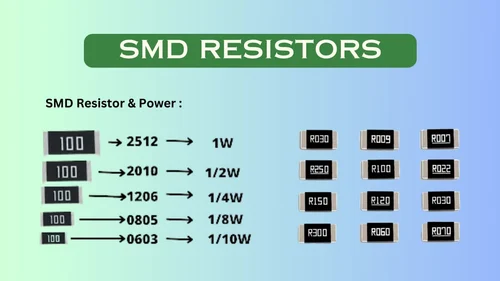
When people talk about smd resistor dimensions, they’re usually referring to package size—the physical length, width, and height of the component. Here are the most widely used packages, with specs that matter:

Imperial CodeMetric CodeDimensions (mm)Dimensions (inch)Rated Power (W)Height (mm)
020106030.6 x 0.30.024 x 0.0120.050.25
040210051.0 x 0.50.039 x 0.0200.0630.35
060316081.6 x 0.80.063 x 0.0310.100.45
080520122.0 x 1.20.079 x 0.0470.1250.55
120632163.2 x 1.60.126 x 0.0630.250.75
251264326.4 x 3.20.252 x 0.1261.001.20

Notice how power rating scales with size? A 2512 package can handle 1W of power, while a tiny 0201 maxes out at 0.05W. This is because larger packages have more surface area for heat dissipation—critical for high-power applications.

SMD Resistor Dimensions: The Ultimate Guide to Packages, Footprints & Selection https://www.bestpcbs.com/blog/2025/12/smd-resistor-dimensions/

How Package Dimensions Impact Thermal Dissipation & Assembly

Thermal management is where smd resistor dimensions really shine (or fail). Smaller packages like 0201 and 0402 are great for compact devices (think smartphones or wearables), but they struggle with heat. If you push a 0402 resistor beyond its 0.063W limit, it’ll overheat, drift in resistance, or even burn out. Larger packages like 1206 and 2512 spread heat more effectively, making them ideal for power supplies or industrial controls.

Assembly is another factor. Ultra-small packages (0201) require precision automated equipment—forget hand-soldering them unless you have steady hands and a microscope. For hobbyists or small-batch projects, 0805 and 1206 are the sweet spot: easy to solder manually while still saving space.

SMD Resistor Dimensions: The Ultimate Guide to Packages, Footprints & Selection https://www.bestpcbs.com/blog/2025/12/smd-resistor-dimensions/

5. smd resistor footprint dimensions

What Is an SMD Resistor Footprint? (Land Pattern Basics)

If smd resistor dimensions are about the component itself, footprint dimensions are about how it connects to the PCB. A footprint (or land pattern) is the layout of copper pads on the PCB where the resistor solders. Think of it as the resistor’s “home”—if the home is too big or too small, the resistor won’t sit right.

Footprints follow global standards set by IPC (Association Connecting Electronics Industries) and JEDEC (Joint Electron Device Engineering Council). These standards ensure compatibility across manufacturers—so a 0805 resistor from Texas Instruments fits the same footprint as one from Yageo. Ignoring these standards leads to problems: pads too small cause poor solder joints, while pads too large result in solder bridging (short circuits) or the resistor shifting during assembly.

Standard Footprint Dimensions by Package

Here are the IPC-recommended footprint dimensions for the most common SMD resistor packages (pad length x width x gap between pads):

  • 0603 (1608): Pad length = 1.2mm, pad width = 0.8mm, gap = 0.4mm
  • 0805 (2012): Pad length = 1.5mm, pad width = 1.0mm, gap = 0.5mm
  • 1206 (3216): Pad length = 2.0mm, pad width = 1.4mm, gap = 0.6mm
  • 2512 (6432): Pad length = 3.0mm, pad width = 2.5mm, gap = 0.8mm

These are starting points—adjustments may be needed for high-temperature applications or flexible PCBs. Always cross-check with your resistor’s datasheet and your PCB design software (Altium, KiCad) for manufacturer-specific recommendations.

6. Key Factors to Consider When Choosing SMD Resistor Dimensions

PCB Space Constraints (High-Density vs. Industrial Designs)

The first question to ask: How much space do you have? High-density designs (like wearables or IoT sensors) demand tiny packages (0201, 0402) to fit all components. Industrial equipment or power supplies have more room, so you can opt for larger packages (1206, 2512) that offer better performance and easier assembly. Don’t force a small package if space allows—bigger often means more reliable.

Power Requirements & Performance Tradeoffs

Power rating is non-negotiable. Calculate the maximum power your resistor will handle (using Ohm’s Law: P = VÂČ/R or P = IÂČR) and choose a package that exceeds that by 20-30% for safety. For example, if your circuit requires 0.1W, a 0603 (0.1W) works, but a 0805 (0.125W) gives extra headroom for heat spikes.

Assembly Method (Automated vs. Hand Soldering)

Automated pick-and-place machines handle tiny packages (0201, 0402) with ease, but hand soldering them is frustrating (and error-prone). If you’re building prototypes or small batches, stick to 0805 or 1206. For mass production, automated assembly opens up smaller package options.

Global Supply Chain Compatibility

Not all packages are equally available worldwide. Ultra-small packages (0201) may be harder to source in some regions, or more expensive. Stick to common packages (0402, 0603, 0805, 1206) for easier procurement and consistent quality across suppliers.

7. Common Mistakes in SMD Resistor Dimension Selection (And Fixes)

Even experienced engineers mess up smd resistor dimensions—here are the top mistakes and how to avoid them:

  • Mistake 1: Ignoring thermal limits. Solution: Always derate resistors (use a higher power rating than needed) and check datasheets for temperature vs. power curves.
  • Mistake 2: Confusing imperial and metric codes. Solution: Label your BOM (Bill of Materials) with both codes (e.g., 0603 / 1608) and confirm with suppliers.
  • Mistake 3: Choosing a package too small for hand soldering. Solution: For manual assembly, avoid anything smaller than 0805 unless you have specialized tools.
  • Mistake 4: Mismatched footprints. Solution: Use PCB design software’s built-in footprint libraries (Altium, KiCad) or download from the resistor manufacturer’s website.

8. SMD Resistor Dimensions for Specific Applications

Consumer Electronics (Smartphones, Wearables)

Space is at a premium here—so packages like 0201 and 0402 are standard. These tiny SMD resistors fit in tight spaces while handling low power (0.05-0.1W). Examples: A smartphone’s display driver might use 0402 resistors, while a fitness tracker uses 0201s.

Industrial Equipment (Power Supplies, Controls)

Industrial gear needs durability and heat resistance. Packages like 1206 and 2512 are common, as they handle higher power (0.25-1W) and dissipate heat better. A factory’s motor controller, for example, might use 2512 resistors to handle power spikes.

Automotive & Medical Devices

These industries demand reliability in harsh conditions (extreme temperatures, vibration). Packages like 0805, 1206, and 1210 are preferred—they’re robust enough to withstand automotive underhood temperatures or medical device sterilization cycles. Automotive infotainment systems often use 0805 resistors, while medical monitors use 1206s.

9. How to Measure SMD Resistor Dimensions Accurately

If you’re unsure about a resistor’s size (or suspect a counterfeit), measuring it is simple—you just need the right tools:

  1. Gather tools: Digital calipers (with 0.01mm precision) and a magnifying glass or microscope (for tiny packages).
  2. Measure length: Place the resistor on a flat surface and measure the longest side (avoid pressing too hard—SMD resistors are fragile).
  3. Measure width: Measure the shorter side perpendicular to the length.
  4. Measure height: Measure from the flat surface to the top of the resistor (this affects PCB clearance).
  5. Verify: Cross-check your measurements with the code on the resistor (e.g., if you measure 1.6mm x 0.8mm, it should be a 0603 / 1608 package).

Pro tip: Counterfeit resistors often have incorrect dimensions—if your 0805 resistor measures 1.8mm x 0.9mm instead of 2.0mm x 1.2mm, it’s likely fake.

10. SMD Resistor Dimensions vs. Through-Hole Resistors: Comparison

How do smd resistor dimensions stack up against traditional through-hole resistors? Let’s break it down:

  • Size: SMD resistors are 50-70% smaller in footprint. A 1206 SMD resistor (3.2mm x 1.6mm) is tiny compared to a through-hole 1/4W resistor (6.3mm x 3.2mm).
  • Height: SMD resistors sit 0.25-1.2mm above the PCB, while through-hole resistors stand 8-10mm tall—critical for low-profile devices.
  • Performance: SMD resistors have better high-frequency performance (less parasitic inductance) and faster heat dissipation (direct contact with the PCB).
  • Assembly: Through-hole resistors are easier to hand-solder but slower to assemble in bulk. SMD resistors require automation for mass production but save time overall.

When to choose SMD: Most modern electronics (consumer, industrial, automotive) benefit from SMD’s small size and performance. When to choose through-hole: Prototyping (easy to solder), high-power applications (some through-hole resistors handle 5W+), or legacy designs.

11. FAQ: Common Questions About SMD Resistor Dimensions

  • Q1: What do the 4 digits in SMD resistor codes represent?A1: For imperial codes (e.g., 0402), the first two digits = length (1/100 inch), last two = width (1/100 inch). For metric codes (e.g., 1608), first two = length (mm), last two = width (mm).
  • Q2: Can I replace a 0603 resistor with a 0805 if space allows?A2: Yes—if the power rating is equal or higher. A 0805 (0.125W) can replace a 0603 (0.1W) as long as your PCB has space for the larger footprint.
  • Q3: Why do different manufacturers label the same package with slightly different dimensions?A3: Manufacturers have minor tolerances (±0.1mm for length/width). Stick to IPC/JEDEC standards, and the differences won’t affect compatibility.
  • Q4: Which SMD resistor size is easiest for hand soldering?A4: 0805 is the sweet spot—large enough to handle with tweezers and solder with a standard iron, but small enough to save space.
  • Q5: Are there standard footprint dimensions for all SMD resistor packages?
    A5: Yes—IPC/JEDEC sets global standards. Use your PCB design software’s library or download from manufacturers like Yageo or Vishay.
  • Q6: Does temperature affect SMD resistor dimensions?
    A6: Negligibly. SMD resistors are made of ceramic and metal films, which have low thermal expansion. Temperatures up to 150°C won’t change their dimensions enough to cause issues.
  • Q7: What’s the smallest mass-produced SMD resistor size?
    A7: 01005 (imperial) or 0402 (metric) = 0.4mm x 0.2mm. It’s used in ultra-compact devices like smartwatches but requires specialized assembly.
  • Q8: How do I calculate the right footprint for my PCB?
    A8: Use IPC-7351 (the industry standard) or your resistor’s datasheet. Most PCB design software (Altium, KiCad) has built-in calculators to generate footprints based on package size.

12. Final Thoughts: Mastering SMD Resistor Dimensions for Better Designs

smd resistor dimensions might seem intimidating at first, but they’re just a matter of understanding tradeoffs—space vs. power, size vs. assembly ease. The key takeaway? Never choose a package based on size alone—align it with your application’s power needs, assembly method, and PCB constraints. By mastering code translation, footprint standards, and application-specific sizing, you’ll eliminate rework, reduce costs, and build more reliable electronics.

Remember: A SMD resistor is only as good as its fit—get the dimensions right, and everything else falls into place. For more details, check out IPC-7351 (the definitive guide to footprint design) or reach out to your resistor supplier for custom recommendations. Whether you’re building a prototype or scaling to mass production, this guide will keep your designs on track.

You may also like