Thin film vs thick film resistor selection affects how accurately a circuit performs after temperature, load, and operating time begin to change. Two chip resistors may have the same nominal value and package but differ in temperature coefficient, noise, long-term drift, pulse behavior, and price. Choosing the appropriate technology helps the assembled board reproduce the performance established during validation.
The correct choice depends on the circuit requirement and the exact component datasheet; neither technology is universally better. EBest Circuit can source customer-approved resistors, manufacture the PCB, assemble the PCBA, inspect the soldering, and perform agreed tests. This guide explains the differences that matter before a part number or alternative is released for production.
What Is the Difference Between Thick and Thin Film Resistors?
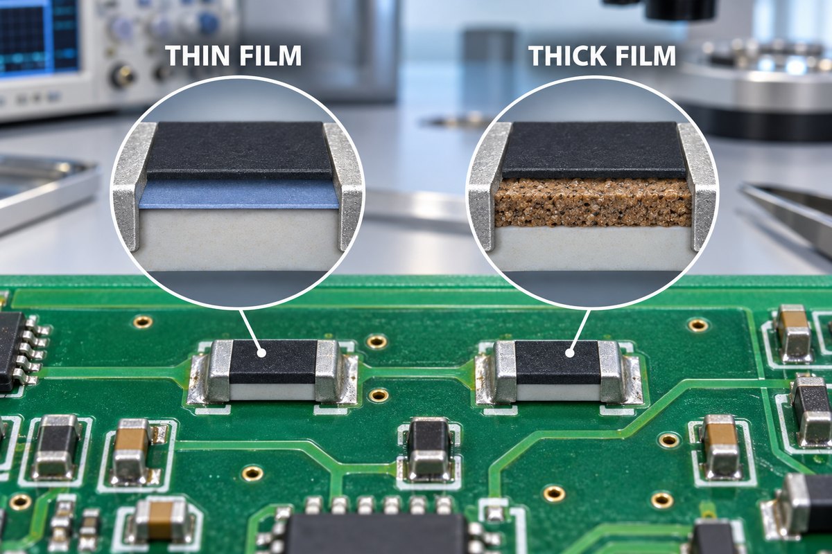
The main difference is the resistive element. A thin film resistor normally uses a uniform metallic layer deposited onto a ceramic substrate. A thick film resistor normally uses a resistive paste that is printed onto the substrate and fired at high temperature. These different structures produce different performance ranges.
| Selection factor | Thin film resistor | Thick film resistor |
|---|---|---|
| Typical advantage | Precision and stability | Cost and availability |
| TCR and excess noise | Often lower | Often higher |
| Long-term drift | Often lower in comparable precision series | More dependent on formulation and load |
| Pulse performance | Depends on the selected series | Pulse-resistant series are widely available |
| Common role | Precision analog and measurement | General-purpose circuit positions |
The practical difference: thin film is often selected when resistor error directly affects circuit accuracy, while thick film is often selected when its specified performance already meets the requirement at a more practical cost.
These are common tendencies, not guaranteed limits. Precision thick film products and specialized thin film products can cross those boundaries. The final comparison must use the exact resistance value, package, operating conditions, and manufacturer datasheets.
Why Does Resistor Construction Change Its Performance?
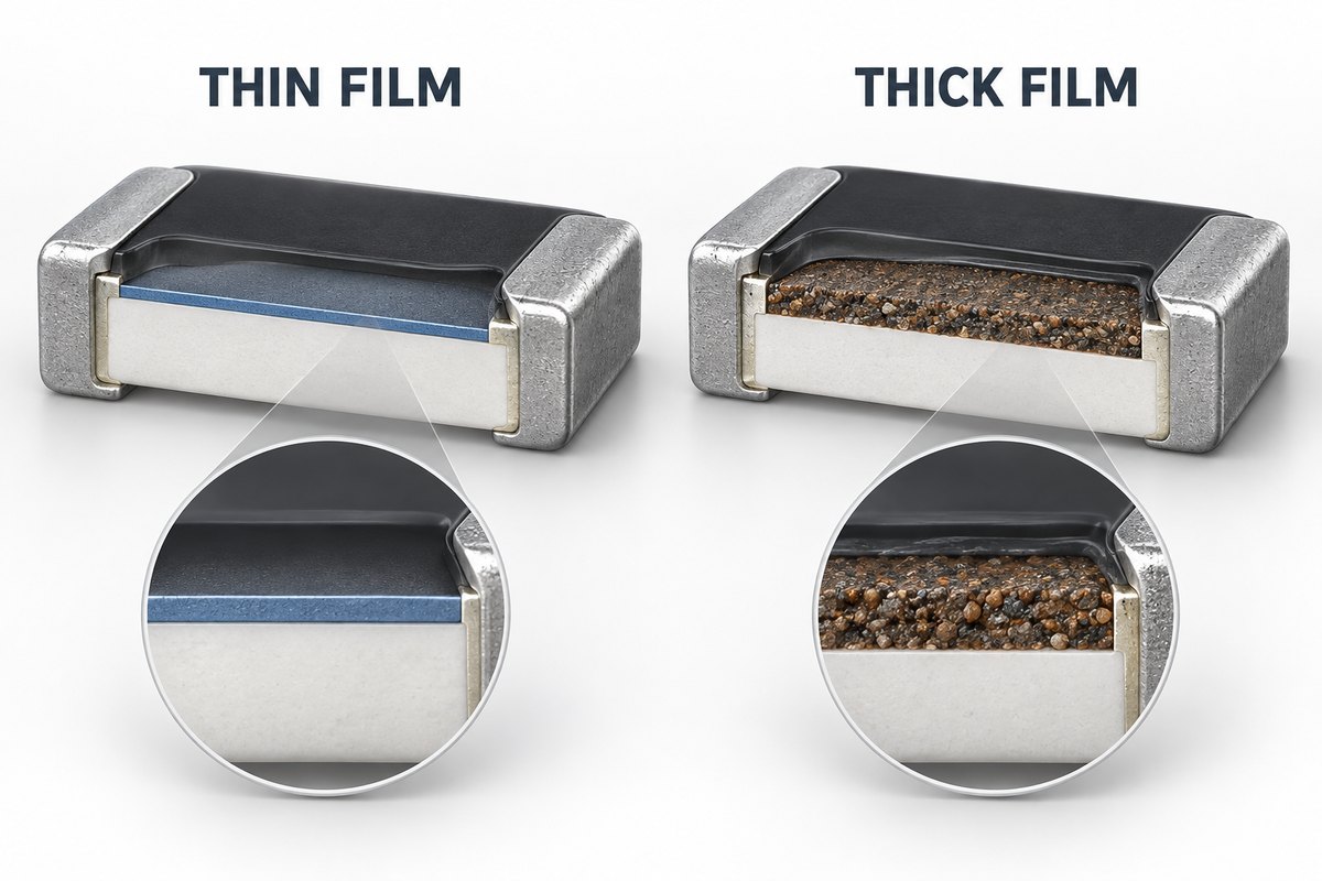
Construction changes performance because current passes through a different material structure. The uniformity of that structure influences how resistance responds to temperature, voltage, electrical load, and time.
- Thin film: A metallic alloy is deposited in a thin, relatively uniform layer. Controlled patterning and trimming can provide low TCR, low excess noise, and stable resistance, which is useful when small changes affect circuit accuracy.
- Thick film: A resistive paste containing conductive material and glass is printed and fired. The process is economical and supports a broad selection of resistance values and packages. Manufacturers can also optimize particular series for pulse, voltage, sulfur resistance, or automotive use.
Construction does not determine performance by itself. Package size, resistance value, trimming geometry, electrodes, protective coating, ambient temperature, PCB heat dissipation, and electrical load also affect the result. The words “thin film” or “thick film” cannot replace a complete datasheet review.
When Should You Choose a Thin Film Resistor?
Choose a thin film resistor when small resistance changes would directly affect measurement accuracy, gain, reference stability, or low-level signal quality. Its customer benefit is not merely a tighter value at room temperature; it is better control of the circuit error as temperature and operating time change.
Choose thin film when the circuit depends on:
- low temperature drift across the specified operating range;
- low excess noise in a sensitive analog or measurement path;
- stable absolute resistance or matched resistor ratios over time.
Typical positions include precision dividers, feedback networks, sensor interfaces, instrumentation amplifiers, reference paths, and matched resistor circuits. In these applications, TCR, load-life drift, humidity performance, and resistance tracking may be as important as initial tolerance.
Do not choose it from tolerance alone. A 0.1% tolerance does not prove that the resistor will remain within the required error across the complete operating range. Approval should be based on the circuit’s total error budget. If lower TCR, lower noise, or greater stability does not improve the application, a thin film part may add cost without improving the finished product.
When Should You Choose a Thick Film Resistor?
Choose a thick film resistor when its specified tolerance, TCR, noise, and drift already satisfy the circuit and the project benefits from lower cost or broader availability. The decision normally falls into two practical situations:
- General-purpose circuit positions: Thick film is often suitable for pull-ups, pull-downs, LED current limiting, biasing, discharge paths, and other functions that do not determine precision performance.
- Pulse, surge, or higher-voltage positions: A thick film part may be appropriate only when the selected series is specifically rated for the real load. The “thick film” label alone does not prove pulse or voltage capability.
For a pulse-loaded position, compare the actual peak voltage, pulse duration, energy, repetition rate, ambient temperature, and allowed resistance change with the manufacturer’s pulse-load data. Average power may hide a damaging short-duration event.
Package size is not proof of pulse survival. A larger resistor can provide more margin, but package size and film technology do not replace the pulse curve, derating rules, and limits of the exact part number.
Can Thin Film and Thick Film Resistors Be BOM Alternatives?
Thin film and thick film resistors are not automatic BOM alternatives, even when their resistance, tolerance, package, and nominal power rating match. A substitution is acceptable only when every specification that matters to the circuit and product qualification remains within the approved limits.
| What must remain equivalent | What to compare |
|---|---|
| Accuracy over operating conditions | Tolerance, TCR, resistance tracking and long-term drift |
| Electrical load capability | Continuous power, working voltage, overload and pulse ratings |
| Circuit behavior | Excess noise, voltage coefficient and relevant frequency behavior |
| Production requirements | Package, terminals, qualification, lifecycle and traceability |
A resistance check proves nominal value—not equivalence. A room-temperature measurement cannot confirm the same temperature drift, noise, pulse survival, or long-term stability. Physical fit on the same PCB land pattern proves only mechanical compatibility.
Use the released MPN or a customer-approved alternative. When purchasing proposes a replacement because of cost or availability, the electrical differences should be reviewed and authorized before the new part enters production. This prevents an invisible sourcing change from altering a validated circuit.
Does Resistor Type Change the PCB Assembly Process?
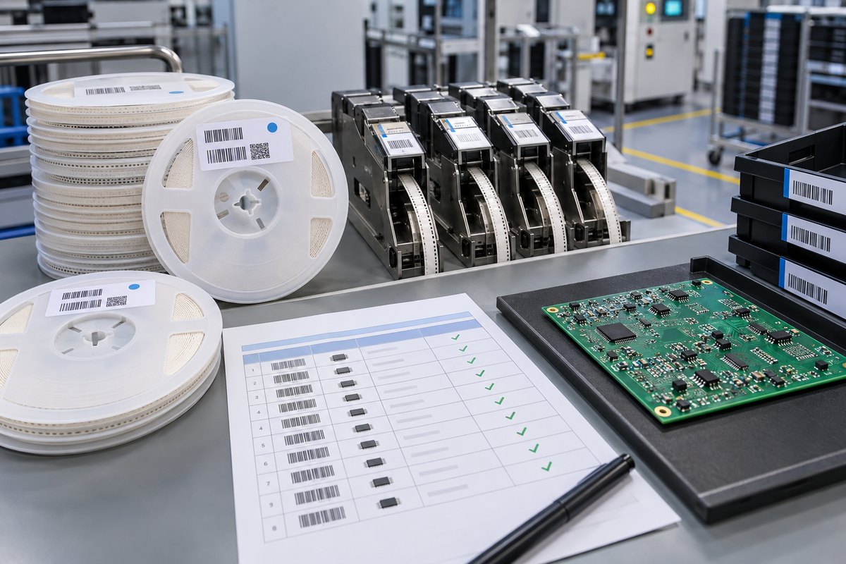
Resistor type alone usually does not change the PCB assembly process. The important distinction is between soldering requirements and material-control requirements.
- Assembly process: Reflow conditions and solder-joint formation are influenced more directly by package dimensions, terminal finish, pad geometry, stencil aperture, solder paste, placement accuracy, and the component manufacturer’s process limits.
- Material control: A thin film resistor and a thick film resistor may look identical after placement, especially when the package has no readable marking. AOI can verify presence, alignment, and visible solder condition, but it normally cannot identify the internal resistive technology.
To preserve the customer’s approved component choice, production records should connect the BOM position with the manufacturer part number, reel label, purchasing record, feeder setup, and required lot traceability. Any proposed alternative should receive documented approval before use.
Agreed functional testing can confirm defined board behavior, but it cannot automatically prove every component characteristic. Test limits and conditions must represent the customer’s validated requirement.
EBest Circuit can manufacture and assemble customer-designed PCBs with approved thin film or thick film resistors from prototypes through repeat production. By connecting the released BOM with component sourcing, SMT setup, inspection, and agreed testing, we help customers keep the validated component decision consistent between batches. For a quotation or BOM and DFM review, send your Gerber files, BOM, assembly drawings, and test requirements to sales@bestpcbs.com.
FAQs About Thin Film vs Thick Film Resistor
Is a thin film resistor the same as a metal film resistor?
Not always. Thin film describes how a resistive layer is formed, while metal film is a broader material and construction term that may include different component formats. Use the exact manufacturer description and datasheet instead of treating the names as interchangeable.
Can thin film and thick film chip resistors use the same PCB footprint?
Yes, when their package dimensions and terminal geometry are compatible. Sharing a footprint does not make their electrical performance equivalent or authorize a BOM substitution.
Can soldering change the resistance of a precision resistor?
Soldering heat can cause a specified resistance shift. Pad design, thermal mass, reflow profile, rework temperature, and the number of heat cycles can influence the stress applied during assembly. The component datasheet should define the permitted change.
Can resistance measurement identify whether a resistor is thin film or thick film?
No. A resistance measurement verifies the measured value under the test conditions, but it does not identify the internal technology or prove TCR, noise, pulse capability, and long-term drift. Identification should rely on the approved part number and material traceability.
Thin film vs thick film resistor selection should protect the finished circuit rather than merely satisfy one resistance value in the BOM. If your project needs controlled component sourcing, PCB fabrication, SMT assembly, inspection, and agreed testing, contact EBest Circuit at sales@bestpcbs.com with the released production files and approved component requirements.