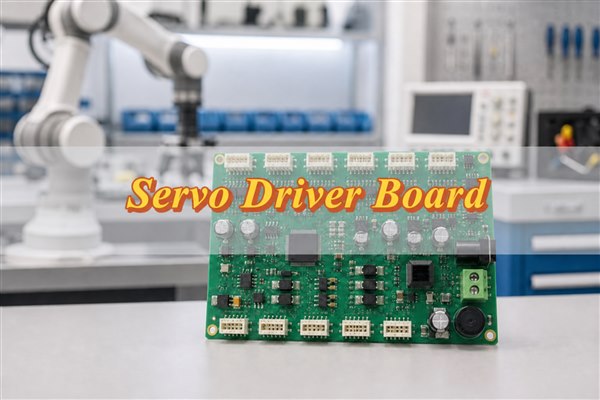
A PCB robot can mean a small robot built on a printed circuit board, a robot control board, or a PCB used inside a robotic system. For engineers and buyers, the real question is not only what the term means. The real question is whether the robot PCB can be manufactured, assembled, tested, and delivered without creating avoidable problems during prototype validation.
EBest Circuit (Best Technology) supports robot PCB and PCBA projects with PCB fabrication, component sourcing, SMT assembly, through-hole assembly, DFM review, inspection, testing coordination, and small-batch production. If your robotics project includes Gerber files, BOM, CPL, stackup notes, impedance requirements, assembly drawings, or test instructions, you can send them to sales@bestpcbs.com for engineering review before production starts.
What Does PCB Robot Mean for Real Robotics Projects?
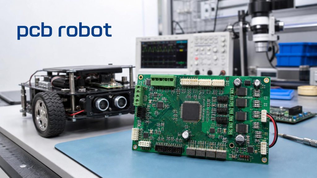
In real robotics projects, a PCB robot usually refers to the printed circuit board used inside a robot or robotic module. The board may control motors, read sensors, manage power, connect communication interfaces, or support firmware programming and testing.
The meaning can change by project type:
- A student project may use a line follower robot PCB.
- A mobile robot may use a motor control PCB.
- An industrial robot may use controller, I/O, sensor, and power boards.
- A robotic camera or inspection system may need high-speed signal routing.
- A service robot may combine sensors, wireless modules, battery circuits, and compact connectors.
The risk is that a robot PCB is often judged only by whether the circuit works on paper. In production, the board also has to survive soldering, cable connection, vibration, current load, heat, enclosure limits, and repeated operation.
For this reason, a useful manufacturing review should connect the circuit files with the real working condition. A robot control board is not only a PCB layout. It is part of a moving product.
PCB Robot vs Robot PCB: Which Meaning Fits Your Project?
PCB robot and robot PCB are often used together, but they do not always describe the same thing.
PCB robot may describe:
- A small robot built directly on a PCB
- A foldable or structural PCB robot
- A DIY robot board
- A robotics-related printed circuit board
- A robot used in PCB production
Robot PCB is usually clearer for manufacturing. It means a PCB used inside a robot system.
For EBest Circuit, the practical focus is robot PCB and robotics PCB manufacturing. The customer’s design team defines the circuit, firmware, MCU, sensor strategy, control logic, and robot function. Our role is to review whether the provided PCB and assembly files can move through fabrication, sourcing, SMT, inspection, testing, and packing reliably.
That distinction matters. If a customer asks us to create the full robot electronics design from scratch, that may go beyond our service scope. If the customer provides production files and needs manufacturing, assembly, DFM, BOM, and testing support, that is where EBest Circuit can help.
How a Robot PCB Connects Motion, Sensors, Power, and Communication
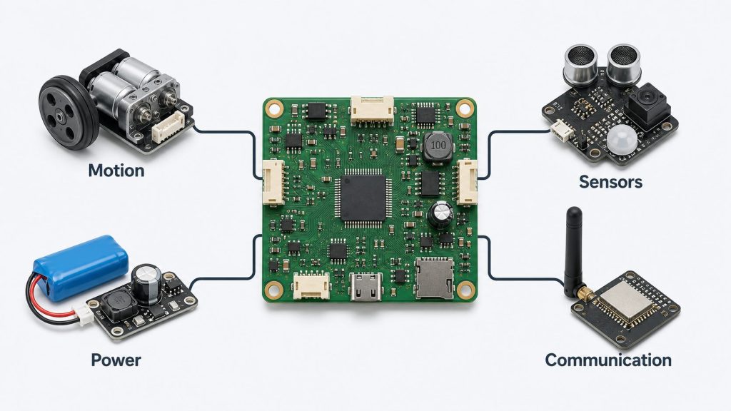
A robot PCB becomes valuable because it connects several demanding functions on one board.
Motion control
Motor drivers, MOSFETs, relays, encoders, and connectors may carry current and receive fast control signals. If copper width, heat dissipation, solder joints, or connector strength are not reviewed, the robot may fail during movement rather than during simple bench testing.
Sensor input
Robotics boards often connect optical sensors, IR sensors, cameras, IMUs, encoders, ultrasonic sensors, pressure sensors, or current sensors. Sensor areas may be sensitive to connector direction, solder cleanliness, signal noise, and mechanical position.
Power management
Robots may use batteries, adapters, DC motors, regulators, charging circuits, and protection devices. A small power issue can cause reset, unstable motor behavior, overheating, or failed validation.
Communication
USB, CAN, UART, RS485, Ethernet, Wi-Fi, Bluetooth, or other interfaces may appear on the same board. If controlled impedance or differential routing is required, the stackup and impedance plan should be confirmed before fabrication.
This is why robot PCB manufacturing cannot be treated like a simple bare board order. The board must match the customer’s electrical files and the physical working environment.
PCB Design for Robotics: What Must Be Ready Before Manufacturing?
For PCB design for robotics, EBest Circuit does not replace the customer’s design team. However, before production starts, certain files must be clear enough for manufacturing.
The most useful customer file package includes:
- Gerber or ODB++ files
- Drill files
- BOM
- CPL or pick-and-place file
- Assembly drawing
- PCB drawing
- Stackup requirement
- Board thickness and tolerance
- Copper thickness
- Surface finish requirement
- Impedance notes, if any
- Firmware file, if programming is required
- Test instructions
- Packing notes
The problem is not only missing files. The bigger risk is inconsistency between files.
For example, a connector may face one direction in the assembly drawing but another direction in the CPL file. A BOM may list a component package that does not match the PCB footprint. A programming header may be present but blocked after assembly. A sensor may need edge alignment, but the panel design may make depaneling risky.
These are the kinds of issues that should be found before SMT starts, not after the customer receives the first prototype.
Robot Controller PCB Risks That Can Delay Prototype Validation
A robot controller PCB often becomes the first board the customer tests during bring-up, especially in a prototype circuit board assembly project. If it fails, the whole robot project slows down.
Common validation risks include:
- Motor driver overheating
- MCU or processor orientation errors
- Unclear programming access
- Sensor connector mismatch
- Wrong polarity on power input
- Weak solder joints on high-stress connectors
- Insufficient copper for current paths
- Missing or inaccessible test pads
- BGA or QFN soldering defects
- Board warpage or poor mechanical fit
- Packing damage after assembly
A low-cost prototype can become expensive if debugging time is lost. Engineers may spend days checking firmware, motor drivers, sensors, or wiring before discovering the issue came from assembly, a wrong component, or an unclear production note.
EBest Circuit’s value is to catch practical manufacturing risks early. For robot controller PCB projects, our engineering review focuses on the details that affect whether the first assembled boards can enter customer testing smoothly.
How EBest Circuit Reduces Robot PCB Assembly Risks Before SMT
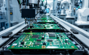
Robot PCB assembly is where many small file issues become real defects. Before SMT, EBest Circuit reviews the project as a complete build, not as separate documents.
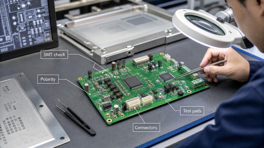
The review focuses on production risk:
- Does the BOM match the PCB footprint?
- Are connector directions clear?
- Are polarity marks visible and consistent?
- Are fine-pitch ICs suitable for the stencil and SMT process?
- Does the panel support stable printing and placement?
- Are BGA, QFN, or hidden solder joints expected?
- Are through-hole parts and hand soldering notes clear?
- Does the board need cleaning after assembly?
- Is firmware programming required?
- Does the customer define a functional test method?
This matters because robot PCBA projects often combine SMT parts, plug-in connectors, power parts, cables, programming interfaces, and test points. If one item is unclear, the board may still be assembled, but the customer may not be able to use it smoothly.
A good robot PCB assembly process is not only about placing components. It is about keeping the customer’s engineering intent visible until the board is packed and shipped.
Line Follower Robot PCB: Small Board, Real Manufacturing Risks
A line follower robot PCB is often used in education, competitions, and early robotics prototypes. It may look simple, but it still has real manufacturing risks.
Typical features include:
- Microcontroller
- Motor driver
- IR sensor array
- Battery input
- Voltage regulator
- Motor connectors
- Programming header
- LEDs or display
- Mounting holes
- Compact board outline
The main challenge is that the board is small, but the functional sensitivity is high.
If the sensor array is not positioned correctly, line detection may be unstable. If the motor current path is too narrow, heat or voltage drop may affect movement. If the battery connector or motor connector is weak, repeated plugging and movement may damage the solder joint. If test access is poor, debugging becomes slower.
For small robotics prototypes, EBest Circuit can review panelization, component direction, soldering process, connector strength, and inspection access before assembly. That helps the customer spend more time testing robot behavior and less time chasing avoidable production issues.
Robot PCB Manufacturing Details That Affect Reliability
Robot PCB manufacturing details can affect whether the board performs reliably after assembly.
Important reliability-related factors include:
- Board thickness
- Copper thickness
- Material Tg
- Via structure
- Surface finish
- Solder mask opening
- Mounting hole plating
- Connector pad strength
- Thermal design around power parts
- Controlled impedance for high-speed interfaces
- Panel design for SMT
- Electrical testing before assembly
For example, a robot board with motor drivers may need stronger attention to copper width, thermal relief, and high current PCB assembly requirements. A sensor board may need clean solder mask definition and stable connector placement. A compact controller with BGA or fine-pitch ICs may need better DFM review, AOI, and X-Ray planning.
EBest Circuit supports FR4 PCB, high-Tg PCB, HDI PCB, flex PCB, rigid-flex PCB, metal core PCB, ceramic PCB, heavy copper PCB, and impedance-controlled PCB projects. For robot PCB projects, the right process depends on the board’s current, density, mechanical space, and testing needs.
How Robotics PCBA Testing Helps Catch Problems Before Delivery
A robotics PCBA should be inspected and tested according to the project risk, with suitable PCB testing and assembly inspection methods. The purpose is not to make the process look complex. The purpose is to catch problems before the boards reach the customer’s test bench.
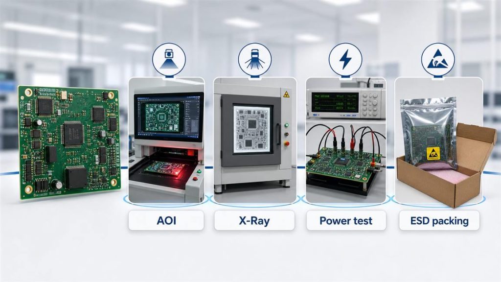
Possible inspection and test steps include:
- Incoming material check
- SPI after solder paste printing
- AOI after reflow
- X-Ray for BGA, QFN, or hidden solder joints
- Visual inspection
- Through-hole solder joint inspection
- Bare PCB electrical test
- Firmware programming, if customer provides firmware
- Power-on check
- Customer-defined functional test
- Connector and polarity inspection
- Final packing inspection
For robot PCBA projects, test points should be planned carefully. Power, ground, programming, communication, motor output, and key sensor signals may need accessible pads if the customer expects production testing.
A robot PCB should not only pass visual inspection. It should arrive ready for bring-up, movement testing, sensor connection, and next-stage validation.
PCB Robot Manufacturing Case Study for a USA Robotics Project
A USA customer needed a small batch of robot controller PCB assemblies for an indoor mobile robot prototype. The project was used for motion control validation before the customer moved toward pilot production.
Project requirements
- Customer region: USA
- Application: Indoor mobile robot controller
- Quantity: 30 pcs prototype PCBA
- PCB type: 4-layer FR4 robot controller PCB
- Material: High-Tg FR4
- Finished thickness: 1.6mm +/-10%
- Copper thickness: 1oz finished outer copper
- Surface finish: ENIG
- Assembly: SMT + through-hole connectors
- Main areas: MCU, motor driver, sensor connectors, power input, programming header
- Test: Power-on check, connector inspection, customer-defined functional test points
- Packing: Single-board ESD packaging after assembly
Main risks
- The motor driver area needed stable soldering and heat awareness.
- Sensor connectors had to face the correct direction for cable assembly.
- Programming access had to remain usable after assembly.
- Small-batch quantity still required clean SMT panelization.
- The customer needed boards that could enter robot bring-up quickly.
EBest Circuit solution
- Reviewed Gerber, BOM, CPL, assembly drawing, and connector notes together.
- Confirmed polarity, Pin 1 direction, and connector orientation before SMT.
- Reviewed panelization and fiducial marks for assembly accuracy.
- Used AOI and visual inspection after SMT.
- Checked through-hole connector solder joints after manual assembly.
- Packed each assembled board separately to reduce handling damage.
Result
The customer received assembled robot controller boards prepared for power-on testing, firmware loading, sensor connection, and motor control debugging.
The value was not only producing 30 boards. The value was giving the customer a clearer manufacturing path from PCB fabrication to sourcing, SMT assembly, connector soldering, inspection, testing notes, and final packing.
Why Turnkey Support Matters for Robot PCB Projects
Robot PCB projects often involve more handoffs than customers expect. PCB fabrication, component sourcing, SMT assembly, through-hole soldering, programming, testing, and packing can each create risk if handled separately.
Turnkey support helps keep project details connected.
For example:
- BOM risk can be checked before SMT scheduling.
- PCB footprint and component package can be reviewed together.
- Panelization can be planned for both fabrication and assembly.
- Connector direction can stay visible from drawing review to inspection.
- Test notes can be prepared before the boards are packed.
- Packing requirements can match the assembled board’s connectors and components.
EBest Circuit has worked in PCB and PCBA manufacturing since 2006. The company serves customers in more than 40 countries and regions, with major export markets including the USA, Germany, and Israel. Quality support includes ISO9001, ISO13485, IATF16949, AS9100D, RoHS, REACH, and UL-related documentation.
For robotics customers, communication stability also matters. Many engineers, quality managers, production leaders, and sales members at EBest Circuit have worked in the company for more than 10 years. When a robot PCB prototype needs quick decisions, stable technical communication can reduce unnecessary delay.
FAQs About PCB Robot and Robot PCB Manufacturing
1. What does PCB robot mean?
PCB robot may mean a robot built on a printed circuit board, a robot-related PCB, or a PCB used inside a robot system. In manufacturing, it usually refers to robot PCB or robotics PCBA production.
2. What is a robot PCB?
A robot PCB is a printed circuit board used in a robot system. It may control motors, read sensors, manage power, connect communication interfaces, or support firmware programming and testing.
3. Can EBest Circuit design the full robot circuit?
EBest Circuit does not replace the customer’s full electronic design team. The customer should provide the circuit design, firmware, control logic, and product requirements. EBest Circuit supports PCB fabrication, DFM review, BOM sourcing, PCBA assembly, inspection, and testing coordination.
4. What files are needed for robot PCB assembly?
Useful files include Gerber or ODB++, BOM, CPL, assembly drawing, PCB drawing, stackup notes, impedance requirements, test instructions, firmware file if programming is needed, and packing notes.
5. Why is testing important for robotics PCBA?
Robotics boards may control motion, sensors, communication, and power. Testing helps catch open circuits, soldering defects, connector issues, polarity errors, programming access problems, and functional risks before delivery.
6. Can a line follower robot PCB be assembled in small batches?
Yes. A line follower robot PCB can be produced as a prototype or small batch. The files should still be reviewed for sensor position, motor current paths, connectors, board outline, component orientation, and test access.
All in all, a robot PCB project becomes easier to manage when fabrication, sourcing, assembly, inspection, and test notes stay connected. If you are preparing a PCB robot, robot controller PCB, sensor board, motor control PCB, or robotics PCBA project, send your files and project notes to sales@bestpcbs.com. EBest Circuit’s engineering team can review the manufacturing path before your boards move into production.