This guide explains how standard resistor values work and how to turn a calculation into a controlled BOM decision. The goal is to reduce sourcing questions, unapproved substitutions, placement errors, and PCBA rework before files reach production.
What Are Standard Resistor Values?
Standard resistor values are preferred nominal resistance values arranged in E-series. Instead of manufacturing every possible resistance, suppliers offer repeatable values across each decade, such as 10 Ω, 100 Ω, 1 kΩ, 10 kΩ, and 100 kΩ.
The number after E indicates how many nominal values appear in one decade. E12 contains 12 values, E24 contains 24, and E96 contains 96. A base value repeats by powers of ten, so 4.7 can represent 4.7 Ω, 47 Ω, 470 Ω, 4.7 kΩ, or 47 kΩ.
Before selecting a part, confirm:
- The acceptable resistance window under worst-case operating conditions.
- Tolerance and temperature coefficient, not only the nominal value.
- Package, power rating, working voltage, pulse capability, and technology.
- A manufacturer part number that is available for the intended production quantity.
A value being standard does not guarantee that every manufacturer offers it in every package or rating. The datasheet and orderable part number remain the final production reference.
Standard Resistor Values Table
The table below lists common base values within one decade. Multiply or divide them by powers of ten to reach the required range. For example, the E24 base value 24 can represent 2.4 Ω, 24 Ω, 240 Ω, 2.4 kΩ, or 24 kΩ.
| Series | Values per decade | Common tolerance association | Base values |
|---|---|---|---|
| E6 | 6 | 20% | 10, 15, 22, 33, 47, 68 |
| E12 | 12 | 10% | 10, 12, 15, 18, 22, 27, 33, 39, 47, 56, 68, 82 |
| E24 | 24 | 5% | 10, 11, 12, 13, 15, 16, 18, 20, 22, 24, 27, 30, 33, 36, 39, 43, 47, 51, 56, 62, 68, 75, 82, 91 |
| E48 | 48 | 2% | Finer three-significant-digit spacing |
| E96 | 96 | 1% | Finer three-significant-digit spacing |
| E192 | 192 | 0.5% or tighter | Verify the selected product family and datasheet |
These tolerance relationships are common associations, not universal purchasing rules. For example, manufacturers also offer many E24 values with 1% tolerance. Always qualify the actual resistor family rather than inferring every specification from the E-series alone.

E Series Resistors and Tolerance
A denser E-series provides more nominal values within each decade. It helps the selected resistance sit closer to the calculated target, but it does not prove that the full circuit will meet its error budget.
| Decision | What can go wrong | What to verify |
|---|---|---|
| Use a wider-tolerance part | Gain, bias, current, or threshold may move outside limits. | Worst-case circuit result at both tolerance limits. |
| Choose a tighter E-series | The nominal value is closer, but drift or ratio error may still dominate. | TCR, matching, long-term stability, and adjacent component tolerances. |
| Reduce BOM variety | A convenient common value may not meet the function. | Whether the substituted value remains inside the approved electrical window. |
For a pull-up or indicator circuit, an E12 or E24 value may provide enough margin. A precision divider, sensor interface, amplifier feedback path, or current-sense circuit may need an E96 value, tighter tolerance, lower TCR, or matched network. The customer engineering team owns the functional limits and released design; the assembly supplier should follow the approved BOM and substitution rules.
E24 Resistor Values for General PCB Assemblies
E24 resistor values offer 24 nominal choices per decade and are widely used where a 5% value provides sufficient circuit margin. The series adds intermediate options such as 11, 13, 16, 20, 24, 30, 36, 43, 51, 62, 75, and 91 that are not present in E12.
E24 is often practical when:
- The function is tolerant of modest resistance variation.
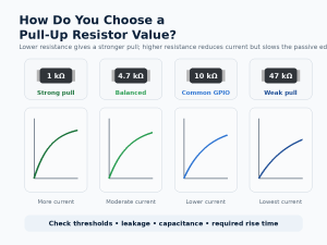
- The value is used for non-critical bias, indication, damping, or ordinary pull-up and pull-down duties.
- Cost, availability, and lower BOM variety matter more than very fine nominal spacing.
- Worst-case calculations confirm that the chosen value and tolerance are safe.
Do not use the application name alone to approve a resistor. A 330 Ω part may work for one LED circuit but overdrive or underdrive another because supply voltage, LED forward voltage, and target current differ. Calculate the function first, then select the E24 value that keeps the full operating range within limits.
E96 Resistor Values for Precision Circuits
E96 resistor values provide 96 nominal choices per decade and are commonly associated with 1% resistors. Their three-significant-digit spacing supports closer selection for analog feedback, sensing, precision division, filtering, and control functions.
| E96 base values (100–976 within one decade) |
|---|
| 100, 102, 105, 107, 110, 113, 115, 118, 121, 124, 127, 130 |
| 133, 137, 140, 143, 147, 150, 154, 158, 162, 165, 169, 174 |
| 178, 182, 187, 191, 196, 200, 205, 210, 215, 221, 226, 232 |
| 237, 243, 249, 255, 261, 267, 274, 280, 287, 294, 301, 309 |
| 316, 324, 332, 340, 348, 357, 365, 374, 383, 392, 402, 412 |
| 422, 432, 442, 453, 464, 475, 487, 499, 511, 523, 536, 549 |
| 562, 576, 590, 604, 619, 634, 649, 665, 681, 698, 715, 732 |
| 750, 768, 787, 806, 825, 845, 866, 887, 909, 931, 953, 976 |
Move the decimal point to reach the required decade: 487 can represent 48.7 Ω, 487 Ω, 4.87 kΩ, or 48.7 kΩ. Before releasing an E96 part, confirm whether absolute tolerance, resistor ratio, TCR, thermal gradients, noise, or long-term drift controls the real accuracy.
A tighter nominal value can also increase sourcing constraints. When alternates are allowed, define the acceptable resistance, tolerance, TCR, package, power, voltage, technology, and qualification requirements rather than approving ‘same value’ substitutions.
How to Find the Nearest Standard Resistor Value
The nearest numerical value is not automatically the safest production choice. The correct direction depends on what failure must be prevented. A higher resistance may reduce LED current, but it may also slow a pull-up edge or change amplifier gain.
Use this selection sequence:
- Calculate the ideal resistance using worst-case supply, load, temperature, and component limits.
- Define the minimum and maximum resistance that keep the circuit inside its approved operating window.
- Select the appropriate E-series and identify the nearest lower and higher standard values.
- Apply resistor tolerance to both candidates and repeat the worst-case calculation.
- Verify power dissipation, derating, working voltage, pulse energy, TCR, package, footprint, and availability.
- Release one exact manufacturer part number and document the approved alternate criteria.
Example: an LED calculation produces 193 Ω. Possible preferred values include 180 Ω and 200 Ω in E24, or 191 Ω and 196 Ω in E96. If excess current is the main risk, the higher value may provide more margin, but brightness and minimum-current requirements must still be checked. The calculation, not the lookup table, approves the part.
Standard SMD Resistor Values for PCBA
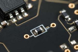
Standard SMD resistor values follow the same preferred E-series used by through-hole resistors. Package size changes assembly and electrical limits; it does not create a separate nominal-value system.
A BOM line that says only ’10 kΩ resistor’ leaves too many production decisions unresolved. A sourcing team may find many 10 kΩ parts with different tolerance, size, power, working voltage, TCR, pulse rating, construction, termination, lifecycle status, and price.
A production-ready resistor BOM line should confirm:
- Nominal resistance with an unambiguous unit, such as 4.7 kΩ rather than 4.7.
- Tolerance, package, power rating, and maximum working voltage.
- TCR, pulse capability, current-sense construction, or other function-specific limits when relevant.
- Manufacturer name, exact manufacturer part number, and lifecycle status.
- Approved alternates or a clear no-substitution instruction.
- Footprint, pick-and-place data, polarity rules where applicable, and assembly drawing consistency.
Very small SMD resistors may have no readable top marking. Reel labels, incoming inspection, feeder setup, material traceability, automated optical inspection, and electrical test requirements therefore matter more than visual identification alone.

EBest Circuit (Best Technology) can support PCB fabrication, BOM and component sourcing review, SMT or through-hole assembly, inspection, and agreed testing coordination within the released project scope. The customer retains responsibility for circuit function, tolerance limits, approved substitutions, firmware, certification, and final product validation.
FAQ About Standard Resistor Values
1. What are the most common standard resistor values?
Common examples include 10 Ω, 22 Ω, 47 Ω, 100 Ω, 220 Ω, 330 Ω, 470 Ω, 1 kΩ, 2.2 kΩ, 4.7 kΩ, 10 kΩ, 47 kΩ, and 100 kΩ. Their popularity does not make them correct for every circuit.
2. What is the difference between E12, E24, and E96?
E12 has 12 nominal values per decade, E24 has 24, and E96 has 96. A denser series gives more choices, but tolerance, TCR, power, voltage, package, and availability still need separate confirmation.
3. Are 1% resistors always E96 values?
No. E96 is commonly associated with 1% tolerance, but tolerance and nominal-value series are separate specifications. Many E24 values are also available as 1% parts.
4. Can I always choose the nearest standard resistor value?
No. Compare both the lower and higher candidates under worst-case circuit conditions. The safe direction depends on whether the function controls current, gain, timing, bias, threshold, damping, or another parameter.
5. Are standard SMD resistor values different from through-hole values?
They use the same preferred-value concept. The available resistance range and electrical limits vary by package, resistor technology, tolerance, power, voltage, and manufacturer.
Ready to move your resistor-controlled PCB assembly into production? Send your Gerber files, controlled BOM, pick-and-place data, assembly drawings, quantity, approved substitution rules, and test requirements to sales@bestpcbs.com. EBest Circuit (Best Technology) will review the package for PCB fabrication and PCBA quotation, helping you identify unclear resistor specifications before sourcing and assembly.