





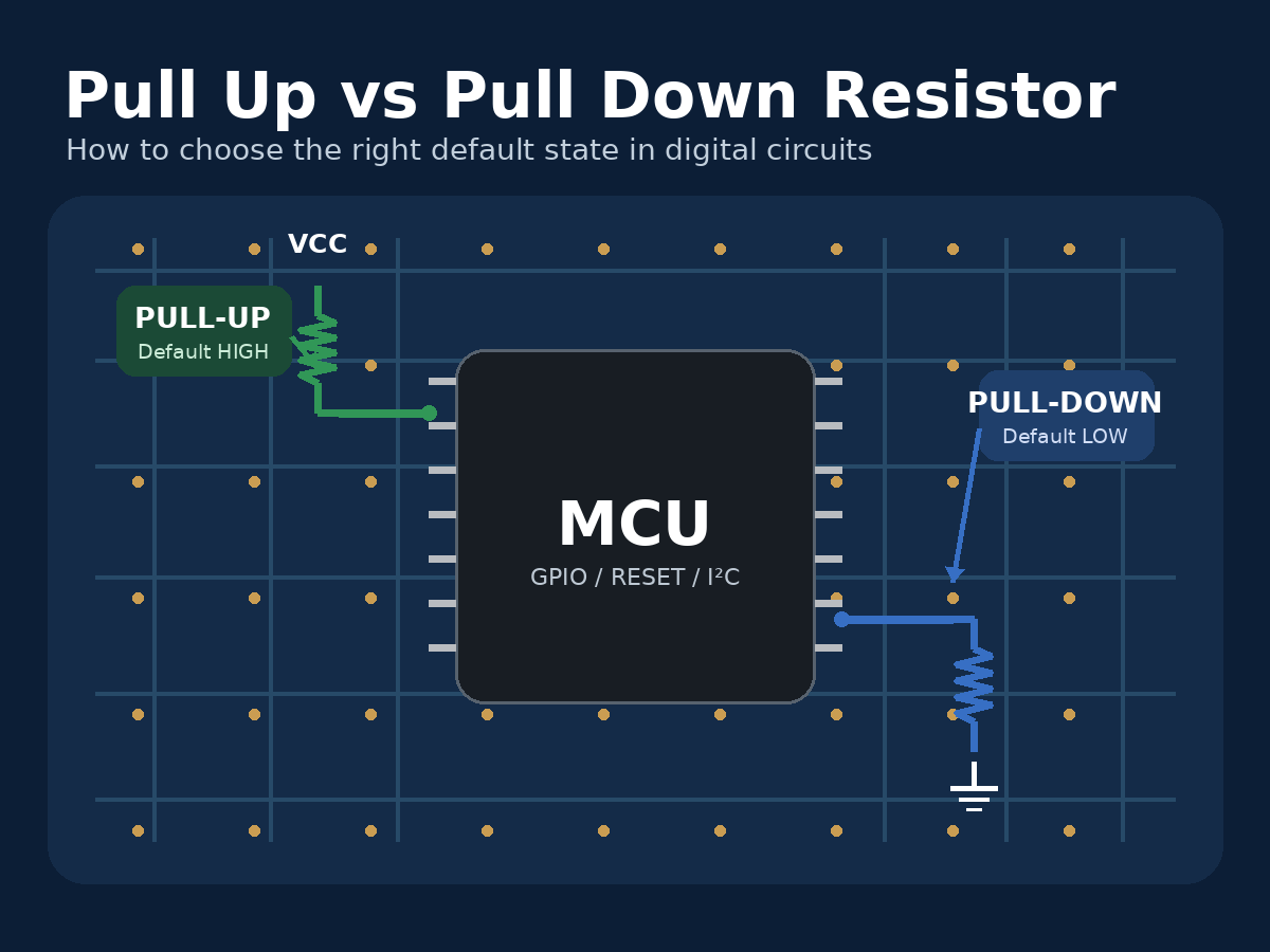
A pull up vs pull down resistor comparison comes down to one basic decision: what logic state should a signal have when no device is actively driving it? A pull-up resistor keeps the signal HIGH by connecting it to the positive supply through resistance, while a pull-down resistor keeps it LOW by connecting it to ground. Both prevent a high-impedance digital input from sitting at an undefined voltage.
The difference is simple, but choosing the right arrangement becomes more important in real circuits involving MCU GPIO, reset and enable pins, sensors, open-drain outputs, I²C buses, and power-up sequencing. This guide explains how pull-up and pull-down resistors work, when to use each type, how to select a suitable resistor value, and what engineers should check before a design moves from schematic to PCB production.
Pull Up vs Pull Down Resistor: What Is the Difference?
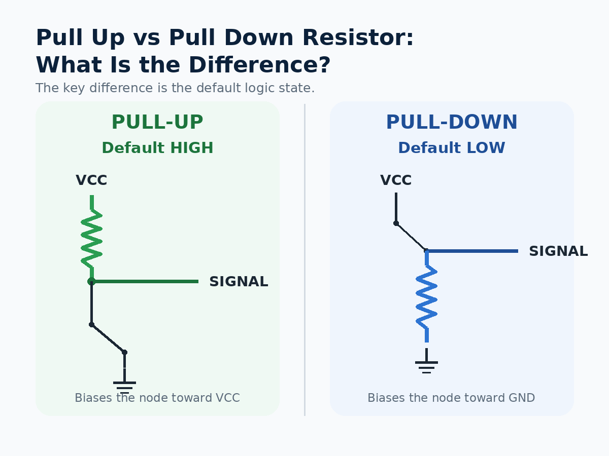
The main difference between pull-up and pull-down resistors is the default logic state they establish.
A pull-up resistor connects the signal to VCC, so an undriven input normally reads HIGH. A pull-down resistor connects the signal to ground, so the same type of input normally reads LOW.
| Design Point | Pull-Up Resistor | Pull-Down Resistor |
|---|---|---|
| Resistor connection | Signal to VCC | Signal to GND |
| Default logic state | HIGH | LOW |
| Typical active state | LOW | HIGH |
| Common switch connection | Signal to GND | Signal to VCC |
| Common uses | Open-drain signals, reset lines, interrupts, MCU inputs | Enable pins, gate control, default-low inputs |
| Logic behavior | Often active-low | Often active-high |
Neither method is inherently better. The correct choice depends on what the circuit should do when the switch, controller, or external signal is inactive.
A useful first rule is:
Default HIGH → use a pull-up.
Default LOW → use a pull-down.
For open-drain or open-collector signals, a pull-up is normally required because the output can actively pull the line LOW but cannot actively drive it HIGH.
How Do Pull-Up and Pull-Down Resistors Work?
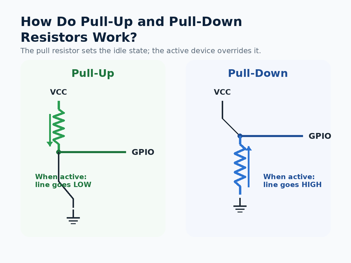
Pull-up and pull-down resistors provide a weak connection to one power rail while allowing another device to override that state.
Pull-up resistor circuit
A pull up resistor circuit typically connects:
VCC → resistor → signal node
A switch, transistor, or open-drain output can then connect the signal node to ground.
When nothing drives the line, the resistor brings the node toward VCC. When the signal is pulled to ground, the resistor limits the current between VCC and GND.
For example, with a 3.3 V supply and a 10 kΩ resistor:
I = V / R = 3.3 / 10,000 ≈ 0.33 mA
Pull-down circuit
A pull down circuit reverses the arrangement:
Signal node → resistor → GND
An external source can then drive the node toward VCC. When that source is removed, the resistor brings the signal back toward ground.
The resistor therefore does two jobs: it establishes a known idle voltage and limits current when another device drives the line in the opposite direction.
This is why simply connecting a signal directly to VCC or GND is not equivalent to using a pull resistor. A direct connection could create excessive current when another device attempts to drive the opposite state.
Why Are Pull-Up and Pull-Down Resistors Needed?
Digital inputs often have very high input impedance. If an input is disconnected and has no pull-up or pull-down path, it can become a floating input.
A floating node may respond to leakage current, residual charge, nearby switching signals, EMI, or capacitive coupling. The voltage can move between valid HIGH and LOW thresholds instead of remaining at a predictable level.
That can create behavior such as:
- an MCU input changing state without a valid command;
- a reset or enable pin activating unexpectedly;
- a MOSFET control node entering an unintended state;
- intermittent sensor or digital-interface behavior;
- unstable operation during startup or controller reset.
The startup condition deserves particular attention in production electronics. Firmware does not configure every GPIO immediately when power is applied. An external pull resistor can establish the required state before firmware runs.
For example, an enable pin that must remain inactive during power-up may use a pull-down resistor even if the microcontroller later controls that signal directly.
Pull resistors are therefore not merely “logic accessories.” They help define circuit behavior during the moments when no active driver is in control.
When Should You Use a Pull-Up or Pull-Down Resistor?
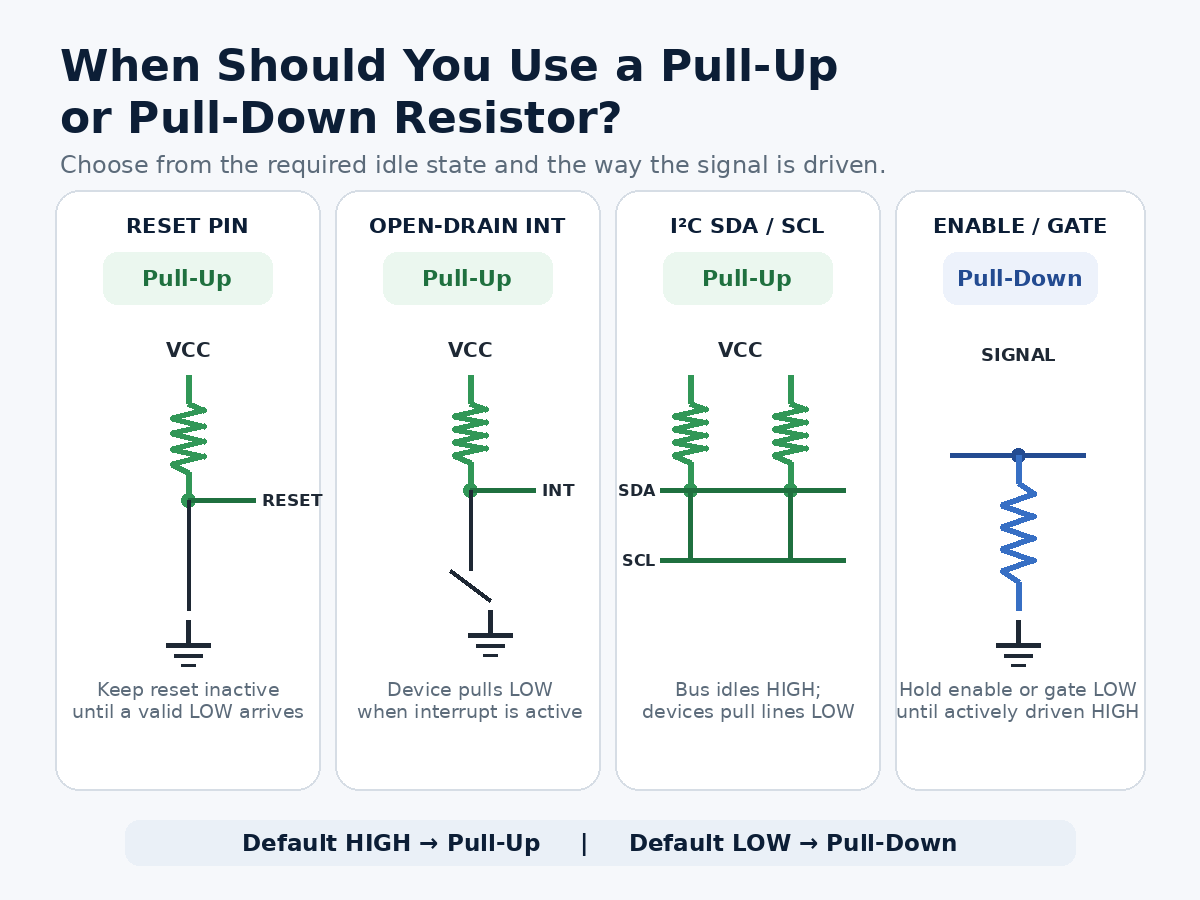
The easiest way to choose between them is to start with the required idle state and then check how the active device drives the signal.
Use a pull-up resistor when:
- the signal should default HIGH;
- a switch or transistor pulls the line toward ground;
- the signal is active-low;
- an open-drain or open-collector output is used;
- reset, interrupt, or chip-select lines should remain HIGH when inactive;
- a communication interface requires a passive HIGH state.
Use a pull-down resistor when:
- the signal should default LOW;
- an external device drives the node toward VCC;
- an enable pin must remain disabled during startup;
- a transistor or MOSFET control input should stay off until commanded;
- a disconnected external input should be interpreted as logic 0.
Open-drain buses are a particularly important case. I²C SDA and SCL lines, for example, are normally pulled HIGH through resistors while connected devices pull them LOW when transmitting.
The decision should also consider power-up behavior. If the correct logic state must exist before the MCU initializes, relying only on firmware configuration may not be sufficient.
In other words, choose the resistor according to what the hardware must do when software is not yet in control.
How Do You Choose a Pull Up Resistor Value?
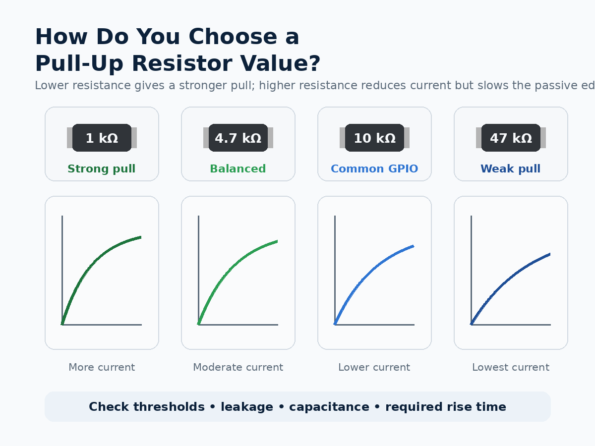
There is no universal pull up resistor value. 10 kΩ is common in slow digital-input circuits, but it should be treated as a starting point rather than a default engineering rule.
The value should be selected by checking four main factors:
- Logic thresholds: the resulting voltage must remain inside the valid HIGH or LOW region specified by the IC.
- Leakage current: a very high resistance can allow device leakage to shift the signal away from the intended level.
- Current consumption: a lower resistance creates a stronger pull but increases current when another device drives the opposite state.
- Capacitance and switching speed: resistance combines with line and input capacitance to form an RC network. Higher resistance generally produces slower passive transitions.
Typical values illustrate the tradeoff:
| Resistor Value | General Behavior | Typical Consideration |
|---|---|---|
| 1 kΩ | Strong pull, faster edge | Higher active-state current |
| 4.7 kΩ | Moderate pull | Common compromise in many digital circuits |
| 10 kΩ | Lower current | Often suitable for low-speed GPIO |
| 47 kΩ or higher | Very low current | More sensitive to leakage, noise, and capacitance |
These are examples, not universal design values.
For I²C and other open-drain interfaces, resistor selection requires particular care because bus capacitance and rise-time limits directly affect the acceptable resistance range.
For a production PCB, the better approach is to check the IC datasheet and interface specification rather than copying a resistor value from another schematic.
Internal vs External Pull-Up and Pull-Down Resistors
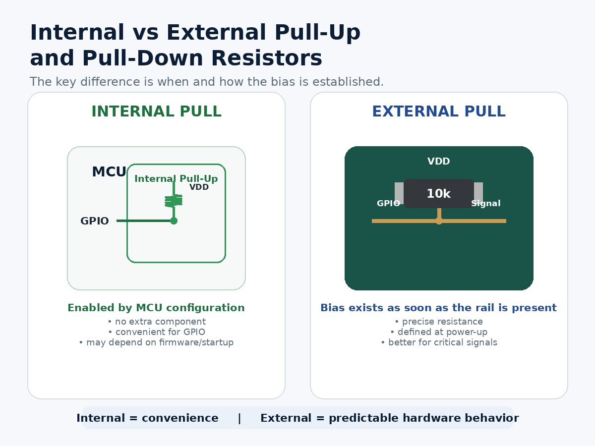
Many microcontrollers provide configurable internal pull-up and sometimes pull-down resistors. These are convenient because they reduce component count and can be enabled through the GPIO configuration.
Internal resistors are often sufficient for:
- simple buttons and switches;
- configuration straps;
- low-speed GPIO inputs;
- non-critical digital signals where the exact resistance is not important.
External resistors provide more design control.
| Internal Pull Resistor | External Pull Resistor |
|---|---|
| No additional component | Requires PCB and BOM space |
| Convenient for GPIO | Resistance can be selected precisely |
| Enabled by firmware/configuration | Can define state immediately at power-up |
| Resistance may vary more widely | Better control of current and RC timing |
| Good for many low-speed inputs | Better for interfaces with defined electrical requirements |
The most important difference in a real product is often when the pull becomes active.
An external resistor works as soon as the relevant power rail is present. An internal resistor may not become active until the MCU reaches a particular startup state or firmware configures the GPIO.
That distinction matters for reset pins, power enables, safety-related control signals, and circuits where another IC becomes active before the main controller.
External components are also usually preferable when rise time, leakage margin, interface compliance, or resistance tolerance must be engineered rather than simply accepted.
How Are Pull-Up and Pull-Down Resistors Used in Microcontroller Circuits?
A pull up resistor in microcontroller designs can appear in many places beyond a simple pushbutton.
Common MCU applications include:
GPIO inputs.
- A pull resistor keeps an unused or externally controlled input at a defined level until another circuit changes it.
Reset and enable pins.
- Pull resistors establish a safe startup condition before firmware begins controlling the board.
Interrupt signals.
- Many sensors and peripheral ICs use open-drain interrupt outputs, making a pull-up necessary to create the HIGH state.
I²C communication.
- SDA and SCL use open-drain signaling and require pull-ups whose values suit the operating voltage, bus capacitance, and required rise time.
Configuration pins.
- Pull-up or pull-down resistors can define boot modes, addresses, or operating states when the system powers on.
Arduino provides a familiar example. INPUT_PULLUP allows supported microcontrollers to enable an internal pull-up for a GPIO input, so a pushbutton can connect between the pin and ground. In that arrangement, the unpressed state reads HIGH and the pressed state reads LOW.
For production MCU boards, however, engineers usually need to look beyond the basic pull up resistor Arduino example. Startup timing, external peripherals, power domains, leakage, signal speed, and what happens before firmware executes can all determine whether an internal resistor is sufficient or an external component is the safer choice.
Common Pull-Up and Pull-Down Resistor Mistakes
Pull resistors are simple components, which makes them easy to overlook during schematic and PCB review. Many problems come from treating a familiar value or reference design as universally applicable.
Common mistakes include:
- Leaving high-impedance inputs floating. An unused or externally disconnected input may need a defined bias rather than being left open.
- Using 10 kΩ automatically. A familiar value can still be too weak, too slow, or unnecessarily strong for a particular circuit.
- Ignoring startup behavior. An internal MCU pull may not control the signal during the earliest stage of power-up.
- Forgetting active-low logic. With a pull-up switch input, the active condition may read LOW rather than HIGH.
- Ignoring bus capacitance. On open-drain interfaces such as I²C, excessive resistance can produce slow rising edges.
- Using the wrong BOM or population option. A schematic may show optional pull resistors while the production BOM or assembly drawing specifies a different DNP/populated condition.
The final check should therefore extend beyond the schematic symbol. Confirm the resistor value, voltage rail, logic polarity, startup condition, populated/DNP status, and interface requirements.
For MCU, sensor, control, and embedded PCBs, these checks are especially useful before fabrication because a small biasing error can otherwise appear later as an intermittent communication, startup, or functional-test problem.
FAQs About Pull Up vs Pull Down Resistor
Can a signal have both a pull-up and a pull-down resistor?
Yes, but the two resistors then form a voltage divider. The resulting voltage depends on their resistance ratio, so this arrangement should only be used when that intermediate bias level is intentional.
Do output pins need pull-up or pull-down resistors?
A normal push-pull output usually drives both HIGH and LOW actively, so it does not need a pull resistor for basic operation. Open-drain or open-collector outputs are different because they typically require a pull-up to create the HIGH state.
Is a 10 kΩ pull-up resistor suitable for every digital input?
No. 10 kΩ is useful in many low-speed circuits, but leakage current, logic thresholds, capacitance, switching speed, and power requirements can make another value more appropriate.
Can pull-up resistors be used with both 3.3 V and 5 V circuits?
Yes, provided the resistor connects to a voltage that is valid for every device on that signal. The pull-up voltage must not exceed the input-voltage limit of any connected IC.
Should an external pull resistor be added if the MCU already has an internal one?
Not necessarily. Internal pulls are convenient for many GPIO inputs, but an external resistor is preferable when the signal needs a defined state before firmware initialization, a specific resistance, stronger biasing, or controlled rise time.
If your MCU, sensor, industrial control, or embedded design is moving from schematic to production, you can send the Gerber/PCB files, BOM, and project requirements to sales@bestpcbs.com. EBest Circuit can support engineering review, PCB fabrication, component sourcing, PCBA assembly, testing, and quotation for the next production stage.
You may also like




Tags: pull down resistor, pull up resistor, pull up vs pull down resistor