A coil on pcb can be formed by routing a copper trace into a spiral, loop or multilayer winding. Unlike a separate wire-wound component soldered to a board, this printed inductor is part of the PCB itself. Its behavior depends on the artwork, copper thickness, layer stack-up and nearby materials. A useful design therefore needs more than an inductance value: resistance, operating frequency, coupling and temperature must also work in the finished assembly.
What Is PCB Coil?
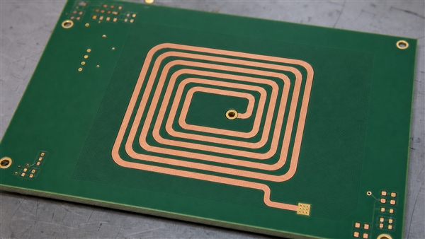
A PCB coil is a conductor patterned on a circuit board to produce a useful magnetic field or inductance. The phrase may also refer loosely to a mounted inductor coil, so first establish whether the winding is etched copper or a purchased component. This article focuses on the etched version, also called a planar inductor or printed coil.
A flat PCB coil normally has two electrical terminals, not a set of independent concentric rings. One terminal begins at the outer turn; the inner terminal often uses a via and a trace on another layer to escape without crossing the winding. A coil PCB can carry surrounding electronics, or it can be a separate sensing or antenna board. A planar PCB coil is therefore a physical winding structure, not a separate component footprint.
What Does a Coil Do in a Circuit?
A coil stores energy in a magnetic field and opposes changes in current. A changing field can also induce voltage in another conductor. These effects let coils act as inductors, antennas, sensors, transformer windings or actuators, depending on their connection and geometry.
The ideal relationships are v = L di/dt and E = 0.5 L I2. A real PCB inductor adds resistance and parasitic capacitance, so it cannot be treated as ideal at every frequency. What is a coil in electronics? It is the winding that provides this magnetic behavior, not necessarily a cylindrical wire component.
Printed Coil vs Wire-Wound Coil
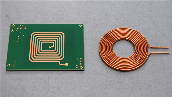
Choose a printed winding for repeatable geometry and low profile; consider a discrete winding when inductance, current or magnetic-core requirements would consume too much board area.
| Design factor | Printed PCB coil | Wire-wound coil |
|---|---|---|
| Geometry | Set by copper artwork and board stack-up | Set by wire, winding and optional core |
| Height | Can be integrated within board thickness | Usually extends above the mounting surface |
| Resistance | Constrained by trace length and cross-section | Wire gauge and winding space offer different trade-offs |
| Inductance per area | Limited for a small air-core spiral | A suitable magnetic core can increase inductance |
| Change control | Requires revised artwork or stack-up | A compatible discrete part may be substituted after validation |
Do not replace a power inductor with an inductor coil on PCB based only on matching nominal inductance. Compare its current waveform, losses, temperature rise, saturation behavior if a core is used, and required transient response. Our guide to inductor placement and selection on PCB covers the separate mounted-component case.
Which Dimensions Control PCB Coil Design?
Outer size, inner opening, turns, trace width and spacing must be considered together. More turns can raise inductance, but fitting them into a fixed footprint can increase resistance and capacitance enough to reduce useful performance.
- Outer dimensions: influence magnetic-field coverage and available winding area.
- Inner opening: determines how tightly the center is filled; tiny inner turns can add more loss than useful coupling.
- Trace width: trades conductor resistance against the number of turns that fit.
- Spacing: must account for fabrication tolerance as well as electrical interaction.
- Copper thickness: changes resistance, etching behavior and finished trace shape.
- Shape: circular, square and rectangular patterns have different field distributions and model coefficients.
For a simple single winding with a bottom-layer escape, double-sided printed circuit boards provide a practical construction. Keep the escape route short and avoid routing it across the active winding on the same copper layer.
How Should You Use a PCB Coil Calculator?
A PCB coil calculator provides a starting estimate, not a finished-board guarantee. Match its model to the shape and layer count, then enter actual manufacturable dimensions. A circular-coil equation should not be applied unchanged to a long rectangular winding.
A PCB coil inductance calculator typically requires turn count, trace width, spacing and inner or outer dimensions. A PCB rectangular coil inductance calculator must also represent both axes. A multilayer PCB coil calculator needs the layer separations and winding connections; simply multiplying a single-layer result ignores mutual coupling.
For a first-order series model, Q = 2 pi f L / RAC, sufficiently below self-resonance. Use AC resistance at the intended frequency, not only a multimeter’s DC resistance. For an LC circuit, f0 = 1 / (2 pi sqrt(LC)) is an initial estimate; the effective capacitance includes the attached circuit and parasitics.
A PCB coil generator or PCB coil design program can automate artwork, but exported tracks still need connectivity and manufacturing checks. Confirm the winding belongs to the intended net, both terminals are accessible, and no polygon fill or copper bridge shorts adjacent turns.
How Do Multilayer PCB Coils Connect?
A multilayer PCB coil can connect windings in series or parallel, but current direction determines whether their fields reinforce or oppose. Follow the entire current path through every via rather than judging polarity from how a spiral looks on screen.
For two series-connected windings, the inductance is L1 + L2 + 2M when the fields aid, and L1 + L2 – 2M when they oppose. Multilayer PCB coil design also changes interlayer capacitance and self-resonance. Parallel windings require balanced connections and current distribution; their benefit is not captured by a universal layer-count multiplier.
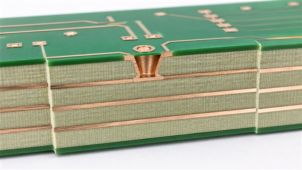
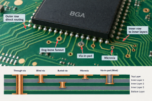
An embedded coil PCB places a winding on internal copper layers. Lamination protects it mechanically, but dielectric thickness and surrounding copper become part of its electromagnetic environment. A PCB bifilar inductor coil uses two closely associated windings; specify their electrical relationship rather than treating all adjacent traces as one series spiral.
Should Copper or a Ground Plane Sit Under the Coil?
Nearby conductive material can alter inductance and introduce eddy-current loss. A solid plane beneath a sensing loop may reduce the very field interaction the design needs. Review adjacent layers, shielding, mounting hardware and the enclosure, not just the visible top copper.
Use a deliberate copper keepout where the application requires an exposed magnetic field, and keep sensitive signal returns outside that keepout correctly routed. Do not remove an entire board’s reference plane without considering return paths. Some applications intentionally use shielding or a magnetic sheet; those features must be included in the model and prototype.
For higher-frequency resonant circuits, RF printed circuit boards allow material and construction choices suited to the circuit. A low-loss laminate does not cancel winding resistance or guarantee a target Q. Low-frequency sensor coils may work well on ordinary FR4 after validation.
What Is a Coil Used For?
PCB coils are useful when their geometry can be matched to sensing, coupling or actuation. The application defines the right compromise, not a universal number of turns.
- Inductive sensing: target movement changes the electrical response of the coil and its readout circuit.
- NFC and RFID: a loop couples to a reader field; tuning and the final enclosure influence operation.
- Wireless power: transmitting and receiving windings exchange energy through magnetic coupling.
- Current measurement: a PCB Rogowski coil surrounds a conductor and responds to changing current.
- Motion: a PCB coil motor uses patterned stator windings interacting with a magnetic rotor.
A PCB Rogowski coil sensor is not just a flat spiral placed anywhere near a wire. PCB Rogowski coil design uses an appropriate closed sensing path and signal conditioning; its induced voltage depends on current change, so steady DC cannot be measured by the coil alone. For motor-specific construction, see our PCB stator motor design guide.
Can a PCB Coil Work as an Electromagnet?
A PCB coil electromagnet produces a field when driven with current, but useful force depends strongly on the magnet or target, air gap, geometry and thermal limit. A shallow printed winding is not automatically a replacement for a high-force solenoid.
For PCB power coil design, estimate copper loss as P = IRMS2R using resistance appropriate to temperature and waveform. Check temperature in the actual duty cycle and enclosure. A copper coil on PCB may need wider tracks or thicker copper, but additional copper does not remove all AC losses.
heavy copper printed circuit boards are relevant when conductor resistance and current handling dominate, including suitable planar transformer windings. Their trace-width and spacing requirements differ from fine-line boards. A PCB coil transformer also needs isolation, coupling and, where applicable, magnetic-core design beyond the winding artwork.
Can You Use a PCB Coil for Wireless Charging?
A wireless charging coil on PCB is possible, but feasibility depends on power, frequency, coupling, losses and thermal performance. A thin printed winding may suit a restricted-height design while being less efficient than a purpose-designed wire or litz-wire winding in another system.
For a PCB wireless charging coil, measure the coupled pair at the expected alignment and separation, including any ferrite and shielding. A proposed Qi PCB coil must meet the applicable system requirements; merely drawing a spiral does not establish Qi compatibility. NFC antenna operation at 13.56 MHz is a different design problem from wireless power transfer and should not inherit its tuning network.
How Do You Test a Coil on PCB?
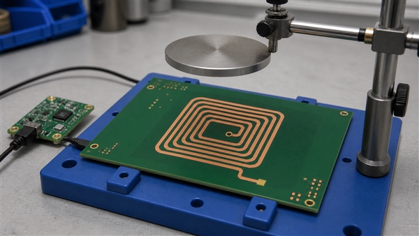
Test connectivity first, then measure inductance and losses at the relevant frequency, and finally verify the complete application. Passing a DC continuity check alone does not establish useful coil performance.
- Inspect trace spacing, terminal escape and vias for opens or cross-turn bridges.
- Measure DC resistance with suitable lead compensation; use a four-wire method when resistance is low.
- Measure inductance and Q with an appropriate LCR meter or impedance analyzer, compensating the fixture.
- Sweep frequency when self-resonance or RF behavior matters.
- Repeat with the final enclosure, target, shield or receiving coil installed.
- Check temperature rise and response over the intended operating range.
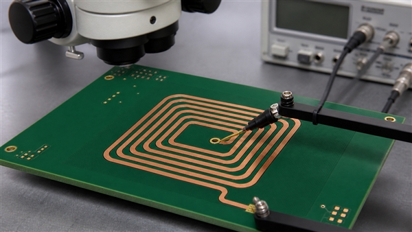
If the result differs from the model, check units, layer spacing, terminal routing, test leads and nearby metal before adding turns. A shorted turn can change inductance substantially while the two terminals still show continuity.
Further Questions About Printed Coils
Can a Rogowski coil on PCB measure steady DC?
No. Its output responds to changing current and normally needs integration to reconstruct the measured AC waveform. A PCB inductor coil used as an energy-storage element has a different function from this current-sensing structure.
What happens when you coil a wire?
The fields from individual turns interact, usually increasing useful inductance compared with the same wire laid straight. Winding spacing, shape and a magnetic core influence the result. PCB traces use the same physical principle with a different conductor geometry.
What is the role of a coil in electronics?
Its role can be energy storage, filtering, coupling or sensing. Identify the connected circuit before deciding whether a coil on circuit board is a power component, an antenna or a sensor.
Can several coils on PCB share one readout?
They can in a designed multiplexed or multichannel system. Switching parasitics, mutual coupling and channel calibration must be included; connecting every coil in parallel is not a general solution.
Is an air-core printed coil free from all current limits?
No. It lacks a ferromagnetic core that could saturate, but copper heating, dielectric limits, driver capability and nearby materials still limit operation.
Our PCB Coil Manufacturing Support
At EBest Circuit (Best Technology), we review the winding geometry together with the board construction. Our FR4 capabilities include ordinary minimum line/space of 4/4 mil and multilayer constructions up to 32 layers, subject to materials, dimensions, stack-up and engineering review. These are fabrication capabilities, not a promise that the finest trace or highest layer count produces the best coil.
We can support copper-thickness checks, optical inspection and open/short electrical testing. Coil inductance, Q, coupling and temperature acceptance require a project-specific test definition; they are not implied by a standard bare-board continuity test.
Conclusion
A reliable coil on pcb starts with the required magnetic function and finishes with measurement in its real surroundings. Keep the current path continuous, use a geometry-appropriate model, control losses and verify the finished stack-up. Contact sales@bestpcbs.com to discuss manufacturing support for your printed winding and surrounding circuitry.