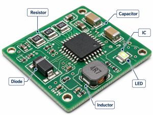
The practical inductor vs capacitor choice starts with the circuit variable that is misbehaving. Choose a capacitor first when you need to hold a voltage steady, supply a brief current pulse, bypass high-frequency noise, smooth voltage ripple, or pass AC while blocking DC. Choose an inductor first when you need to limit the rate of current change, store energy in a switching converter, or block high-frequency current in series with a line. Use both when one part cannot meet the required attenuation or when the circuit needs a tuned response.
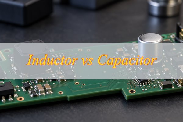
A capacitor opposes a rapid change in voltage, while an inductor opposes a rapid change in current. That first choice still has to survive the part’s impedance curve, applied bias, temperature, source and load impedance, and PCB loop parasitics.
What Is the Main Difference Between an Inductor and a Capacitor?
The main inductor vs capacitor difference is the variable each part controls: capacitance primarily controls node voltage, while inductance primarily controls path current. Their energy storage, connection, and parasitic limits explain when that rule works and when it does not.
| Selection Factor | Capacitor | Inductor |
| Controlled variable | Opposes rapid voltage change | Opposes rapid current change |
| Energy storage | Electric field, E = ½CV² | Magnetic field, E = ½LI² |
| Usual connection | Across a rail or from a node to a reference; in series for AC coupling | In series with the current path |
| Frequency trend | Ideal reactance falls as frequency rises | Ideal reactance rises as frequency rises |
| Typical use | Rail droop, voltage ripple, bypassing, AC coupling | Current ripple, converter energy storage, series filtering |
| Key limit | DC-bias loss, ESR, ESL, ripple current | Saturation, DCR, core loss, temperature rise |
These differences identify the component class, not the finished part. The impedance curve, applied bias, temperature, source and load impedance, and PCB current loop still determine whether the selected value will work.
When Should You Use a Capacitor?
Choose a capacitor first when the circuit needs local charge or a low-impedance path that controls voltage at a node. Match the capacitor to the duration and frequency of the problem rather than increasing capacitance blindly.
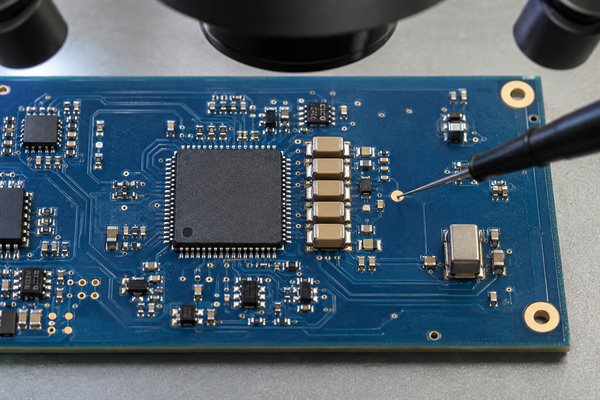
- IC rail droop: Place a decoupling capacitor close to the power pin when a switching edge pulls current faster than the upstream supply can respond. Check the rail at the device pin; effective capacitance, ESL, and loop length matter more than the printed capacitance alone.
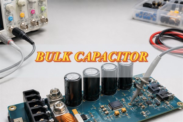
- Longer load transients: Use bulk capacitance when the current step lasts beyond the useful range of a small ceramic capacitor. Estimate the starting value with C ≈ IΔt/ΔV, then include ESR step, tolerance, temperature, and the regulator response time.
- Output voltage ripple: Use a capacitor to absorb the AC component of a rectifier or converter output. Confirm ripple-current rating and ESR heating, and make sure the regulator remains stable with the chosen capacitance and ESR range.
- High-frequency bypass: Use a small capacitor when noise must return locally to a reference plane instead of travelling along the power network. Verify the impedance near the interference frequency and keep the mounting and via inductance low.
- AC coupling: Put a capacitor in series when an AC signal must pass between stages with different DC bias. Set the capacitance from the lowest wanted signal frequency and the surrounding impedance, then check startup transients and distortion.
- Timing or short hold-up: Use an RC network when a changing capacitor voltage provides the timing or temporary energy. Leakage, input bias current, dielectric behavior, and tolerance set the real timing accuracy.
A larger capacitor can increase inrush current, delay startup, or disturb a control loop. If the problem is a fast event at one IC, placement and loop inductance may matter more than adding bulk capacitance elsewhere on the board.
When Should You Use an Inductor?
Choose an inductor first when the circuit must shape current, transfer energy between switching states, or create series impedance without wasting the required DC current in a resistor.
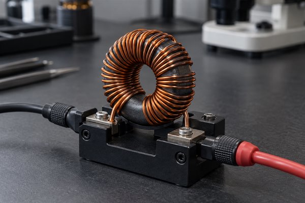
- Switching-converter energy transfer: Buck, boost, and related converters use inductance to set the current slope. Derive the starting value from topology, input and output voltage, switching frequency, and allowed ripple; then check peak current against the saturation curve.
- Current-ripple control: Add series inductance when the load or converter cannot tolerate a large change in current each switching cycle. Measure or calculate peak-to-peak ripple and verify DCR loss, core loss, RMS current, and temperature rise.
- Power-line filtering: Use an inductor when unwanted current must be impeded while DC power continues through the line. Check the impedance at the actual noise frequency and the DC drop at full load.
- RF bias isolation: Use an RF choke to feed bias while keeping the RF signal out of the supply path. The useful band must remain below self-resonance and within the current rating; nominal inductance alone is not enough.
- Lossy noise suppression: Consider a ferrite bead instead when high-frequency attenuation is needed but magnetic energy storage is not. Compare impedance-versus-frequency and DC-bias curves because a bead that looks effective at zero bias can weaken under load.
- Tuning and matching: Use an inductor with capacitance when a resonant or impedance-matching network is intentional. Include component Q, tolerance, pads, vias, and nearby copper in the frequency check.
Do not place a series inductor in front of a fast load merely because the rail is noisy. It can restrict the transient current the load needs. If the observed failure is a local voltage dip at an IC pin, start with the capacitor and its return path.
How Do Inductors and Capacitors Behave Differently in DC and AC Circuits?
At steady-state DC, an ideal capacitor has finished charging and carries no continuous current, while an ideal inductor carries constant current. During startup or a transient, however, capacitor voltage cannot change instantly and inductor current cannot change instantly. That is why a capacitor can support a rail during a brief load step and an inductor can control current rise in a converter.
Frequency changes their ideal impedance in opposite directions. Capacitive reactance is XC = 1/(2πfC), so it falls as frequency rises. Inductive reactance is XL = 2πfL, so it rises as frequency increases. This supports the familiar arrangement of a shunt capacitor for high-frequency node noise and a series inductor for high-frequency line current.
Real parts stop following the ideal trend near self-resonance. Capacitor ESL eventually dominates, and inductor winding capacitance eventually dominates. Read the manufacturer’s impedance curve at the operating frequency and applied bias before relying on the nominal C or L value.
When Should You Use Both an Inductor and a Capacitor?
Use an LC network when one component cannot meet the attenuation or ripple target and the circuit can tolerate the added resonance and transient behavior. Each common use needs a different check.
- Converter output filtering: Add C to hold the output voltage and L to limit switching-current ripple when either part alone would require an impractical value. Check output ripple, load-step response, inductor peak current, and control-loop stability.
- Converter input filtering: Use LC filtering when switching current must be kept out of the upstream supply or cable. Compare filter impedance with converter input impedance and add damping when simulation or measurement shows peaking.
- Second-order low-pass filtering: Combine series L and shunt C when the required roll-off exceeds what a single reactive element can provide. Define passband loss and stopband attenuation first, then verify the response with real ESR, DCR, source impedance, and load impedance.
- Resonant or tuned networks: Use both when the intended function depends on resonance or impedance matching. Start with f0 = 1/(2π√LC), then include tolerance, Q, package parasitics, pads, and layout in the final frequency check.
- Ringing control: Treat an undamped LC peak as a design problem, not as extra filtering. If a load step or frequency sweep shows overshoot, add controlled damping or change the L/C values or topology before release.
The extra order improves attenuation only when the network is stable and correctly damped. Prototype measurements should confirm both frequency response and transient response under the expected source and load conditions.
How Do You Choose Between an Inductor and a Capacitor for Common Circuit Problems?
Match the component to the failing variable, then verify the choice with the measurement or datasheet curve that can disprove it. This keeps the first component choice tied to an observable circuit result.
| Circuit Condition | Preferred Component | Validation Check |
| IC supply dips during switching | Local capacitor | Measure droop at the power pin; inspect ESR step and loop inductance |
| Converter output has voltage ripple | Capacitor | Check ripple current, ESR heating, and regulator stability |
| Switching current ripple is excessive | Inductor | Check ripple, peak current, saturation margin, and temperature |
| Converter must store and transfer energy | Inductor | Verify peak and RMS current, DCR loss, and core loss |
| Signal must pass without its DC bias | Series capacitor | Check low-frequency loss, bias conditions, and startup transient |
| High-frequency noise travels along a power line | Inductor or ferrite bead | Compare loaded impedance, DC drop, resonance, and attenuation |
| One part misses the attenuation target | LC network | Sweep frequency and load; check peaking, damping, and stability |
What Should You Check When Selecting a Real Capacitor or Inductor?
Choose the nominal value only after defining the worst-case voltage, current, frequency, temperature, and allowed circuit error. Then use the following checks to remove parts that will fail under bias or on the assembled PCB.
- Required capacitor value: Calculate from the actual job: transient current and allowed droop, filter impedance, coupling corner frequency, or timing interval. Use the manufacturer’s DC-bias curve to confirm the effective capacitance at the operating voltage.
- Capacitor loss and frequency limit: Check ESR for ripple heating and damping, ESL for fast-transient performance, ripple-current rating for power applications, and self-resonant frequency for bypassing. A higher nominal capacitance can perform worse at the noise frequency if the package and mounting add too much inductance.
- Inductor peak-current margin: Calculate the highest instantaneous current, including ripple and startup or fault conditions. Confirm inductance at that current and keep the peak below the manufacturer’s saturation limit with the required design margin.
- Inductor thermal loss: Use RMS current, DCR, switching frequency, and the manufacturer’s core-loss or temperature-rise data. Passing the saturation-current rating does not prove that winding and core temperature are acceptable.
- Operating range: Check tolerance, temperature dependence, aging where applicable, and impedance versus frequency for both parts. Validate the worst operating corner rather than comparing only room-temperature headline ratings.
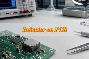
- PCB implementation: Keep a decoupling loop short and its return path direct. Give a power inductor enough copper for current and heat, and separate its magnetic field and switching node from feedback, sensor, and RF traces. Confirm footprint, polarity, height, keep-outs, and assembly clearances against the exact manufacturer part.
The final check is a measurement at the point where the circuit can fail: rail droop at the IC pins, ripple at the converter output, current at the inductor, or attenuation across the filter. A part number is qualified only when the operating waveform and temperature remain inside its real limits.
Common Questions About Inductors and Capacitors
Q1: Can a capacitor replace an inductor?
A1: Not when the circuit needs controlled current ramping or magnetic energy transfer, as in a buck or boost power stage. A capacitor may reduce voltage ripple in the same converter, but it cannot perform the inductor’s current-control function.
Q2: Can an inductor replace a capacitor?
A2: Not for local rail support, AC coupling, or a shunt bypass path. A series inductor can impede noise current, but it cannot provide the immediate local charge that holds an IC supply voltage steady.
Q3: Which component is better for filtering noise?
A3: Choose by noise path. Use a capacitor when unwanted energy should be shunted from a node, an inductor or ferrite bead when unwanted current should be blocked in a line, and an LC network when the attenuation target requires both actions.
Q4: Why use a ferrite bead instead of an inductor?
A4: A ferrite bead is usually selected to dissipate high-frequency noise, while a power or RF inductor is selected for energy storage, current control, or a higher-Q reactance. Compare the bead’s impedance-versus-frequency curve under DC bias before using it in a supply filter.
Q5: Why are capacitors usually connected in parallel and inductors in series?
A5: A parallel capacitor can supply or absorb current at a node while holding its voltage, whereas a series inductor directly opposes a changing current in the path. These are common arrangements, not universal rules; AC-coupling capacitors are a familiar series exception.
Choose C for a voltage problem, L for a current problem, and LC when the circuit needs both series impedance and a shunt path. Then test the decision at the actual frequency, bias, current, temperature, source and load impedance, and PCB layout.
If the choice is still uncertain after calculation—or a prototype shows rail droop, excessive current ripple, filter ringing, or unexpected heating—send the actual design rather than a generic part request. Email sales@bestpcbs.com with your schematic, PCB files, BOM with exact part numbers or approved alternatives, operating voltage, peak and RMS current, switching or noise frequency, ripple or attenuation target, quantity, target date, and test requirements. EBest Circuit can use those inputs for a free DFM and component-sourcing review focused on footprint compatibility, current paths, thermal exposure, layout-sensitive noise, and substitution risks before the design is released.