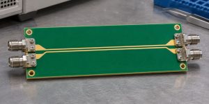
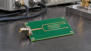
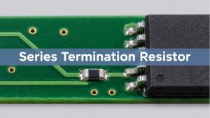
For a conventional point-to-point LVDS link, confirm that the receiver sees one intended differential load matched to the design. An external resistor can double-terminate a receiver that already has the load built in. Check the exact part and operating configuration before changing resistor value, then verify the waveform at the receiver.
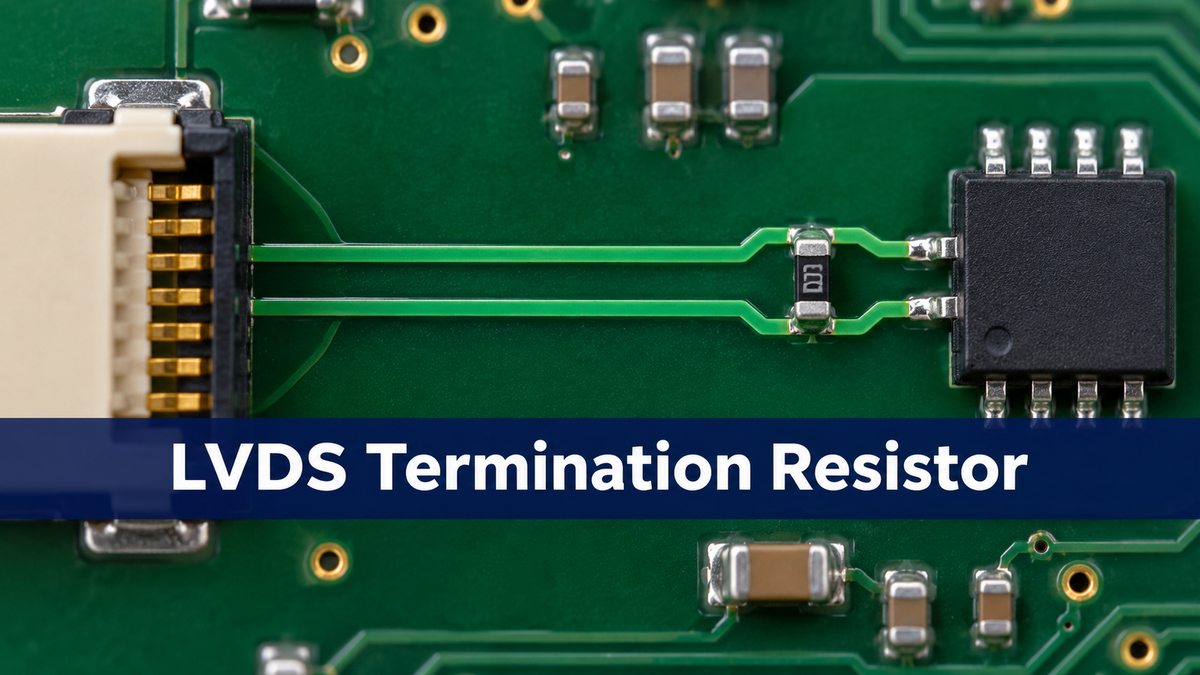
lvds point to point
A point-to-point link has one driver and one receiver on a differential pair. The termination provides a load across the two conductors at the receiving end. Do not copy termination from CAN or a multidrop bus; the topology and component requirements differ.
lvds termination resistor value
Start with the receiver and driver guidance and the target differential impedance. TI’s DS90LV028AQ-Q1 application guidance uses 100 Ω across the receiver input pins. That is a named design example, not a rule for every LVDS receiver or variant. The resistance across the pair is not a resistance from each line to ground.
| Check | Evidence |
| Differential load, Ω | Exact receiver and termination mode |
| Pair impedance, Ω | Target and controlled stack geometry |
| Termination-to-pin distance | Actual routed path and transitions |
| Receiver waveform | Amplitude and timing at defined conditions |
lvds receiver termination
Inspect the complete ordering part number and, for configurable devices, the active setting. TI, for example, distinguishes the DS90LV012A from the DS90LT012A, which includes an input termination. In a hypothetical design with an enabled 100 Ω internal load and a 100 Ω external resistor, their parallel equivalent is 50 Ω. Removing the external part may be appropriate after checking the actual device and topology; it is not a blanket change.
lvds termination resistor placement
For an external load, keep it near the receiver inputs as the device guidance specifies. The length that matters is along the routed conductors, not the straight-line gap between component bodies. A resistor beside the connector can leave a branch or unmatched segment if the receiver is farther inland.
lvds differential impedance
Termination and line impedance are related but are not the same measurement. An ohmmeter reading across a board does not measure the characteristic impedance of the traces. Review the stack and pair geometry separately. On an isolated, unpowered test board, an unexpected DC reading can help identify passive paths, but on-chip termination may not behave the same when unpowered. Consult the device data before relying on that test.
lvds pcb layout
Check the route through the connector, termination pads and receiver escape. Avoid making one leg of the pair take a longer detour through a via or test pad. Where the receiver has the intended built-in termination, do not leave a long unused branch merely to preserve an optional resistor footprint.
| Finding | First action |
| Internal and external loads both active | Restore one intended load and retest |
| No effective load | Confirm receiver option and add the specified load |
| One correct load but persistent ringing | Inspect position, stubs and transitions |
lvds oscilloscope
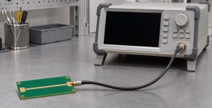
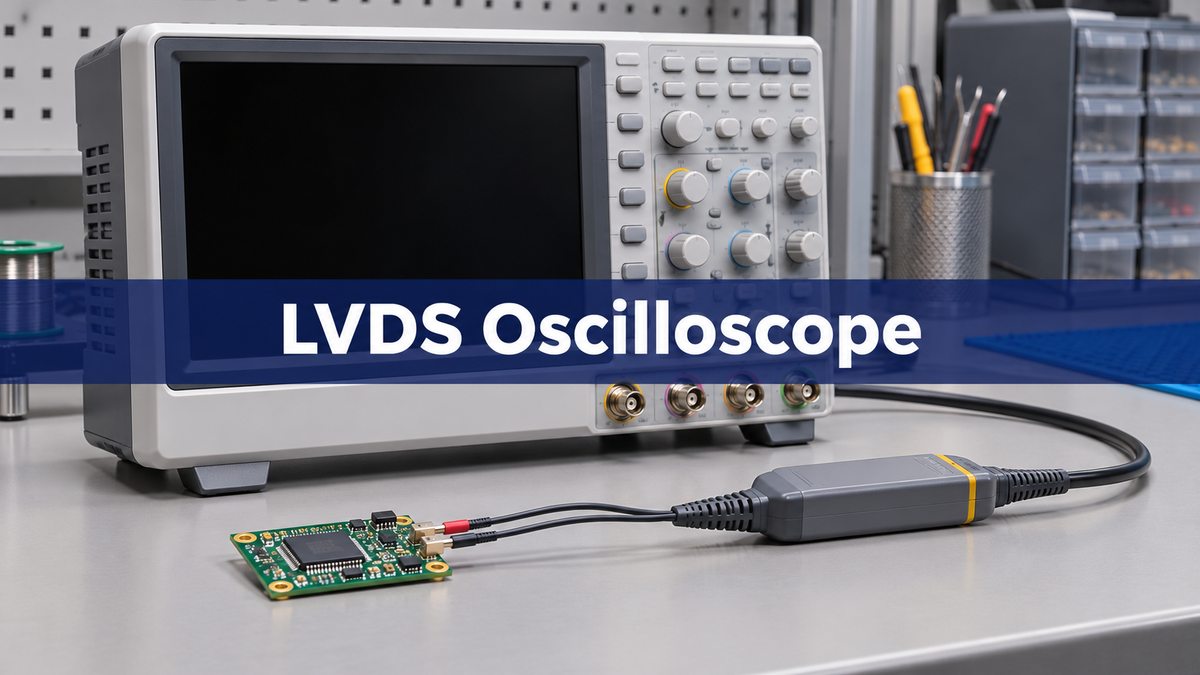
Use suitable differential probing at the receiver with enough bandwidth for the edge rate. Keep the same pattern, fixture and probe location before and after the change. A slow or heavy probe can hide or create the problem. Capture the differential waveform and check common-mode behavior separately when the receiver requires it.
lvds signal integrity
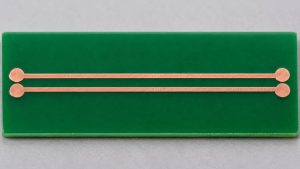
If the duplicate load was removed, compare receiver amplitude, ringing and timing with the approved limits at the intended operating conditions. If the waveform is still poor, inspect the connector, stubs and transitions rather than trying unrelated resistor values. For the uniform trace geometry, see the BestPCBs LVDS routing example.
FAQ
Are two 100 Ω loads equivalent to one 100 Ω load?
No. Two ideal 100 Ω loads in parallel give 50 Ω.
Can the transmitter and receiver both be terminated?
Only if the chosen topology and device specifications call for it. Do not add a second termination to a conventional single-receiver link by default.
Does a resistor near the connector count as receiver termination?
Only if the actual path makes it the appropriate load near the receiving end. Check the route to the receiver pins.
Do I read trace impedance with a resistance meter?
No. A resistance meter can help identify passive loads but does not measure transmission-line impedance.
What if termination is configurable in firmware?
Check the reset state and operating mode, and verify that the setting is active during the measurement.
Can a clean transmitter waveform approve the link?
No. Check at the receiver where reflections, attenuation and timing determine whether the link works.
Can I use this rule for AC-coupled LVDS?
Use the actual device and bias guidance. An AC-coupled receiver may require a different bias and termination arrangement.
Should a test pad be added for the probe?
Use an approved probing arrangement. An asymmetric or long test branch can change the signal you are trying to observe.
Sources
TI LVDS application handbook; TI DS90LV028AQ-Q1 application guidance; TI DS90LV012A and related termination option.
Project Review
For a Best Technology PCB fabrication discussion, send the stackup, differential pair requirements and receiver routing at sales@bestpcbs.com.