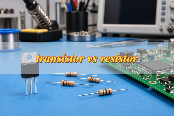
In a transistor vs resistor comparison, the difference is function: a resistor limits current, divides voltage, or sets a bias condition; a transistor switches current or amplifies a signal. Use a resistor to establish electrical conditions and a transistor to control conduction. Many circuits use both because switching current and limiting it are separate tasks.
Transistor vs Resistor: What Are the Main Differences?
A resistor provides resistance; a transistor provides signal-controlled conduction. Their differences are summarized below.
| Property | Transistor | Resistor |
|---|---|---|
| Component type | Active semiconductor device | Passive component |
| Main functions | Switching and amplification | Current limiting, voltage division, and biasing |
| Control | Base or gate signal influences conduction | Voltage and resistance determine current |
| Common terminals | Three on typical discrete devices | Two |
| Main specifications | Voltage, current, drive conditions, and power limits | Resistance, tolerance, power, and voltage ratings |
| Typical use | Switching a load or amplifying a signal | Limiting LED current or setting a signal voltage |
A resistor dissipates electrical energy as heat. A transistor controls energy supplied by the power source and also dissipates some of it. Neither creates energy, and neither can automatically replace the other.
How Do Transistors and Resistors Work?
A resistor follows Ohm’s law: I = V/R. With 5 V across a 1 kΩ resistor, current is 5 mA. Increasing resistance reduces current at the same voltage, but changing voltage also changes current. A resistor therefore limits current without independently keeping it constant.
Its power dissipation is P = VI or P = I²R. Select a resistor that can withstand the expected power, working voltage, temperature, and pulse loading, alongside the calculated resistance.
Common transistors operate in two different ways:
- Bipolar junction transistor (BJT): Base-emitter bias establishes conduction between collector and emitter. The driving circuit must supply suitable base current.
- MOSFET: Gate-to-source voltage controls conduction between drain and source. The required gate voltage depends on the device and its operating conditions.
For switching, the transistor moves between off and conducting states. For amplification, the circuit establishes a bias point so that input changes produce useful output changes. A transistor alone is not a complete amplifier; its behavior depends on the supply, load, and surrounding components.
Transistor vs Resistor: When Should You Use Each?
Choose according to the task your circuit must perform. A resistor suits current limiting, voltage division, and biasing; a transistor suits load switching and signal amplification. Some circuits require both—for example, a transistor switches an LED while a resistor limits its current. The following applications show where each component fits and what to check before selecting it.
- To limit current, use a resistor. For an LED, calculate resistance from the supply voltage, LED forward voltage, and target current. With a 5 V supply, an assumed 2 V LED forward voltage, and a 10 mA target, R = (5 − 2)/0.01 = 300 Ω. Check voltage variation and resistor power dissipation. For tightly regulated current, use an appropriate current-regulating circuit.
- To divide voltage, use a resistor network. Two resistors can scale a voltage for a sensing input. The connected load affects the result, so check its input impedance. A resistor divider is generally unsuitable for powering a load whose current changes.
- To set a default state or bias, use resistors. Pull-up and pull-down resistors establish a signal state when no device is actively driving it. Bias resistors establish analog operating conditions. Lower values draw more current; higher values can increase sensitivity to leakage, interference, or input capacitance.
- To switch a load, use a transistor. A controller signal can command a separate load-current path through a transistor. Check load voltage, operating and startup current, available drive, switching speed, and heat dissipation. Inductive loads also require suitable suppression for the voltage produced at switch-off.
- To amplify a signal, use a properly biased transistor circuit. Select according to signal frequency, required gain, supply voltage, and output load. Resistors commonly establish bias and feedback, so the amplifier may require both component types.
For MOSFET switching, gate threshold voltage does not mean fully on. Check on-resistance at the gate-drive voltage your circuit provides. Insufficient drive can leave the device conducting with excessive resistance, voltage drop, and heating.
Why Are Resistors Often Used with Transistors?
Resistors limit drive current, establish bias, or define a control state around the transistor. Common examples include:
- Base resistor: Limits current entering a BJT base.
- Bias resistors: Establish an amplifier’s operating point.
- Gate resistor: Influences MOSFET switching speed and ringing.
- Pull-up or pull-down resistor: Establishes a defined state when the control output is inactive.
- Emitter or source resistor: Provides feedback that can stabilize operating conditions.
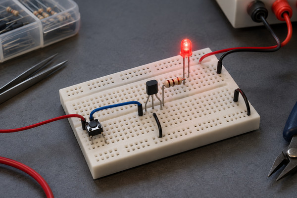
In a simple NPN LED switch, the LED and its series resistor connect from the positive supply to the collector. The emitter connects to ground, and a controller drives the base through a separate resistor. The controller and load circuit share a common ground reference.
The transistor controls whether current flows, the LED resistor controls how much load current flows, and the base resistor limits control current. Removing the LED resistor does not become acceptable simply because a transistor switches the circuit.
Assume a 5 V supply, a 2 V LED forward voltage, a 0.2 V transistor conducting-state drop, and a 10 mA target current:
R = (5 − 2 − 0.2)/0.01 = 280 Ω
Using 300 Ω gives approximately 9.3 mA under those assumptions. The base resistor requires a separate calculation using the controller voltage and required base drive. Its value should account for the transistor’s switching specifications and the controller’s output-current limit.
Can a Transistor and a Resistor Replace Each Other?
Usually, no. Replacing a transistor with a resistor removes controlled switching or amplification. Replacing a resistor with a transistor does not preserve a fixed resistance without additional circuitry and defined operating conditions.
A MOSFET can function as a voltage-controlled resistance within a limited operating range. However, its resistance depends on gate voltage, drain-to-source voltage, temperature, and device characteristics. This is a specific circuit technique rather than a direct substitution.
Before using it this way, check signal range, linearity, power dissipation, and safe operating area. A device suitable for efficient switching is not automatically suitable for continuous operation with substantial voltage and current across it.
FAQs About Transistor vs Resistor
Q1: Does a resistor have polarity?
A1: An ordinary fixed resistor is nonpolarized, so either terminal can connect in either direction. Its markings identify characteristics such as resistance or tolerance rather than polarity. A transistor has assigned terminals, however, so its orientation must follow the datasheet and PCB footprint.
Q2: Why do some transistor packages have more than three pins?
A2: Extra pins may repeat a terminal connection, provide a separate sensing connection, or belong to additional devices inside the package. A Kelvin source pin, for example, provides a separate reference for gate driving. Package pin count does not equal the number of independent transistor terminals; check the internal connection diagram.
Q3: Do transistors with the same package have the same pinout?
A3: No. Matching packages do not guarantee matching pinouts. Visually similar devices may assign their terminals differently. Verify the exact part number, terminal arrangement, and drawing orientation before selecting a PCB footprint or approving a substitute. Physical fit alone does not establish electrical compatibility.
Q4: How can you identify a transistor or resistor on a schematic or PCB?
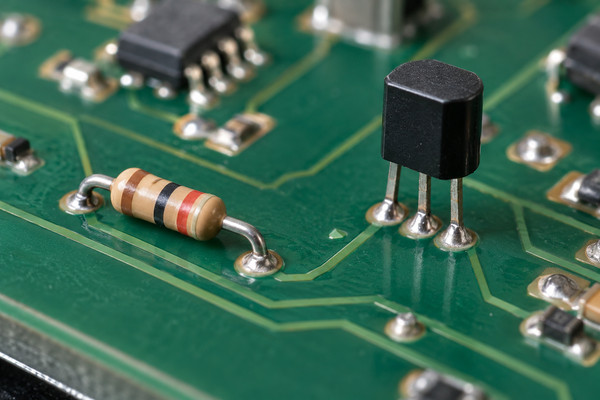
A4: On a schematic, resistors commonly use rectangular or zigzag symbols with R references, while transistors commonly use Q references. On a PCB, match the reference designator to the BOM and schematic. Appearance alone is insufficient, particularly for small unmarked components or devices sharing similar packages.
Q5: Can you measure a resistor while it is installed on a PCB?
A5: Yes, but parallel circuit paths can affect the reading. Remove power and discharge stored energy before measuring. If surrounding components prevent a reliable result, isolating one resistor terminal may be necessary. An unexpected in-circuit reading does not by itself prove that the resistor is defective.
Q6: Does resistance change with temperature?
A6: Yes. The change depends on the resistor’s temperature coefficient, material, and operating range. Heat may come from ambient conditions or the resistor’s own power dissipation. Precision circuits should consider temperature behavior alongside nominal resistance and tolerance, particularly when the accuracy of a resistor ratio affects measurement results.
Q7: What happens if a resistor’s power rating is too low?
A7: Excessive dissipation can cause overheating, resistance drift, or permanent damage. Compare expected dissipation with the manufacturer’s derating curve at the actual ambient temperature. Also check pulse ratings for short-duration loads: a resistor that tolerates the average power may still be unsuitable for repeated high-energy pulses.
Q8: Does a MOSFET gate draw current?
A8: An insulated MOSFET gate draws very little steady-state current, but current flows while its capacitances charge and discharge. Faster switching generally requires greater momentary drive current. Gate leakage and switching current are different quantities, so a voltage-controlled gate should not be interpreted as requiring no current under all conditions.
Q9: Can transistors and resistors exist inside the same chip?
A9: Yes. Many integrated circuits contain both transistor and resistor structures, alongside other elements. Their construction differs from discrete components, but their electrical roles remain recognizable. Integration can improve matching and reduce external component count, although internal devices still have limits associated with voltage, temperature, and manufacturing variation.
Q10: How does a capacitor differ from a transistor and a resistor?
A10: A capacitor stores energy in an electric field and is used for filtering, coupling, decoupling, and timing. A resistor establishes voltage-current relationships and dissipates energy, while a transistor provides controlled conduction. These complementary functions explain why all three commonly appear together in electronic circuits.
Conclusion
The transistor vs resistor choice follows the task: use resistors for current limiting, voltage division, and biasing; use transistors for switching and amplification. Use both when the circuit requires controlled conduction alongside defined currents or voltages. Verify electrical ratings, drive conditions, and thermal limits before finalizing component choices.
EBest Circuit provides PCB manufacturing and assembly for prototypes and volume production. Send your Gerber files, BOM, quantity, and assembly requirements to sales@bestpcbs.com for technical guidance and a quotation. Include exact component specifications and permitted substitutions to keep production aligned with your approved requirements.