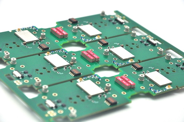
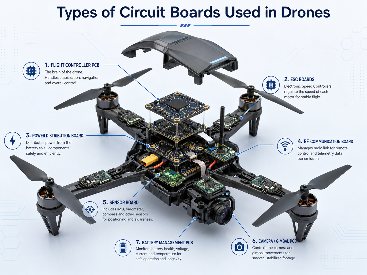
The main types of circuit boards used in drones include flight controller PCBs, ESC boards, power distribution boards, RF communication boards, sensor boards, camera and gimbal boards, battery management boards, flexible PCBs, rigid-flex PCBs, HDI PCBs, and high-current power PCBs. Each board supports a different task: stable flight, motor control, power delivery, image transmission, navigation, sensing, or system integration.
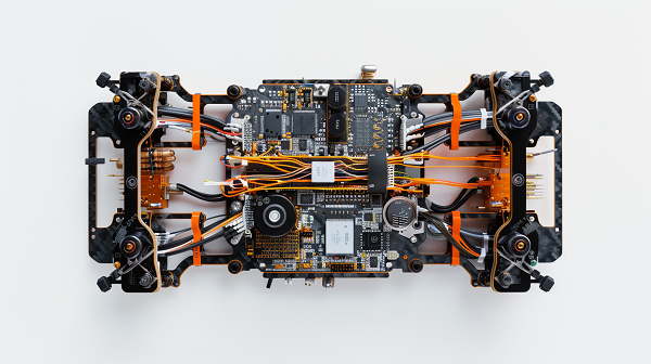
A drone is not controlled by one single board. It is a compact electronic system where weight, vibration, heat, current, signal noise, and mechanical space all affect PCB selection. Choosing the right PCB structure helps improve flight stability, reduce assembly risk, and extend service life in real operating environments.
What Are the Types of Circuit Boards Used in Drones?
The types of circuit boards used in drones are specialized PCBs designed for flight control, power conversion, motor driving, communication, sensing, imaging, and battery protection. A consumer camera drone, FPV racing drone, agricultural UAV, and industrial inspection drone may all use different PCB combinations.
In simple terms, a drone PCB carries signals and power between the battery, processor, sensors, motors, receiver, camera, and communication modules. Some boards handle low-voltage logic. Others carry high-current motor power. High-end drones may use rigid-flex or HDI PCB structures to reduce connectors, save weight, and fit complex mechanical layouts.
| Board Type | Main Function | Common Location in Drone | Typical Design Focus |
|---|---|---|---|
| Flight controller PCB | Controls flight attitude and stability | Central body | Signal integrity, IMU placement, vibration control |
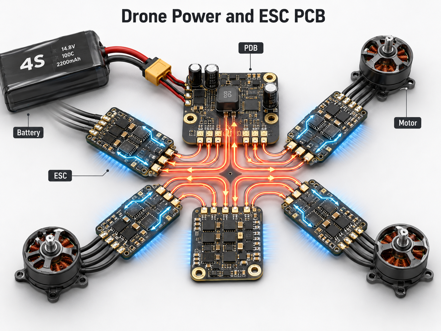
| ESC PCB | Drives brushless motors | Arm area or integrated stack | High current, heat dissipation, MOSFET layout |
| Power distribution board | Distributes battery power | Central frame or stack | Copper thickness, current path, voltage drop |
| Sensor PCB | Collects motion, altitude, GPS, optical data | Body, bottom, or navigation module | Noise control, stable reference ground |
| RF communication PCB | Handles control, telemetry, GPS, Wi-Fi, and video | Antenna or communication module | Impedance control, shielding, RF material |
| Camera and gimbal PCB | Supports video, image sensor, and stabilization | Camera module or gimbal | High-speed signal, flexible connection |
| BMS PCB | Protects the battery pack | Battery module | Current sensing, protection, thermal design |
| Rigid-flex PCB | Connects moving or folded parts | Arms, gimbal, camera, compact body | Reliability, space saving, bend control |
| HDI PCB | Supports compact high-density electronics | Flight controller, camera, AI module | Fine lines, microvias, compact routing |
Why Are Drone Circuit Boards Important for Flight Reliability?
Drone circuit boards are important because they directly affect flight control, power stability, signal accuracy, and long-term reliability. A small layout issue can create unstable sensor readings, motor noise, voltage drop, overheating, or communication loss.
Unlike many static electronics, drones face constant vibration, rapid current changes, airflow cooling differences, outdoor humidity, impact shock, and compact assembly pressure. The PCB must remain electrically stable while the frame moves and motors generate noise. This is why a drone board should be treated as both an electronic component and a structural reliability component.
For example, the flight controller board must keep the IMU sensor clean from vibration and electrical noise. The ESC board must handle pulsed current without overheating. RF boards must maintain signal quality near motors, batteries, and carbon-fiber frames. Each PCB has a clear job, and each job affects flight safety.
How Do Drone PCBs Work Inside a UAV System?
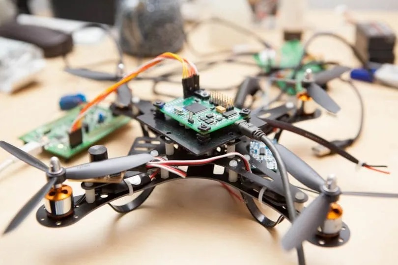
Drone PCBs work by connecting control signals, power rails, sensors, motor drivers, and communication modules into one coordinated UAV system. The flight controller receives data from sensors, calculates attitude corrections, and sends commands to the ESCs. The ESCs then drive the motors according to those commands.
Power usually starts from a lithium battery pack. It passes through a power distribution board, BMS, voltage regulator, or integrated AIO board. Low-voltage rails power the MCU, receiver, GPS, IMU, barometer, camera, and telemetry module.
A stable drone PCB system needs clean separation between noisy power circuits and sensitive signal circuits. Good grounding, layer stack-up, short return paths, shielding, and controlled impedance all help the drone process data accurately during flight.
Main Types of Circuit Boards Used in Drones
The main types of circuit boards used in drones can be divided by function and PCB construction. Function tells you what the board does. Construction tells you how the board is built.
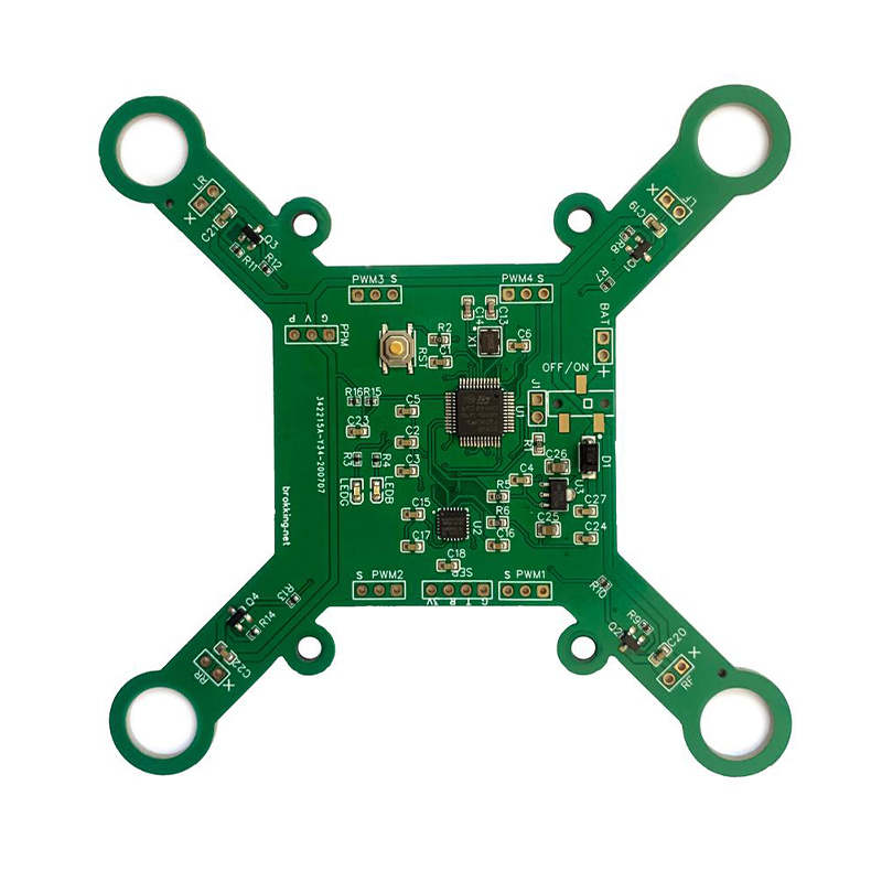
Flight controller PCB is the brain of the drone. It carries the MCU, IMU, barometer, memory, connectors, and power regulation circuits.
ESC PCB converts control signals into three-phase motor drive output. It usually includes MOSFETs, gate drivers, current sensing, capacitors, and thermal copper areas.
Power distribution board distributes battery current to ESCs and other modules. Some drones use a separate PDB, while compact drones may integrate it into the flight controller or ESC stack.
Sensor PCB supports GPS, compass, optical flow, ultrasonic, LiDAR, airspeed, or environmental sensing.
Communication PCB handles receiver signals, telemetry, Wi-Fi, Bluetooth, RF links, GPS, or video transmission.
Camera and gimbal PCB supports image sensors, motors, video signals, and flexible connections across moving joints.
BMS PCB protects battery packs through over-current, over-voltage, under-voltage, temperature, and balancing functions.
AIO PCB combines several functions, such as flight controller, ESC, PDB, receiver, or video transmitter, into one compact board.
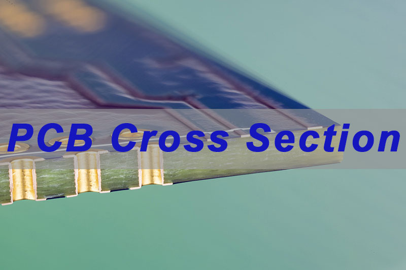
What PCB Materials Are Used in Drone Electronics?
Drone electronics commonly use FR4, high-Tg FR4, flexible polyimide, rigid-flex structures, metal core substrates, high-frequency laminates, and sometimes ceramic substrates for special thermal or RF applications. The material choice depends on weight, current, heat, frequency, bending, and cost.
FR4 is widely used because it offers good mechanical strength, stable processing, and reasonable cost. High-Tg FR4 is preferred when the drone board faces higher operating temperature or dense multilayer assembly. Flexible polyimide is useful in camera modules, gimbals, foldable arms, and compact sensor routing. Rigid-flex PCB is selected when the design needs fewer connectors and better vibration resistance.
For RF modules, controlled dielectric properties matter more. For high-current ESC or power boards, copper thickness, thermal vias, copper balance, and heat spreading become more important than simple material naming.
| Material or Structure | Typical Drone Use | Strength | Limitation |
|---|---|---|---|
| Standard FR4 | Flight controller, sensor board, receiver board | Cost-effective and stable | Limited thermal performance for high-power zones |
| High-Tg FR4 | ESC, dense multilayer controller, industrial UAV boards | Better thermal endurance | Higher cost than standard FR4 |
| Flexible polyimide PCB | Gimbal, camera, foldable modules | Lightweight and bendable | Needs bend radius control |
| Rigid-flex PCB | Compact UAV systems, camera drones, industrial drones | Reduces cables and connectors | Higher fabrication cost |
| HDI PCB | Mini flight controller, AI camera module, high-density system board | High routing density | Requires tighter DFM control |
| Metal core PCB | LED, power, thermal modules | Strong heat spreading | Less suitable for complex multilayer signal routing |
| RF laminate | GPS, telemetry, video transmission | Better high-frequency performance | Higher material and process cost |
| Ceramic PCB | High-power or special thermal modules | High thermal conductivity and insulation | Higher cost and application-specific use |
Key Features, Advantages, and Limitations of Drone PCBs
Drone PCBs are designed for lightweight assembly, reliable power delivery, stable signal processing, and resistance to vibration. Their advantages come from integration. A well-designed board can reduce wires, save space, simplify assembly, and improve electrical performance.
The main limitation is design compromise. A drone PCB often has to balance weight, current capacity, heat dissipation, RF performance, mechanical strength, and cost in a small area. Increasing copper thickness helps current capacity but adds weight and may affect etching precision. Adding more layers improves routing and shielding but raises cost. Choosing rigid-flex saves connector space but requires stricter fabrication and assembly control.
The best PCB choice is rarely the most advanced option. It is the structure that matches the drone’s payload, flight time, motor current, communication distance, sensor accuracy, and production volume.
Rigid PCB vs Flexible PCB vs Rigid-Flex PCB vs HDI PCB for Drones
Rigid PCB, flexible PCB, rigid-flex PCB, and HDI PCB solve different drone design problems. Rigid PCB is suitable for stable flat assemblies. Flexible PCB is useful for motion and tight routing. Rigid-flex PCB improves reliability by replacing connectors. HDI PCB supports compact high-density designs.
| PCB Type | Best For | Typical Drone Example | Relative Cost | Main Design Concern |
|---|---|---|---|---|
| Rigid PCB | Standard flat electronic modules | Flight controller, ESC, receiver | Low to medium | Layer stack-up, vibration, thermal balance |
| Flexible PCB | Moving or narrow spaces | Camera, gimbal, foldable arms | Medium | Bend radius, stiffener, copper cracking |
| Rigid-flex PCB | Compact and vibration-prone systems | Industrial UAV, camera drone, aerospace-style UAV module | High | Stack-up transition, impedance, assembly yield |
| HDI PCB | Miniaturized high-density electronics | Small flight controller, AI vision module, advanced camera board | High | Microvia reliability, fine-line manufacturing |
| Metal core PCB | Heat-heavy modules | LED, power, high-current thermal board | Medium to high | Insulation layer, thermal path, mechanical fit |
For most standard drones, multilayer FR4 PCBs remain practical. For compact camera drones and high-end industrial UAVs, rigid-flex and HDI designs often provide better space efficiency and reliability.
How to Choose the Right Drone Circuit Board for Your Project
Choose a drone circuit board by matching the board function with electrical load, mechanical space, vibration level, signal speed, operating environment, and production volume. Start from the drone’s mission, then define PCB requirements.
For FPV racing drones, weight, high-current ESC performance, compact AIO design, and vibration resistance are key. For camera drones, signal quality, gimbal flex life, image module routing, and compact packaging matter more. For agricultural drones, current handling, moisture resistance, connector strength, and serviceability are more important. For inspection drones, reliability, long flight time, RF stability, and rugged assembly often lead the design.
| Project Need | Recommended PCB Direction | Reason |
|---|---|---|
| Small FPV drone | AIO PCB, HDI PCB, high-Tg FR4 | Saves space and weight |
| Long-range UAV | Controlled impedance RF PCB, stable power board | Improves communication and telemetry reliability |
| Camera drone | Rigid-flex PCB, flex PCB, HDI camera board | Supports compact moving modules |
| Heavy-lift drone | High-current ESC PCB, thick copper PDB | Handles motor current and thermal stress |
| Industrial inspection UAV | Rigid-flex or multilayer FR4 with strong QC | Improves vibration and field reliability |
| Outdoor agricultural drone | Conformal coating, robust connectors, high-current design | Handles moisture, load, and field service conditions |
Where Are Drone PCBs Used Across Different UAV Applications?
Drone PCBs are used in consumer drones, FPV racing drones, industrial inspection drones, agricultural UAVs, mapping drones, logistics drones, public safety drones, research UAVs, and robotics platforms. Each application puts a different priority on the circuit board.
Consumer drones value compact size, stable camera transmission, clean power, and consistent assembly. FPV drones value low weight, fast response, and high-current ESC performance. Industrial drones need stronger reliability under vibration, temperature changes, and long operating hours. Agricultural drones need robust high-current power delivery and environmental protection. Mapping drones need stable GPS, camera, and storage interfaces.
Drone PCB Design Guidelines for Weight, Power, EMI, and Vibration
Drone PCB design should balance four core factors: weight, power, EMI, and vibration. These factors decide whether the board performs well in real flight conditions.
For weight control, avoid oversized boards, unnecessary connectors, excessive copper where it is not needed, and overbuilt layer counts. For power delivery, keep high-current paths short and wide, use suitable copper thickness, apply thermal vias where needed, and avoid narrow neck-downs near MOSFETs or battery inputs.
For EMI control, separate motor power circuits from IMU, GPS, RF, and analog sensing areas. Use continuous ground planes where possible, keep return paths short, and route high-speed or RF signals with impedance control. For vibration, use proper mounting holes, reinforced connectors, component placement awareness, and flexible interconnects where repeated motion occurs.
Common Drone PCB Failures and How to Prevent Them
Common drone PCB failures include overheated ESC circuits, cracked solder joints, connector fatigue, voltage drop, RF interference, IMU noise, moisture corrosion, and flexible circuit cracking. Most of these problems can be reduced during design review and manufacturing planning.
| Failure Mode | Common Cause | Typical Symptom | Prevention Method |
|---|---|---|---|
| ESC overheating | Poor MOSFET layout, narrow copper, weak heat spreading | Motor cut-off, burnt components | Use wider copper, thermal vias, copper balance, thermal simulation review |
| Voltage drop | Long or narrow high-current paths | Brownout, unstable controller reset | Shorten power path, increase copper width and thickness, improve PDB layout |
| IMU noise | Poor placement near vibration or switching circuits | Drift, unstable hover, flight correction errors | Isolate IMU area, improve grounding, separate noisy circuits |
| RF signal loss | Poor antenna layout, impedance mismatch, motor EMI | Reduced control distance or video drop | Controlled impedance, shielding, antenna clearance |
| Cracked solder joints | Vibration, heavy components, weak mounting | Intermittent failure | Use proper mounting, adhesive support where needed, strong inspection |
| Flex cracking | Tight bend radius or wrong stack-up | Camera or gimbal signal loss | Define bend radius, use suitable copper, add stiffener |
| Corrosion | Moisture, field exposure, flux residue | Leakage, unstable signal, visible oxidation | Clean assembly, conformal coating, proper packaging |
| Delamination | Heat, material mismatch, poor process control | Blistering, open circuits | Select proper Tg and material, control lamination and reflow profile |
Failure analysis should look at the board as a system. A burnt ESC is not always a component problem. It may come from trace width, copper thickness, thermal relief design, solder voiding, airflow blockage, or motor load mismatch.
What Affects Drone PCB Cost and Procurement?
Drone PCB cost is affected by layer count, board size, material, copper thickness, line width and spacing, via structure, surface finish, impedance control, rigid-flex complexity, HDI microvias, assembly density, testing requirements, and order quantity.
A simple 2-layer or 4-layer FR4 drone board is usually more cost-effective than a rigid-flex or HDI design. However, cost should be evaluated by total system value, not only PCB unit price. A rigid-flex PCB may cost more per board, but it can reduce connectors, cables, manual assembly, and vibration-related failures. A thicker copper ESC PCB may also cost more, but it can improve thermal and current performance.
For purchasing teams, the best cost control method is early DFM review. Sending incomplete files often creates quotation changes later. Clear material, copper, finish, stack-up, tolerance, test, assembly, and packaging requirements help the supplier quote accurately.
How to Choose a Drone PCB Manufacturer and Prepare RFQ Files
Choose a drone PCB manufacturer that understands multilayer PCB fabrication, high-current layout risks, rigid-flex construction, impedance control, surface finish selection, PCBA assembly, and practical quality inspection. Drone boards are compact, but they are not simple.
| RFQ Item | Why It Matters |
|---|---|
| Gerber files | Defines copper, solder mask, silkscreen, drill, and board outline |
| Drill file | Confirms plated and non-plated holes |
| Stack-up requirement | Controls impedance, thickness, stiffness, and manufacturability |
| BOM | Supports component sourcing and assembly review |
| Pick-and-place file | Guides SMT placement |
| Assembly drawing | Reduces connector orientation and polarity mistakes |
| Copper weight | Affects current capacity, heat, cost, and etching |
| Surface finish | Affects solderability, shelf life, and fine-pitch assembly |
| Impedance requirement | Needed for RF, video, USB, high-speed, and antenna circuits |
| Testing requirement | Defines electrical test, AOI, X-ray, functional test, or programming |
| Application note | Helps engineers understand current, vibration, moisture, and use environment |
| Quantity and schedule | Helps balance prototype speed and mass production cost |
EBest Circuit is a China source PCB and PCBA manufacturer supporting prototype, batch production, custom PCB fabrication, component sourcing, and assembly services. For drone projects, we can support FR4 PCB, high-Tg PCB, rigid-flex PCB, HDI PCB, metal core PCB, RF PCB, heavy copper PCB, and PCBA manufacturing according to project requirements.
Practical Case Scenarios for Drone Circuit Board Selection
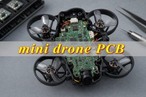
A compact FPV drone often benefits from an AIO board that combines flight control, ESC, and power distribution. The main engineering focus is high-current routing, compact thermal design, clean sensor placement, and durable solder joints.
A camera drone often uses a rigid PCB for the main controller and flexible or rigid-flex boards for the camera and gimbal. This helps reduce cable bulk and supports motion between the body and camera system.
An agricultural drone usually needs stronger power boards, robust connectors, moisture protection, and careful thermal design. The board may look simple, but current load and field operation make reliability critical.
An industrial inspection drone may use multilayer PCB, controlled impedance communication boards, and rigid-flex interconnects. In this case, stable signal transmission and long-term vibration resistance often matter more than the lowest unit cost.
Frequently Asked Questions About Circuit Boards Used in Drones
Q1: What circuit board is the brain of a drone?
The flight controller PCB is usually called the brain of a drone. It processes sensor data from the IMU, barometer, GPS, receiver, and other modules, then sends control commands to the ESCs. A stable flight controller layout needs clean power, low noise, good grounding, and careful sensor placement.
Q2: What is the difference between a flight controller PCB and an ESC PCB?
A flight controller PCB calculates flight attitude and control commands, while an ESC PCB drives the motors. The flight controller handles logic and sensing. The ESC handles high-current switching, MOSFET control, and motor output. Both boards must work together for stable and responsive flight.
Q3: Do drones use rigid PCB or flexible PCB?
Drones can use both. Rigid PCB is common in flight controllers, ESCs, PDBs, and receiver boards. Flexible PCB is common in camera modules, gimbals, foldable arms, and tight spaces. Rigid-flex PCB combines both structures and is often selected when vibration resistance and compact assembly are important.
Q4: Why do some drones use rigid-flex PCBs?
Rigid-flex PCBs reduce cables and connectors, which helps save space and improve vibration resistance. They are useful in compact camera drones, foldable UAVs, and industrial drones with complex mechanical layouts. The main trade-off is higher manufacturing cost and stricter design control during stack-up and bend area planning.
Q5: What PCB material is best for drones?
There is no single best material for every drone. Standard FR4 works well for many control and sensor boards. High-Tg FR4 is better for warmer or denser boards. Polyimide is used for flex circuits. RF laminates support communication modules, while metal core or thicker copper structures help power and thermal boards.
Q6: How many layers does a drone PCB need?
Simple drone boards may use 2 layers, but many flight controllers and ESC boards use 4 layers or more. Compact integrated boards, HDI designs, and advanced camera or RF modules may need 6 layers, 8 layers, or higher. Layer count depends on routing density, power integrity, EMI control, and board size.
Q7: What causes drone PCB overheating?
Drone PCB overheating often comes from narrow high-current traces, poor MOSFET layout, insufficient copper area, weak thermal vias, heavy motor load, or poor airflow. ESC boards and power boards are more sensitive to this problem. Good copper planning, thermal review, and proper component spacing help reduce heat concentration.
Q8: Can one PCB control the entire drone?
Some small drones use AIO boards that integrate flight control, ESC, power distribution, receiver, and video functions. This saves space and weight. Larger or higher-reliability drones often separate these functions into several boards. Separate boards can improve serviceability, thermal management, and modular testing.
Q9: What should buyers send when requesting a drone PCB quote?
Buyers should send Gerber files, drill files, BOM, pick-and-place files, stack-up requirements, copper weight, surface finish, quantity, test requirements, and application details. For drone boards, it is also helpful to share motor current, battery voltage, vibration level, RF requirements, and operating environment.
Q10: Are HDI PCBs useful in drones?
HDI PCBs are useful when the drone needs compact routing, fine-pitch components, small board size, and dense signal connections. They are common in mini flight controllers, camera modules, AI vision boards, and advanced communication modules. HDI improves density, but it requires tighter manufacturing control and higher cost planning.
Q11: How can drone PCB vibration failures be reduced?
Vibration failures can be reduced through stronger mounting design, proper connector selection, balanced component placement, adhesive support for heavy parts, flex or rigid-flex interconnects, and careful solder joint inspection. The PCB should also avoid placing sensitive sensors near strong vibration or noisy switching circuits.
Q12: What quality tests are important for drone PCBs?
Important tests include electrical testing, AOI, impedance testing when required, solderability check, plating inspection, X-ray for hidden solder joints, first article inspection, and functional testing for assembled boards. For rigid-flex or high-current drone boards, bend area review, thermal review, and assembly process control are also important.
Q13: Is a thicker copper PCB always better for drone power boards?
Thicker copper can improve current handling and heat spreading, but it also increases weight, cost, and manufacturing difficulty. For drone power boards, copper thickness should match actual current, board size, thermal path, and layout structure. A balanced design is better than simply choosing the thickest copper.
Q14: How do I choose a supplier for custom drone PCBs?
Choose a supplier with experience in multilayer PCB, rigid-flex PCB, high-current PCB, impedance control, PCBA assembly, and quality inspection. A good supplier should review manufacturability before production, confirm material and stack-up, support testing, and communicate clearly about risks, tolerances, and delivery from prototype to volume production.
Final Thoughts on Drone PCB Selection
The best drone PCB choice depends on the drone’s mission, size, current load, signal speed, operating environment, and production plan. Flight controller boards, ESC boards, PDBs, sensor boards, RF boards, camera boards, BMS boards, rigid-flex PCBs, and HDI PCBs all play different roles in UAV performance.
For engineering teams, the safest path is to define electrical, mechanical, thermal, and environmental requirements before PCB fabrication. For purchasing teams, the best procurement result comes from complete files, clear standards, realistic delivery planning, and a supplier that can support both prototype development and batch production.
If you need drone PCB fabrication, UAV PCBA assembly, rigid-flex drone PCB, HDI drone PCB, RF PCB, high-current ESC PCB, or custom drone electronics manufacturing, EBest Circuit can support your project from sample development to mass production. Contact our engineering team at sales@bestpcbs.com for technical review and quotation support.