PCB manufacturing PCB manufacturing
Home > Blog

design rule check

PCB Design Constraints That Prevent Fabrication Rework
Friday, August 14th, 2026

PCB design constraints turn electrical, mechanical, fabrication, and assembly requirements into limits that the layout team can apply and check before release. Well-defined PCB layout constraints also give the designer, buyer, and manufacturer the same reference when a stackup or process decision changes. The objective is not to use the smallest values a supplier advertises. It is to create a buildable rule set for the actual materials, copper weight, stackup, board geometry, component package, and production volume.

pcb design constraints
PCB design constraints reviewed before fabrication release.

What Are PCB Design Constraints?

PCB design constraints are measurable rules that control how a board is placed, routed, fabricated, and assembled. They connect product requirements to the physical PCB files that a manufacturer receives.

A constraint may define a minimum clearance, an allowed trace-width range, a finished-hole requirement, a differential-pair geometry, a component keepout, or a maximum board dimension. Some constraints protect electrical performance. Others prevent fabrication or assembly defects. Many affect both.

The costly mistake is treating all constraints as software defaults. A design-rule file can confirm that the layout follows the values entered into the ECAD tool, but it cannot prove those values match the selected PCB process. Before release, the project team should connect every critical rule to one of three sources:

  • An electrical or product requirement approved by the customer
  • A mechanical or assembly requirement from the released design
  • A fabrication capability or stackup confirmed by the PCB supplier

This distinction keeps responsibility clear. The customer owns circuit function, component selection, electrical targets, safety and EMC decisions, and the approved design files. The manufacturer confirms whether the released geometry can be produced consistently within the quoted process.

Types of PCB Design Constraints

Missing one constraint category can create a failure outside the area the designer checked. Effective constraint management therefore connects electrical, mechanical, fabrication, assembly, and documentation limits instead of reviewing each group in isolation. A trace may satisfy current requirements but violate fabrication spacing. A component may fit the PCB outline but block an enclosure wall or prevent automated assembly inspection.

The main constraint groups are:

  • Physical constraints: Board outline, thickness, cutouts, mounting holes, component height, keepout areas, and connector locations
  • Fabrication constraints: Trace and space, drill size, annular ring, copper-to-edge clearance, solder mask features, copper weight, layer count, and material choices
  • Electrical constraints: Controlled impedance, net length, differential-pair geometry, clearance for the applied voltage, current capacity, return paths, and sensitive-net separation
  • Assembly constraints: Component spacing, orientation, polarity, pad geometry, fiducials, tooling clearance, rework access, and inspection visibility
  • Documentation constraints: Stackup revision, impedance table, drill information, drawing notes, Gerber or ODB++ revision, BOM revision, and approved exceptions

These groups should not be managed independently. Changing copper weight may affect trace geometry. Changing the stackup may affect impedance. Moving a connector may affect both mechanical fit and assembly access. A release review should therefore check the complete constraint set against one controlled file revision.

PCB Design Rules That Match Fabrication Capability

Generic PCB design rules can prevent obvious layout errors, but they do not automatically match a particular supplier, material system, copper construction, or production target. Using an aggressive default may produce a board that is technically possible but harder to yield consistently. Using an unnecessarily conservative rule may increase size, layer count, or cost.

Before routing, ask the intended manufacturer to confirm the relevant capability for the proposed construction. The review should cover the values that materially affect the quote and build, including:

  • Finished copper weight and the trace/space that applies after plating and etching
  • Minimum finished hole and the required pad or annular ring
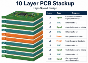
  • Layer count, board thickness, material family, and proposed stackup
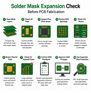
  • Solder mask clearance, solder mask dam expectations, and exposed-copper features
  • Board-edge, slot, routing, scoring, and panelization limitations
  • Controlled-impedance requirements and the data needed for calculation
  • Special processes such as via filling, capped vias, sequential lamination, heavy copper, or rigid-flex construction

Do not copy one supplier’s smallest published number into every net class. Confirm which values are standard, which require a special process, and which should be avoided for a stable production release. The output should be an approved rule set or capability record that the designer can reference when running the final checks.

PCB Trace Width and Spacing Limits

An incorrect trace-width or spacing rule can lead to open circuits, shorts, overheating, impedance deviation, or a quotation that changes after CAM review. The correct value depends on more than a generic minimum.

Trace width may be controlled by current, allowed temperature rise, copper thickness, voltage drop, impedance, and manufacturability. Spacing may be controlled by voltage, safety requirements, signal coupling, copper weight, etching tolerance, and the selected fabrication class.

For release, separate these decisions instead of applying one global rule:

  • Use electrical analysis to define current-carrying and voltage-clearance needs.
  • Use the approved stackup to define impedance-related geometry.
  • Use supplier capability to confirm manufacturable trace and spacing limits for the actual copper construction.
  • Use net classes to keep power, high-speed, sensitive analog, and ordinary signals under the correct rules.
  • Record any intentional exception and obtain approval before fabrication.

The manufacturer can review whether the geometry fits the quoted process, but it should not invent the product’s current, voltage, timing, safety, or signal-integrity requirements. Those inputs must come from the customer engineering team.

Via, Hole, and Pad Constraints

Vias and holes often pass a visual layout check while still creating fabrication or reliability risk. Problems may appear as insufficient annular ring, an impractical aspect ratio, copper breakout, plating difficulty, solder loss through via-in-pad features, or mechanical interference around mounting holes.

The released data should distinguish plated through holes, non-plated holes, blind or buried vias, microvias, filled vias, capped vias, and mechanical slots. For each critical feature, confirm:

  • Finished hole size rather than drill-tool size alone
  • Pad diameter and required annular ring
  • Hole-to-copper and hole-to-board-edge clearance
  • Board thickness and the resulting via aspect-ratio demand
  • Whether via filling, plugging, capping, or tenting is required
  • Whether via-in-pad features affect soldering or component coplanarity
  • Whether mounting hardware needs copper, mask, or component keepouts

A supplier may propose a larger pad, different drill, or alternative via structure when the original geometry is risky. The customer should approve the change because it may affect routing density, impedance, thermal behavior, component escape, and the controlled design revision.

pcb design constraints
Via, hole, and pad constraints checked against manufacturing capability.

Impedance Constraints and Signal Integrity Risks

An impedance note such as “50 ohms” is not a complete manufacturing instruction. The target depends on whether the structure is single-ended or differential, which layers are used, what tolerance is acceptable, and which reference planes, materials, and finished copper values apply.

Before requesting controlled impedance, provide a controlled impedance table or drawing that identifies:

  • Target impedance and allowed tolerance
  • Relevant nets or impedance classes
  • Signal layer and reference layer
  • Preferred trace width and spacing, if electrically fixed
  • Stackup or material restrictions that cannot be changed
  • Coupon and test-report expectations

The PCB manufacturer can calculate a manufacturable geometry for an agreed stackup and can coordinate impedance testing when specified. The customer remains responsible for the electrical target, topology, timing, return-path strategy, simulation assumptions, and final signal-integrity acceptance.

This boundary prevents a common late-stage conflict: the designer fixes a trace width before the production stackup is confirmed, while the supplier later needs a different geometry to reach the target. Align the stackup and impedance model before final routing whenever the design schedule allows.

Component Placement Constraints for Assembly

Components can be electrically correct and still create assembly loss. Parts placed too close to the board edge, tall components, connectors, tooling areas, test points, heat sources, or each other may interfere with printing, placement, soldering, inspection, depanelization, enclosure fit, or rework.

The placement review should include:

  • Component-to-board-edge and component-to-cutout clearance
  • Connector position, insertion direction, and mating access
  • Polarity and orientation consistency
  • Spacing around tall, heavy, heat-sensitive, or hand-soldered components
  • Fiducial, tooling-hole, rail, and panelization needs
  • Access for automated optical inspection, test probes, and rework tools
  • Pad and paste decisions for thermal pads, fine-pitch parts, BGAs, and bottom-terminated components
  • Component-height restrictions and mechanical keepout areas

Assembly constraints should be checked against the PCB, BOM, centroid data, assembly drawing, enclosure information, and any agreed panel requirement. EBest Circuit (Best Technology) can review PCB manufacturability and assembly-related risks within the supplied data, support PCB fabrication, component sourcing, PCBA, inspection, and coordinated testing. The customer must approve component choice, circuit function, mechanical envelope, and released files.

pcb design constraints
Component placement constraints reviewed for PCB assembly access and inspection.

PCB Design Rule Check Before Release

A clean PCB design rule check is useful evidence, but it only proves compliance with the rules configured in the software. It does not prove that the rules are complete, that the stackup is current, or that the fabrication drawing and layout use the same revision.

Before release, combine automated DRC with a controlled handoff review:

  • Confirm that the rule set matches the selected supplier capability and approved stackup.
  • Resolve or formally waive every critical violation.
  • Compare the PCB outline, cutouts, mounting holes, and connector locations with the mechanical source.
  • Verify that impedance classes, drill information, copper weight, and drawing notes agree.
  • Check that the BOM, centroid file, assembly drawing, and PCB data share one revision.
  • Remove obsolete files from the release package.
  • Identify intentional deviations instead of expecting CAM engineers to guess.

Send the supplier the complete release package before expecting a production-ready quotation. If an important decision is still open, label it clearly and request a DFM response against that specific point.

A PCB Design Constraints Example for DFM Review

Consider a compact multilayer controller board with controlled-impedance signals, a fine-pitch component, several mounting holes, and connectors positioned against an enclosure opening. The layout team completes routing using an internal rule template and sends Gerbers for quotation.

During review, the proposed stackup requires a different impedance geometry, one via structure is difficult for the selected board thickness, copper sits too close to a routed slot, and a connector body reduces access around a nearby component. These are among the most common PCB design mistakes that escape a rule check built around incomplete supplier or assembly inputs. None of these issues means the product concept is wrong, but each can delay the release or force a revision.

A controlled DFM response would separate the decisions:

  • The supplier proposes a manufacturable stackup and impedance geometry.
  • The designer confirms whether the revised geometry still meets electrical requirements.
  • The supplier identifies the via and copper-clearance risks.
  • The customer approves layout changes and updates the controlled PCB revision.
  • The assembly review checks connector access, placement clearance, polarity, and inspection needs.
  • The final package is reissued with aligned fabrication, assembly, drill, and BOM data.

The avoided loss is not merely one CAM question. It is the accumulation of quote revisions, purchasing delays, unapproved shop-floor changes, and uncertainty about which files represent the product. Clear PCB design constraints move those decisions before production.

FAQs About PCB Design Constraints

When should PCB design constraints be defined?

Define product and electrical requirements before layout, then align fabrication and assembly limits with the intended supplier before final routing. Recheck them whenever the stackup, copper weight, board thickness, component package, or mechanical design changes.

Are PCB design rules and PCB design constraints the same?

They are closely related, but a design rule is often a specific check implemented in software, while a constraint can also be an electrical, mechanical, fabrication, assembly, or documentation limit that requires engineering review.

Does a clean DRC mean the PCB is ready for fabrication?

No. A clean DRC only confirms that the layout follows the configured rules. The team must still verify supplier capability, stackup, impedance data, drills, outline, drawings, assembly files, and revision consistency.

Who should approve a change suggested during PCB DFM?

The supplier can explain the manufacturing risk and propose an alternative. The customer should approve changes that may affect electrical performance, mechanical fit, component placement, reliability, or the released design revision.

What files help a supplier review PCB design constraints?

Provide the controlled PCB fabrication data, fabrication drawing, drill information, approved stackup or stackup requirements, impedance table when applicable, BOM, centroid data, assembly drawing, mechanical information, and a list of approved exceptions. To discuss a project with EBest Circuit (Best Technology), contact sales@bestpcbs.com with the current release package and the constraints that still need confirmation.


You may also like

What is Design Rule Check (DRC) in PCB? Types of Deisgn Rule Checking
Monday, April 13th, 2026

What Is Design Rule Check (DRC)?

Design Rule Check (DRC) is a software-driven process that verifies PCB layout parameters (trace width, spacing, clearance, pad size, via dimensions, etc.) against pre-defined manufacturing rules. It acts as a “safety net” to catch geometric defects—like shorts, open circuits, or undersized features—before you send Gerber files to production. DRC matters because even a small violation (e.g., 2mil insufficient clearance) can render an entire batch of PCBs unusable, leading to rework costs that are 3–10× higher than fixing issues during design.

For mass production, DRC is non-negotiable: it ensures consistency across your design, aligns with your manufacturer’s capabilities, and reduces the risk of failed prototypes or field failures. In short, DRC saves time, money, and frustration by catching problems early, when they’re cheapest to fix.

What Is Design Rule Check (DRC)?

Design Rule Check (DRC)

Types of Design Rule Checking

The core check items in DRC are the geometric parameters that directly impact PCB manufacturability and performance. As an experienced PCB manufacturer, we prioritize these 7 key check categories—they cover 95% of common DRC violations and align with industry standards (IPC-2221, IPC-6012). Each check ensures your layout is compatible with your manufacturer’s equipment and materials, avoiding costly rework. Below are the core DRC check items, with brief explanations of why they matter:

  • Trace Width & Spacing: Ensures traces can carry current without overheating and prevents short circuits between adjacent traces. Minimum values depend on current load and manufacturing process.
  • Clearance: The minimum distance between conductive features (traces, pads, vias) to prevent arcing, especially in high-voltage designs. Clearance requirements increase with voltage.
  • Pad Size & Annular Ring: Ensures pads are large enough for soldering and vias have sufficient copper around the drill hole (annular ring) to avoid delamination or breakage.
  • Via Dimensions: Checks drill size, annular ring, and via placement to ensure compatibility with drilling equipment and signal integrity.
  • Component Placement: Verifies components are not overlapping, are placed within keepout zones, and have enough space for soldering and assembly.
  • Silk Screen Overlap: Prevents silk screen ink from covering pads or vias, which would interfere with soldering.
  • Copper Pour & Thermal Relief: Ensures copper pours are properly connected (no unconnected copper) and thermal reliefs are sized to balance heat dissipation and solderability.
What Is Design Rule Check (DRC)?

How to Set Up DRC Rules Matching PCB Manufacturer Capabilities?

Setting up DRC rules that match your PCB manufacturer’s capabilities is critical—rules that are too strict will slow down your design, while rules that are too loose will lead to fabrication failures. Below is a step-by-step guide to setting up DRC rules correctly, based on our experience working with 20+ PCB manufacturers:

1. Request the Manufacturer’s Rule Sheet: Every reputable PCB manufacturer provides a DRC rule sheet with their minimum capabilities (e.g., min trace/space, via size). This is your starting point—never guess or use generic rules.

2. Input Core Parameters into Your PCB Design Software: In tools like Altium, KiCad, or Eagle, navigate to the DRC settings and input the manufacturer’s min trace width, spacing, clearance, pad size, and via dimensions. Use the table below as a reference for standard capabilities.

3. Adjust for Design Specifics: If your design includes high voltage (≄2kV), high frequency (≄1GHz), or high current (≄2A), increase relevant rules (e.g., wider traces for high current, larger clearance for high voltage).

4. Set Up Zone Rules: For mixed-signal or high-voltage designs, create zone rules (e.g., a high-voltage zone with 20mil clearance) to apply different rules to specific areas of the PCB.

5. Enable Real-Time & Batch Checks: Turn on real-time DRC to catch violations as you route, and set up batch DRC to run a full check before finalizing your design.

6. Test with a Sample Layout: Run a small test layout (e.g., a simple power supply circuit) through DRC to ensure rules are working correctly—this avoids costly mistakes in your main design.

PCB ProcessMin Trace/SpaceMin Via (Drill/Ring)Min Clearance
Standard FR-4 (1–6L)6/6mil0.3mm/8mil8mil
High-TG Thin Core4/4mil0.25mm/7mil6mil
High-Voltage (≄2kV)8/8mil0.3mm/10mil20–30mil

What Are the Most Common DRC Violations in PCB Design?

Even experienced PCB engineers encounter DRC violations—but the same 5 violations account for 80% of all issues. Knowing these common violations, their root causes, and quick fixes will save you hours of troubleshooting. From our experience, the most frequent DRC violations are related to clearance, trace width, pad size, via dimensions, and component placement. Below is a detailed breakdown of each, including why they happen and how to fix them fast:

DRC Violation TypeRoot CauseQuick FixPreventive Measure
Insufficient ClearanceUsing generic clearance rules instead of manufacturer specs; high-voltage areas not marked; accidental trace overlapWiden spacing to match manufacturer’s min (8mil for standard PCBs); apply zone rules for high-voltage areas (20–30mil); move overlapping traces apartSet up zone rules early; use real-time DRC during routing
Trace Too NarrowBelow manufacturer’s min trace width; undersizing for current load; tight routing in dense areasWiden trace to ≄4–6mil (standard) or ≄8–12mil (high current); reroute dense areas to avoid narrow tracesCalculate trace width based on current load (use online calculators); leave extra space in dense areas
Pad Annular Ring Too SmallPad diameter undersized for via drill; incorrect pad-via alignmentEnlarge pad to ≄18–22mil for 0.3–0.4mm drill; realign pad and via to ensure full annular ringUse manufacturer-provided pad-via templates; double-check pad dimensions before routing
Via Too SmallDrill/annular ring below manufacturer’s process limits; using microvias without confirming capabilityUse ≄0.2mm drill + ≄8mil ring for standard PCBs; switch to larger vias if microvias are not supportedConfirm via capabilities with your manufacturer; avoid microvias for low-cost PCBs
Component CollisionPoor component placement; ignoring keepout zones; using incorrect component footprintsMove colliding components apart; adjust keepout zones; replace incorrect footprints with manufacturer-approved onesUse 3D view to check placement; follow component datasheet footprint guidelines

How to Quickly Fix DRC Errors Step by Step?

Fixing DRC errors doesn’t have to be a tedious process—with a systematic approach, you can resolve even complex violations in minutes. The key is to prioritize critical errors first (e.g., shorts, open circuits) and use your design software’s built-in tools to speed up troubleshooting.

1. Run a Full Batch DRC: First, run a complete batch DRC to generate a detailed error report. Most PCB software (Altium, KiCad) will list errors by type, location, and severity—this helps you prioritize.

2. Prioritize Critical Errors: Focus on critical errors first: shorts (between traces/pads), open circuits (unconnected copper), and violations that will prevent fabrication (e.g., undersized vias). Non-critical errors (e.g., minor silk overlap) can wait.

3. Use Jump-to-Error Tools: Use your software’s “jump to error” feature to navigate directly to the violation—this saves time vs. searching manually. For example, in Altium, right-click an error and select “Jump to.”

4. Apply Quick Fixes for Common Violations: Use the fixes from the table above for common errors (e.g., widen traces, adjust clearance). For multiple identical errors (e.g., 10 instances of insufficient clearance), use batch edit tools to fix them all at once.

5. Verify Fixes in Real-Time: After fixing an error, enable real-time DRC to confirm it’s resolved. This prevents “fixing” one error and creating another (e.g., widening a trace and causing a new clearance violation).

6. Run a Final Batch DRC: Once all errors are fixed, run another full batch DRC to ensure no violations were missed. If errors remain, repeat the process—focus on root causes (e.g., incorrect rules) instead of band-aid fixes.

Online DRC vs Batch DRC: Which Is Better for Your Design?

Online DRC and Batch DRC are two common check modes, each with pros and cons—choosing the right one depends on your design stage and goals. Online DRC runs in real-time as you route, catching errors immediately, while Batch DRC runs a full check on your entire layout, ideal for final verification. Below is a detailed comparison to help you decide when to use each:

Check ModeSpeedAccuracyBest Use CaseProsCons
Online DRCReal-time (instant)Medium (catches most common errors)Routing, component placement, and initial design stagesCatches errors early; saves time on later troubleshooting; easy to fix mistakes immediatelyMay miss rare or complex violations; can slow down software on large designs
Batch DRCSlower (depends on design size; 1–5 minutes for most PCBs)Full (catches all violations, including rare ones)Final sign-off before generating Gerber/ODB++ files; post-routing verificationComprehensive; generates detailed error reports; ensures no violations are missedTakes time to run; errors may be harder to fix if left until the end

Pro Tip: Use online DRC during routing to catch mistakes as you go, then run a batch DRC every 2–3 hours to ensure no errors slip through. For final verification, run batch DRC twice—once after fixing errors, and once before sending files to your manufacturer.

High-Voltage PCB DRC Rules

High-voltage PCBs require larger clearances to prevent arcing and insulation breakdown. The IPC-2221 standard provides guidelines, but you should also consult your manufacturer’s capabilities. Key parameters:

  • Clearance: 20–30mil for 2–5kV; 50–100mil for 5–10kV. Increase by 10mil for every additional 1kV above 10kV.
  • Trace Width: ≄8–12mil to handle current and reduce resistance. For currents ≄5A, use ≄15mil traces.
  • Via Dimensions: ≄0.3mm drill + ≄10mil annular ring. Avoid microvias—use through-hole vias for better insulation.
  • Insulation Layer: Use high-TG FR-4 (≄170°C) or polyimide for better insulation. Ensure insulation thickness is ≄0.2mm per kV.
High-Voltage PCB DRC Rules

High-Frequency PCB DRC Rules

High-frequency PCBs require tight control over trace geometry to minimize signal loss and crosstalk. Key parameters are based on impedance matching (50Ω, 75Ω) and signal integrity:

  • Trace Width & Spacing: Match trace width to impedance (e.g., 50Ω impedance = 5–7mil trace on 0.062” FR-4). Spacing between high-frequency traces should be ≄2× trace width to reduce crosstalk.
  • Clearance to Ground Planes: Ensure high-frequency traces are 0.020–0.030” above ground planes to maintain impedance.
  • Via Placement: Minimize via count—each via adds parasitic capacitance and inductance. Use blind/buried vias for dense designs, and keep vias at least 50mil apart from high-frequency traces.
  • Component Placement: Place high-frequency components (e.g., oscillators, amplifiers) close together to minimize trace length. Avoid placing them near power components to reduce interference.

How to Generate & Read DRC Reports Effectively?

DRC reports are critical for troubleshooting and documentation—they provide a detailed overview of all violations, their locations, and severity. Generating a clear, actionable DRC report saves time and ensures you don’t miss errors, while reading the report effectively helps you prioritize fixes. At EBest Circuit, we use these steps to generate and read DRC reports like a pro:

How to Generate a DRC Report?

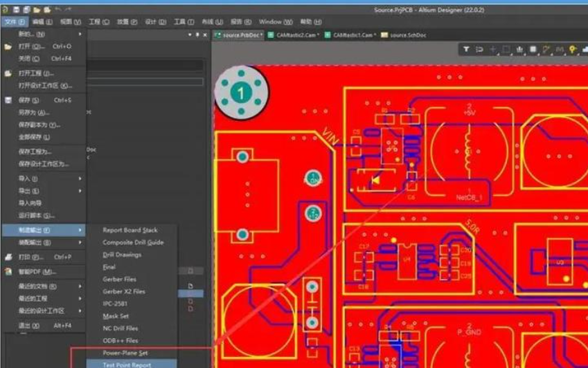
1. Run a Full Batch DRC: In your PCB design software, run a complete batch DRC (e.g., Altium: Tools → Design Rule Check; KiCad: Tools → DRC).

2. Customize Report Settings: Select the information to include: error type, location (X/Y coordinates), severity, and description. Most software allows you to filter by error type (e.g., only clearance violations).

3. Export the Report: Export the report to a format that’s easy to share (PDF, CSV, or HTML). PDF is best for documentation, while CSV is useful for sorting and filtering errors.

How to Read a DRC Report Effectively?

1. Sort by Severity: Most reports allow you to sort errors by severity (critical, warning, info). Focus on critical errors first—these are the ones that will prevent fabrication or cause failures.

2. Filter by Error Type: Group errors by type (e.g., clearance, trace width) to fix similar errors in batches. This saves time vs. fixing errors one by one.

3. Use Location Data: Use the X/Y coordinates in the report to jump directly to the violation in your design software. This eliminates manual searching.

4. Document Fixes: Keep a log of which errors were fixed, how they were fixed, and who fixed them. This is useful for future designs and quality control.

Pro Tip: For large designs, generate a “before and after” DRC report—one before fixing errors, and one after. This confirms all violations were resolved and provides documentation for your manufacturer.

DRC vs ERC vs LVS: What’s the Difference?

DRC, ERC (Electrical Rule Check), and LVS (Layout vs Schematic) are three critical verification processes in PCB design—but they serve different purposes. Many engineers confuse them, leading to incomplete verification and costly mistakes. Below is a clear comparison of DRC, ERC, and LVS, including their purpose, what they check, and when to use each:

Verification TypePurposeWhat It ChecksWhen to UseKey Benefit
Design Rule Check (DRC)Ensure PCB layout is manufacturableGeometric parameters: trace width, spacing, clearance, pad size, via dimensions, component placementDuring routing, post-routing, and before Gerber generationPrevents fabrication defects and rework
Electrical Rule Check (ERC)Ensure PCB has no electrical errorsElectrical connections: unconnected nets, short circuits, incorrect pin connections, missing pull-up/down resistorsAfter schematic design and before layoutCatches electrical mistakes that DRC misses (e.g., unconnected power nets)
Layout vs Schematic (LVS)Ensure layout matches the schematicNet connections: verify that every trace in the layout connects to the correct component pins as per the schematicAfter layout and DRC, before final sign-offPrevents functional failures (e.g., a trace connected to the wrong pin)

Critical Note: DRC alone is not enough—always run ERC before layout and LVS after layout to ensure your PCB is both manufacturable and functional. We’ve seen designs pass DRC but fail LVS, leading to non-functional prototypes and costly rework.

FAQs

Q: What is Design Rule Check in PCB?

A: Design Rule Check (DRC) is a software-driven verification process that validates PCB layout parameters (trace width, spacing, clearance, pad size, via dimensions, etc.) against pre-defined manufacturing rules. It catches geometric defects early, ensuring your PCB is fabricable and free of costly errors.

Q: What happens if you ignore DRC violations?

A: Ignoring DRC violations leads to fabrication failures (e.g., shorts, open circuits), failed prototypes, and rework costs that are 3–10× higher than fixing issues during design. In worst cases, it can lead to field failures, product recalls, and safety hazards (especially for high-voltage PCBs).

Q: How to set up DRC rules for PCB design?

A: Start with your manufacturer’s DRC rule sheet (min trace/space, via size, etc.), input these parameters into your PCB design software, adjust for your design’s specific needs (e.g., high voltage, high frequency), set up zone rules for mixed-signal designs, and test with a sample layout.

Q: What are typical DRC errors?

A: The most common DRC errors are insufficient clearance, trace too narrow, pad annular ring too small, via too small, component collision, silk screen overlap, and unconnected copper. These errors account for 80% of all DRC violations.

Q: Can DRC find all PCB manufacturing issues?

A: No—DRC only catches geometric violations. It does not find schematic-layout mismatch (that’s LVS) or electrical issues (that’s ERC). To ensure a fully manufacturable, functional PCB, you need to run DRC, ERC, and LVS.

Q: How often should I run DRC in PCB design?

A: Run real-time DRC during routing to catch errors as you go, and run a full batch DRC every 2–3 hours to ensure no errors slip through. For final verification, run batch DRC twice—once after fixing errors, and once before sending files to your manufacturer.

Q: How to fix DRC errors in dense PCB layouts?

A: For dense layouts, use smaller vias (if your manufacturer supports them), reroute traces to use available space, apply zone rules to prioritize critical traces, and use batch edit tools to fix multiple identical errors. If necessary, consider a multi-layer PCB to increase routing space.

You may also like