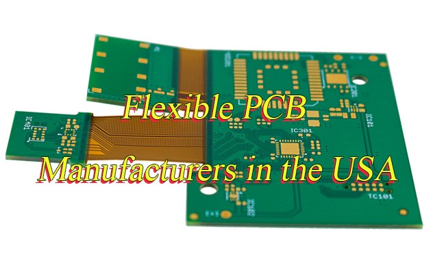
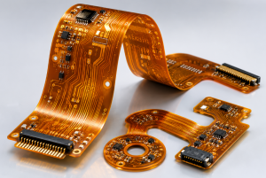
A fabric circuit board carries electrical connections on or within a textile, rather than relying only on copper laminated to a conventional board. Conductive yarns, patterned conductive layers and small electronic modules can work together in one soft assembly. The attraction is comfort and integration with clothing; the challenge is keeping the electrical path predictable while the textile bends, stretches and gets handled.
Do not choose it simply because a project must bend. A conventional flexible PCB may already solve that requirement. Choose textile conductors when the fabric itself needs to carry sensing, switching or distributed connections—and check resistance, joints and cleaning conditions before committing the architecture.
What Is a Fabric Circuit Board?
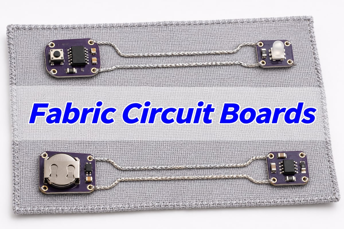
A fabric circuit board combines a textile carrier with deliberately defined conductive paths and electrical connection points. “Fabric” describes the carrier or interconnection system; it does not mean ordinary cloth is conductive. The conductive material must be added, integrated or patterned.
Common approaches include sewing conductive thread, weaving conductive yarn, printing a conductive pattern on a suitable textile or film, and attaching conventional circuit islands. These approaches are not interchangeable manufacturing recipes. A yarn network follows textile construction; a printed layer depends on its substrate and ink system; a small flex PCB retains its own copper-and-dielectric structure.
Fraunhofer IZM’s TexPCB research demonstrates textile-integrated circuit technology. It establishes that textile circuit architectures exist, not that any garment, conductive cloth or PCB factory automatically has the same capabilities. Ask what the proposed construction actually contains before comparing specifications.
Textile Circuit Board vs Flexible PCB
Use a textile circuit where textile integration is part of the function; use a conventional flex where controlled electronic interconnection is the main task. A hybrid can use each where it is strongest.
| Architecture | Choose it when / verify |
| Conductive textile or sewn thread | Use for distributed contacts, soft controls or connections following a garment. Verify path resistance and contact stability under the actual motion and cleaning conditions. |
| Conventional flexible PCB | Use for compact copper routing and assembled components. Verify the approved flex construction and bending conditions; flexibility does not imply free stretching. |
| Hybrid textile plus PCB islands | Keep precision electronics on a conventional board and textile electrodes or controls elsewhere. Verify the textile-to-board connection and mechanical load transfer, not only each material separately. |
For a sleeve-mounted button, a short sewn connection may be reasonable. For a fine-pitch processor and its local decoupling, retain a conventional PCB island. If several milliamps of supply current must travel a long distance, calculate the textile path loss before choosing the conductor.
A foldable assembly is not necessarily stretchable. Bending changes curvature; stretching changes the distance between connection points. If the textile stretches but an attached copper flex cannot accommodate that movement, strain concentrates at the transition. Conventional flexible PCB construction and design must therefore be considered separately from textile elasticity.
Conductive Thread Resistance: Budget the Complete Loop
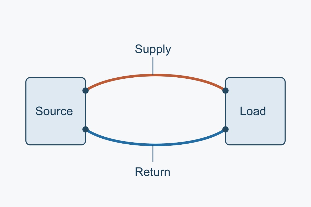
Count both the outward conductor and the return conductor. A conductive thread’s Ω/ft rating is resistance per unit length, not the resistance of a complete finished circuit and not bulk resistivity in Ω·m.
| Named material | Product data and use |
| Adafruit 640, 2-ply stainless conductive thread | Approximately 16 Ω/ft in the description; 0.2 mm thickness and 1.3 Ω/in in technical details. Use the approximate rating for an initial budget, then measure the actual sewn path. |
| Adafruit 641, 3-ply stainless conductive thread | Approximately 10 Ω/ft in the description; 0.25 mm thickness and 0.83 Ω/in in technical details. Lower nominal resistance, with a thicker thread to accommodate mechanically. |
These are product-specific examples from product 640 and product 641, not specifications for all 2-ply or 3-ply yarns. The inch and foot figures are rounded descriptions, not perfectly matching precision measurements. Verify the purchased material and lot rather than treating ply count as an electrical grade.
Use Rloop = rL + Rcontacts and ΔV = IRloop. Here r is resistance per unit length, L is the total conductor length, and the contact term includes the joints in the supply-and-return path.
Consider a teaching example with a regulated 3.3 V source, a load drawing a constant 20 mA, and two 6-inch runs. The total conductor length is 12 inches, or 1 ft. Ignoring contact resistance, the 16 Ω/ft thread loses 0.32 V and leaves 2.98 V at the load. The 10 Ω/ft thread loses 0.20 V and leaves 3.10 V. If the hypothetical load requires at least 3.0 V, the first option already fails that budget, while the second retains only 0.10 V of margin.
That conclusion is conditional: the load must actually behave as assumed. An LED connected directly across a source is not a constant-current load. Battery variation, peak current and connection changes require their own checks. Current guidelines for a thread also do not prove temperature or wearer safety in a finished product.
Fabric Circuit Board Materials and Connections
Choose the carrier, conductor and joining method as one construction. A low-resistance conductor does not rescue an unstable contact, and an electrically good joint may still be too stiff for the textile around it.
For sewn circuits, identify fibre composition, linear resistance and how the thread terminates at the module. For patterned conductive films, obtain the specific material system’s data and process instructions. Do not substitute a generic curing temperature or assume any fabric tolerates a standard PCB reflow profile.
Define which surface touches the body, how adjacent conductors remain separated, and what happens when a loose end moves. Thread tails, folds and a damaged insulation layer can create unintended connections. Inspect both faces and the assembly in its deformed positions—not just flat on the bench.
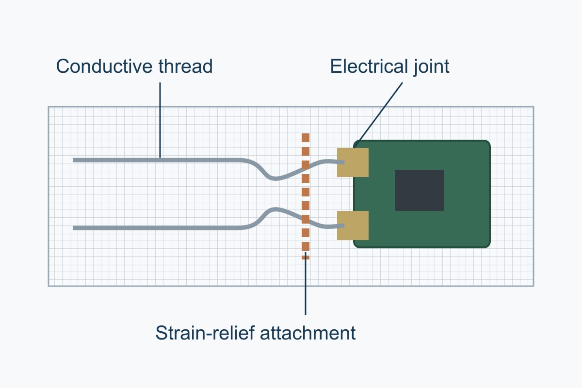
At a module, electrical contact and mechanical attachment are distinct jobs. A robust design gives the thread or contact an intentional electrical interface, while a separate fastening or strain-relief feature carries movement where necessary. Do not assume stainless conductive thread can be soldered like copper wire. Use a joining method supported by the selected materials and validate the finished connection.
E Textile Circuits: Manage Movement at the PCB Edge
The transition from soft textile to a stiff component is often the part that needs the most attention. Pulling on the garment should not repeatedly pull directly on the electrical contact.
Locate the rigid island away from a fold or stretch concentration where the product permits. Provide an appropriate transition, slack or strain-relief arrangement, without creating loose conductive loops that can touch other nets. A zigzag route can accommodate geometry differently from a taut straight run, but its longer path also increases resistance. Calculate its actual conductor length.
Return to the 20 mA example. If the two joints add an assumed total of 1 Ω, the 2-ply loop becomes 17 Ω: its loss is 0.34 V and the load sees 2.96 V. The 3-ply loop becomes 11 Ω: its loss is 0.22 V and the load sees 3.08 V. Even the second option has little room for further degradation against the assumed 3.0 V minimum.
Measure across the complete path at rest and while applying the specified product movement. A stable average can conceal intermittent opens, so monitor continuity or the relevant circuit output during motion as appropriate. If the symptom follows the joint while the thread segment remains stable, improve that transition rather than merely replacing the entire textile conductor.
Detachable Connections: Make the Electronics Removable
A detachable interface can separate a washable textile from electronics that should not enter the wash. It also introduces another contact system to specify and test.
The 2019 fabric circuit board connection study in Sensors examines permanent and detachable interfaces between fabric circuits, sensors and rigid components. Its results apply to its particular construction and test conditions; they are not a universal stretch allowance or washing-life specification.
Define contact orientation, retention, electrical rating, exposed-contact protection and the user’s removal sequence. If the connector can be reversed, a garment label alone may not be adequate error prevention. If several circuits share a connector, identify every net and check that a partly engaged connector does not create an unintended state.
Verify resistance and function before and after the agreed number of mating operations. Record what was removed during cleaning and what remained in the textile. A test on a disconnected fabric panel cannot establish the washability of a version with the battery and controller left attached.
Fabric Circuit Board Washing: Define the Actual Test
“The thread is washable” is not enough to approve a complete electronic textile. The textile, contacts, module attachment, insulation and electronics need an agreed test configuration and functional requirements.
ISO 6330:2021 specifies domestic washing and drying procedures for textile testing. A complete test includes both washing and drying. It does not, by its title alone, certify a wearable electronic product or prescribe a universal number of successful cycles for every application.
Specify the applicable procedure, number of cycles, sample count, removal state, drying process and post-test conditioning. Measure the same defined paths before and after, and perform the functional checks the application requires. Also inspect conductor separation, fraying, delamination and connection damage. Choose acceptance limits from the product’s electrical and mechanical requirements, not an invented percentage.
| Review field | Worked example and decision |
| Electrical budget | Example: 3.3 V source, 20 mA load, 3.0 V minimum gives Rloop,max = 0.3/0.020 = 15 Ω. This limit applies only to these assumptions; include supply/current tolerances and agreed margin in the actual specification. |
| Example post-test result | A hypothetical 17 Ω loop gives a 0.34 V drop and 2.96 V at the load: fails this example budget even if the textile still looks intact. |
| Missing washing conditions | A report says “washed successfully” but omits procedure, drying and module-removal state. Obtain the missing configuration and test record before using it to approve the product. |
Use this worksheet when reviewing a prototype report: enter the actual load requirement first, then check the measured path and test configuration. Small resistance changes near the limit require attention to contact repeatability and instrument uncertainty. Do not turn a rounded measurement into a confident pass.
E Textiles Examples: Match the Circuit to the Job
Applications need different validation because the useful signal and unwanted effects differ. A circuit that works for a soft button may be unsuitable for a precision sensor or distributed power feed.
Clothing-mounted buttons and interactive controls. Put the textile contact where the user presses and keep the controller on a stable island. Preserve intentional presses while rejecting movement-induced connections. Verify the input state during the intended gesture, normal garment movement and release; check for stuck or unintended activations rather than only measuring flat resistance.
Indicator LEDs and low-power accessories. Put light where it is useful, but include the outward and return paths in the supply budget. Use the voltage-drop calculation above with the actual driver and maximum load. Verify voltage at the distant module under the worst relevant load and motion. If the minimum supply requirement is not met, shorten the path, change the conductor or relocate the driver—not just increase source voltage without checking every component.
Textile sensing surfaces. A pressure, contact or movement sensor may deliberately change resistance or another electrical quantity. Separate that intended change from unwanted lead and connector changes. Characterize output against the controlled physical input, then repeat with garment movement and the specified environmental conditions. Do not interpret every resistance change as the sensed event.
Hybrid wearable electronics. Keep processing, local power management and dense interconnections on conventional PCB or flex islands, with textile paths serving suitable remote functions. Validate both the electronic module and its installed textile connections. Medical, heating or other safety-critical applications need their own applicable risk assessment and qualification; this architecture guide is not a substitute.
Fabric Circuit Board FAQs
1. Is ordinary cotton electrically conductive?
Not as a designed circuit conductor. A fabric circuit needs a defined conductive material or attached interconnect. Moisture or contamination causing leakage does not make ordinary cotton a predictable replacement for conductive thread.
2. Can I replace a copper wire with any conductive thread?
No. Check the named thread’s resistance per length, total loop length, joints and load requirement. In the stated 20 mA example, just 1 ft at 16 Ω/ft causes a 0.32 V drop before contact losses.
3. Do more stitches always reduce contact resistance?
No universal rule establishes that. Stitch placement, tension, contact material and movement change the interface. Verify resistance and continuity on the actual joint rather than assuming stitch count alone guarantees a connection.
4. Can two textile traces cross?
Only with a deliberately insulated and validated crossing structure if the nets must remain separate. Check both sides, folded positions and wear. A flat visual gap is not proof that conductors cannot touch in use.
5. Does a removable battery make the garment washable?
Not automatically. Other modules and joints may remain vulnerable. State the complete removal configuration and validate the remaining assembly using the specified washing, drying and functional checks.
6. Can a continuity beep approve the power path?
No. It can help locate an open, but its threshold does not establish acceptable loaded voltage. Measure path resistance and verify voltage at the load using the actual operating conditions.
7. Is a textile circuit suitable for high-speed data?
Do not infer that from low DC resistance. The connection structure, return path, impedance and movement can affect signal quality. Use a qualified interconnect architecture and verify the actual interface rather than treating textile thread as a generic controlled-impedance line.
8. How much power is lost in the conductive thread?
Use P = I²R. At the example’s constant 20 mA, a 16 Ω path dissipates 6.4 mW and a 10 Ω path dissipates 4 mW, excluding contacts. Those electrical-loss calculations do not predict local temperature or establish wearer safety.
Custom Flexible PCBs with Project-Specific Manufacturing Review
Need a conventional flex circuit or assembled PCB island for your wearable design? Send EBest Circuit the board files and interface requirements before committing the textile assembly. A defined PCB/PCBA scope and a project-specific manufacturing review help identify the construction, attachment and assembly inputs that need agreement, without confusing the fabric prototype with the board to be manufactured.
Provide Gerber or ODB++ files, the intended flex region, material and thickness requirements, quantities and delivery target. For assembly, include the BOM and placement data. Describe the connection to the textile and its movement requirements so the relevant manufacturing scope can be checked. Prepare your flex PCB enquiry, or email sales@bestpcbs.com to request a manufacturing review and quotation.