Electronic equipment can remain useful long after one of its circuit boards begins to age or fail. A damaged relay, degraded capacitor, corroded connector, cracked solder joint, or localized PCB defect does not always justify replacing the complete assembly.
Circuit board refurbishing restores an aged, damaged, or failed electronic board to a usable and verified condition. Depending on the board, the work may involve troubleshooting, cleaning, component replacement, solder rework, conductor repair, and functional testing.
It is particularly relevant to industrial electronics, legacy equipment, discontinued assemblies, and high-value boards where direct replacement may be difficult or uneconomical.
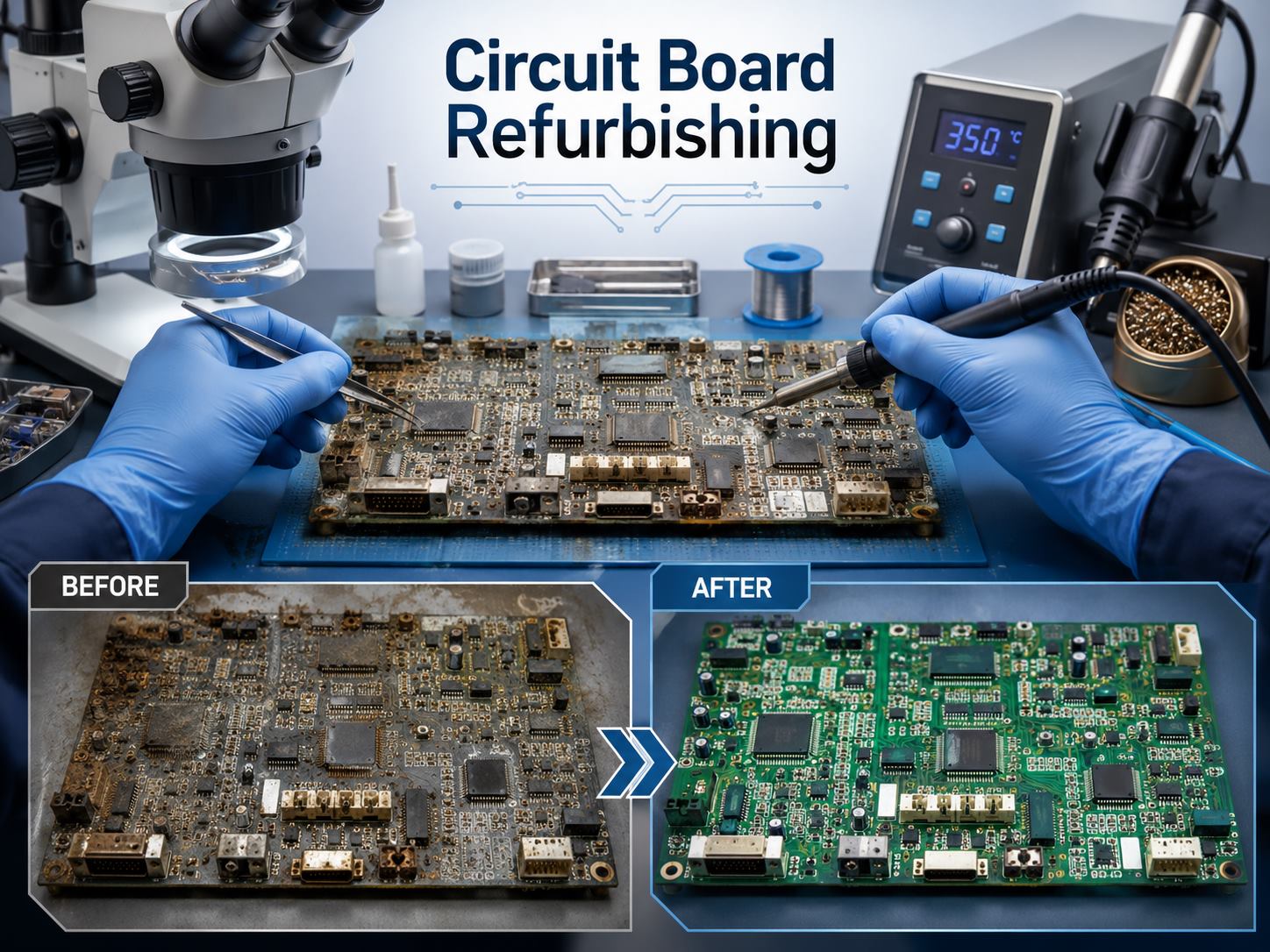
What Is Circuit Board Refurbishing?
Circuit board refurbishing is a broader restoration process than simply replacing one failed part.
Although the term “circuit board” is sometimes used for a bare PCB, refurbishment usually applies to a populated assembly containing components, connectors, solder joints, and interconnections.
Typical work can include:
- replacing failed or degraded components;
- repairing cracked or defective solder joints;
- restoring damaged pads, traces, or vias;
- cleaning corrosion and contamination;
- repairing connectors and contacts;
- removing and replacing damaged conformal coating;
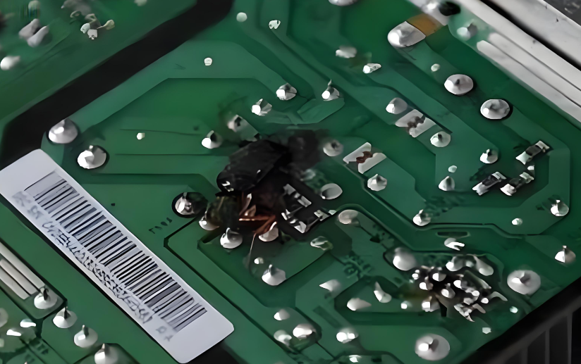
- checking areas affected by overheating;
- testing the board after rework.
The objective is to restore the board to a condition where its required functions can be verified, not to make an old assembly physically identical to a newly manufactured one.
What Is the Difference Between Circuit Board Refurbishing and PCB Repair?
PCB repair normally targets a known fault, while circuit board refurbishing evaluates the board more broadly before returning it to service.
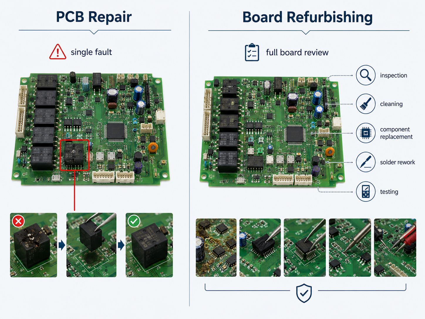
| PCB Repair | Circuit Board Refurbishing |
| Usually starts with a specific fault | May start with failure, age, or deterioration |
| Focuses on the failed area | Looks at the wider board condition |
| Often replaces one defective part | May replace failed and selected aging parts |
| Main goal is fault correction | Main goal is restoring serviceability |
| Testing may focus on the repaired circuit | Testing may cover a wider range of board functions |
For example, replacing a failed relay and checking its output is a repair. If the same board is also inspected for heat damage, deteriorated capacitors, connector corrosion, weak solder joints, and other age-related problems before being functionally tested, the work is closer to refurbishment.
Which Circuit Boards Are Good Candidates for Refurbishing?
Boards are generally worth evaluating when they are expensive, difficult to replace, or installed in equipment that still has useful service life.
Common candidates include:
- industrial control boards;
- PLC and automation electronics;
- motor-drive boards;
- power-control assemblies;
- machine-tool electronics;
- legacy instrumentation;
- discontinued OEM boards;
- proprietary low-volume assemblies;
- equipment with long spare-part lead times.
The best candidates usually have localized faults and a mechanically sound PCB substrate.
Schematics, a BOM, service documentation, firmware information, a known-good board, or an existing test procedure can also make diagnosis much more practical.
What Problems Can Circuit Board Refurbishing Correct?
Refurbishment is most suitable for defects that can be isolated and repaired without rebuilding large portions of the PCB.
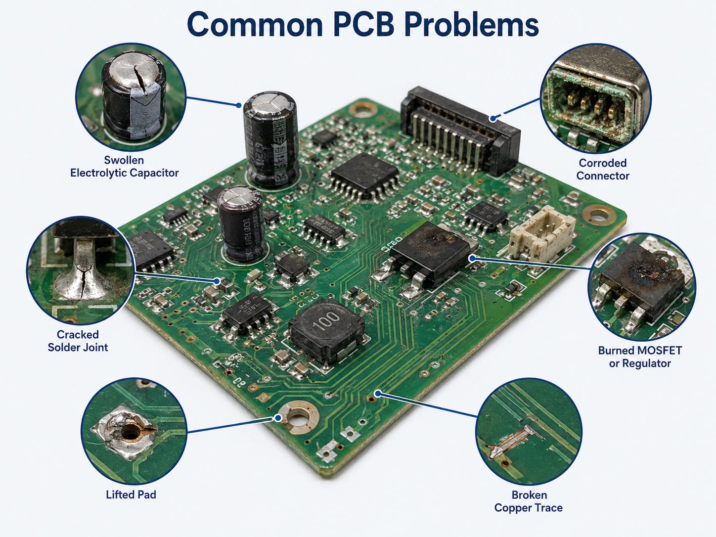
Common examples include:
- high-ESR or failed electrolytic capacitors;
- worn relays;
- oxidized or damaged connectors;
- cracked solder joints;
- failed MOSFETs, IGBTs, regulators, or diodes;
- overheated resistors;
- lifted pads;
- broken copper traces;
- damaged plated-through holes;
- localized corrosion;
- deteriorated conformal coating;
- contamination from dust, moisture, or residues.
The visible failure is not always the root cause. A burned MOSFET may have failed because of a damaged gate-drive circuit, excessive load, or another power-stage problem.
Corrosion also needs careful assessment. Surface corrosion near a connector may be manageable, while corrosion beneath packages or inside vias can be much harder to restore reliably.
How Is a Circuit Board Refurbished?
A typical refurbishment process moves from diagnosis to controlled rework and then verification.
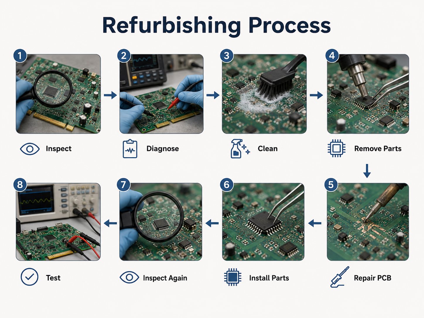
1. Review the fault history
Record the board model, symptoms, operating conditions, previous repairs, and when the failure occurs. Intermittent, temperature-related, and load-related faults can point to different failure mechanisms.
2. Inspect the board
Visual and microscopic inspection may reveal:
- burned components;
- cracked joints;
- corrosion;
- damaged connectors;
- swollen capacitors;
- lifted pads;
- coating damage;
- previous poor-quality rework.
3. Diagnose the electrical fault
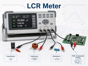
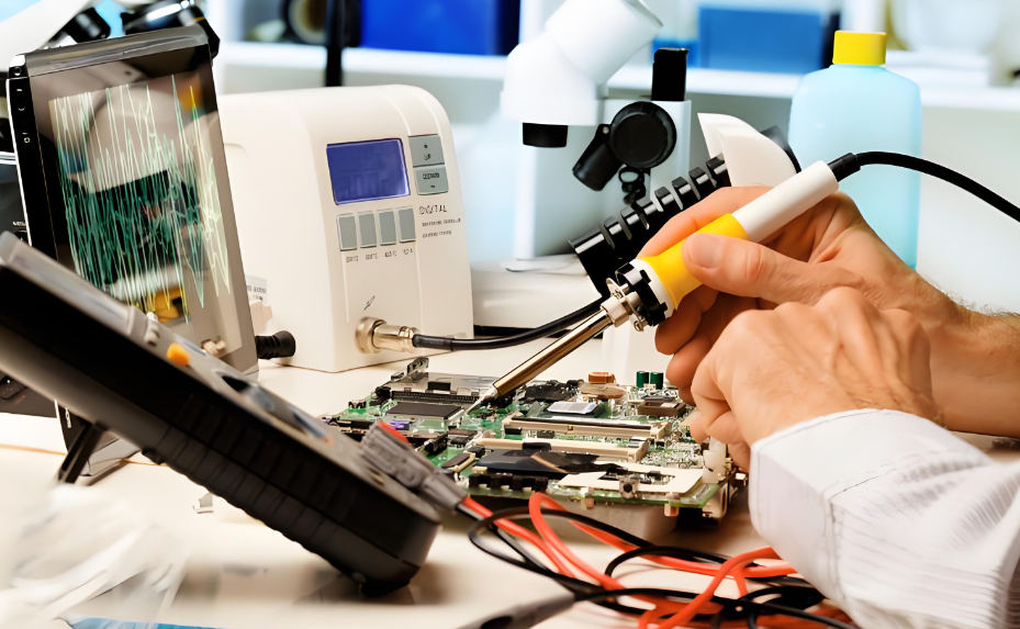
Testing may include continuity checks, resistance measurements, power-rail analysis, signal tracing, diode-mode measurements, and comparison with a known-good board.
4. Clean contaminated areas
Flux residue, dust, oils, and corrosion products may interfere with inspection or electrical performance. Proper cleaning of PCB assemblies after soldering helps technicians expose defects and remove residues. Cleaning materials must be compatible with the PCB, plastics, labels, coatings, and components.
5. Remove defective components
Removal technique depends on the package. A through-hole relay, small resistor, QFN, and BGA each require different tools and thermal control.
6. Repair PCB damage
Localized board restoration may include:
- pad repair;
- trace repair;
- via repair;
- conductor reinforcement;
- solder-mask restoration;
- limited laminate repair.
7. Install replacement parts
Replacement components must match the required electrical ratings, package, polarity, thermal capability, and circuit function.
8. Inspect and test
The reworked area is inspected before the board moves to electrical and functional verification.
Which Components Are Commonly Replaced During Refurbishing?
Components exposed to mechanical wear, heat, or gradual electrical degradation usually receive the most attention.
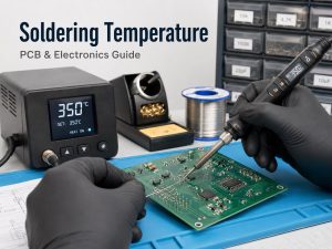
For basic work, a circuit board repair kit and suitable circuit board repair tools may cover through-hole components, but fine-pitch PCB refurbishment and PCB restoration require controlled heating, inspection, and test equipment.
Frequently evaluated parts include:
- electrolytic capacitors;
- relays;
- connectors;
- MOSFETs and IGBTs;
- rectifiers;
- voltage regulators;
- optocouplers;
- heat-stressed resistors;
- damaged ICs.
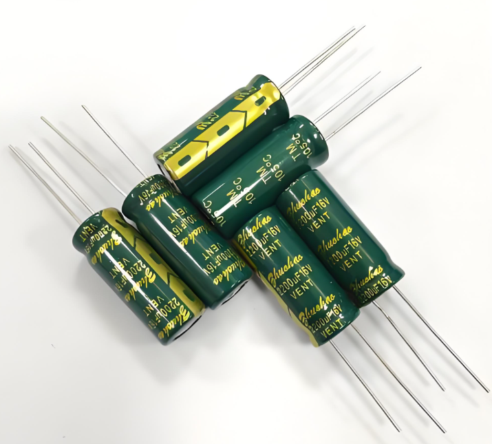
Electrolytic capacitors are commonly checked because capacitance, ESR, leakage, and temperature exposure can change over time.
Relays may still actuate mechanically even when their contacts have become resistive or unreliable under load. Connectors can develop similar intermittent faults through oxidation, vibration, or repeated mating cycles.
Parts should not be replaced only because the board is old. Unnecessary rework adds thermal cycles and handling stress to the PCB.
How Are BGA and SMD Components Reworked During PCB Refurbishment?
Fine-pitch SMD and BGA refurbishment requires tighter process control than conventional through-hole repair.
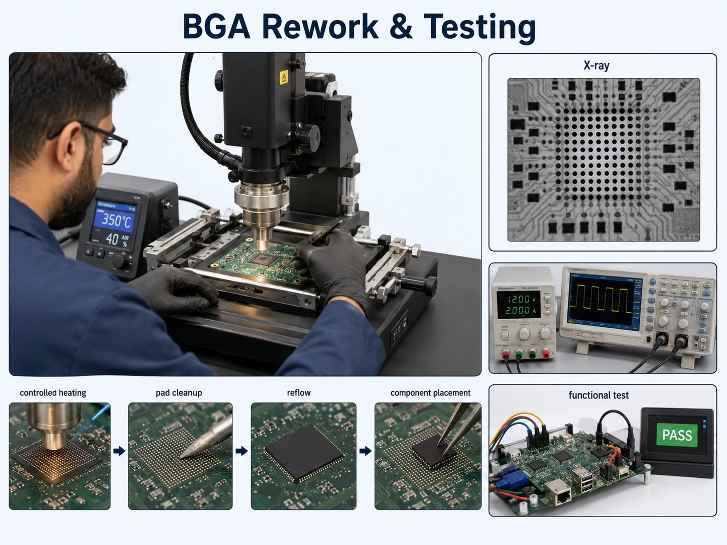
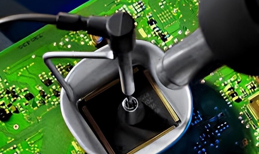
A BGA rework may involve:
- confirming that the device or solder interface is defective;
- protecting nearby components;
- controlling top and bottom heating;
- removing the package without lifting pads;
- cleaning and inspecting the land pattern;
- repairing damaged pads if necessary;
- reballing or preparing the replacement component;
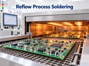
- aligning and reflowing the device;
- inspecting hidden joints by X-ray.
Poor thermal control can warp the PCB, damage laminate, lift pads, or overheat adjacent components.
QFN packages create a similar inspection challenge because part of the solder interface sits beneath the component and cannot be fully checked optically.
How Is a Refurbished Circuit Board Tested?
Testing should confirm that the original fault has been corrected without introducing another defect. A documented PCB inspection step also helps verify workmanship before functional testing.
Depending on the assembly, verification may include:
- visual and microscopic inspection;
- continuity and resistance checks;
- short-circuit checks before power-up;
- controlled power-up with current limiting;
- voltage-rail verification;
- signal and I/O testing;
- communication testing;
- relay or actuator operation;
- functional testing;
- load testing;
- X-ray inspection for hidden joints;
- thermal inspection.
Functional testing is particularly important. Confirming a 5 V rail, for example, does not prove that an industrial controller can read sensors, communicate with another device, drive its outputs, and remain stable under load.
When Is a Circuit Board Not Worth Refurbishing?
Refurbishment becomes difficult to justify when damage is widespread, structural, or impossible to verify after repair.
Warning signs include:
- severe laminate carbonization;
- extensive delamination;
- major internal-layer damage;
- widespread corrosion;
- badly damaged BGA pad fields;
- repeated previous repairs in the same area;
- large areas affected by overheating;
- unavailable proprietary ICs;
- inaccessible firmware or programmed devices;
- safety-critical boards without an approved repair route;
- refurbishment cost close to the cost of replacement.
Carbonized PCB material deserves particular caution because it can become electrically conductive. Covering a burned area with coating or epoxy does not necessarily restore its original insulation properties.
Repeated heating can also weaken pads, plated-through holes, and laminate adhesion.
Circuit Board Refurbishing vs Replacement: Which Should You Choose?
Refurbishment usually makes the most sense when the board is valuable, difficult to replace, and affected by a localized fault that can be properly tested afterward.
| Situation | More Practical Choice |
| OEM board is discontinued | Refurbish |
| Replacement lead time is long | Refurbish |
| High-value industrial board | Evaluate refurbishment |
| Failure is localized | Repair or refurbish |
| Extensive laminate damage | Replace |
| New board is inexpensive and available | Replace |
| Critical IC is unavailable | Replacement may be necessary |
| Functional testing is impossible | Further engineering evaluation |
| Several areas have repeatedly failed | Consider replacement |
The comparison should include more than the price of the board. Downtime, machine qualification, software compatibility, installation work, spare-part availability, and equipment lifecycle can materially change the economics.
What Standards Apply to Circuit Board Rework and Refurbishment?
IPC-7711/7721 is one of the main references for electronic assembly rework, modification, and repair. It covers procedures associated with component removal and installation as well as land, conductor, laminate, and coating repair.
Other relevant standards can include:
- J-STD-001 — requirements for soldered electrical and electronic assemblies;
- IPC-A-610 — acceptance criteria for electronic assemblies.
The applicable requirement depends on the product, customer specification, assembly class, and industry.
Medical, aerospace, automotive, military, and other controlled applications may impose additional limits on permitted repairs and required documentation.
What Information Should You Provide for Circuit Board Refurbishing?
Clear fault information can reduce diagnostic time and help technicians reproduce the problem.
Useful materials include:
- photos of both sides of the board;
- PCB or assembly part number;
- equipment model;
- detailed fault symptoms;
- operating voltage;
- schematics;
- BOM;
- PCB drawings or Gerber files;
- firmware information;
- previous repair history;
- known damaged components;
- expected I/O behavior;
- test procedures;
- a known-good board for comparison.
A description such as “the board does not work” provides little diagnostic value.
A more useful report would be:
“The 24 V input is present, but the 5 V rail falls to 1.8 V after about 20 seconds and U17 becomes unusually hot.”
For intermittent faults, temperature, vibration, load, startup conditions, and operating duration can also help narrow down the cause.
FAQs About Circuit Board Refurbishing
Can an old circuit board be refurbished?
Yes. Older boards can often be refurbished when the PCB remains structurally sound, replacement components are available, and operation can be properly verified after repair.
Can a corroded circuit board be refurbished?
Localized surface corrosion may be repairable. Severe corrosion beneath components, inside vias, or across internal conductors can make restoration much more difficult.
How long can a refurbished circuit board last?
There is no fixed service-life figure. Remaining life depends on the original board condition, component age, operating temperature, electrical load, environment, and quality of the repair.
Is circuit board refurbishing cheaper than replacement?
It often can be for expensive, discontinued, or proprietary assemblies. For low-cost boards that remain readily available, replacement may be more economical.
Can obsolete circuit boards be refurbished?
Yes. Discontinued industrial boards are common refurbishment candidates, although obsolete components, programmed devices, missing documentation, and limited test access can complicate the work.
Can multilayer PCBs and BGA assemblies be refurbished?
Yes, if the damage is repairable and suitable equipment is available. Multilayer conductor damage and hidden-joint packages generally require more specialized rework and inspection than simple component replacement.
What Is the Best Next Step for an Aging Circuit Board?
Start with the board’s fault history, physical condition, replacement availability, and test access. Choose circuit board refurbishment when the defect is localized and the repaired functions can be verified; choose replacement when damage is structural, widespread, or cannot be tested reliably.