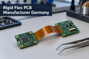
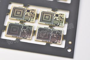
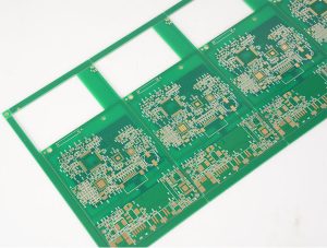
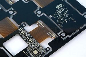
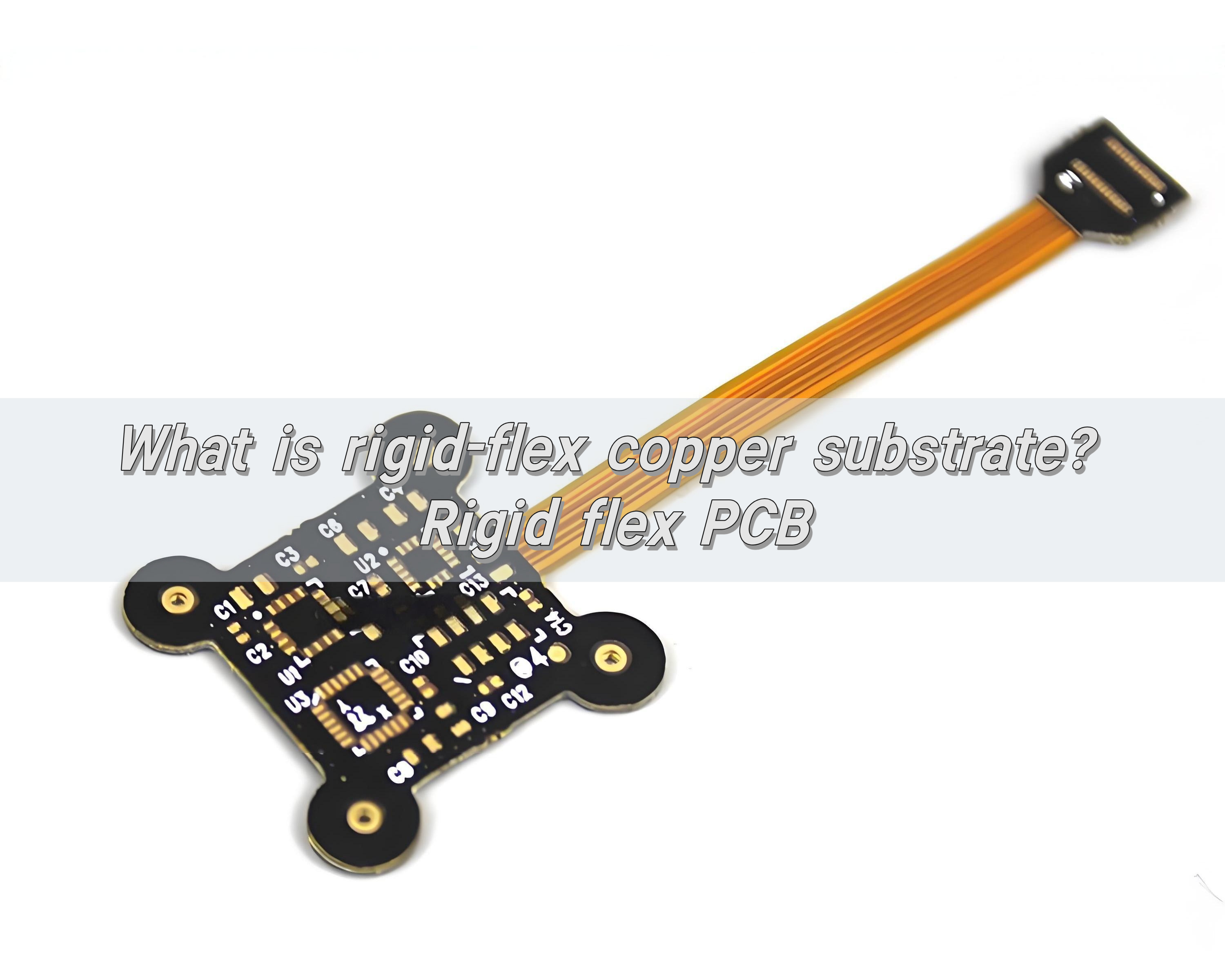
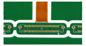
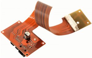
Choosing a rigid flex PCB manufacturer is not only about finding a supplier that can fabricate flexible and rigid materials together. For medical electronics, industrial sensors, compact modules, aerospace electronics, and high-density devices, the manufacturer must understand stackup control, bend reliability, impedance, material selection, surface finish, assembly, documentation, and traceability.
EBest Circuit (Best Technology) supports rigid-flex PCB manufacturing, DFM review, component sourcing, PCBA assembly, inspection, and production documentation for custom projects. If you require rigid-flexible PCB made in China, you can send your Gerber files, ODB++ files, stackup drawing, impedance notes, BOM, assembly notes, or special quality requirements to sales@bestpcbs.com. Our engineering team can help review the manufacturing path before production starts.
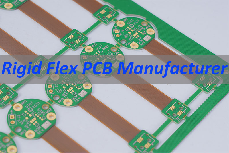
What Makes a Good Rigid Flex PCB Manufacturer?
A good rigid flex PCB manufacturer should be able to handle both the electrical and mechanical risks of the board. Rigid-flex PCB is different from a standard FR4 PCB because the flex area is not only a routing area. It is also a bending, folding, or space-saving structure inside the final product.
When evaluating a supplier, focus on the points that affect real production:
| Checkpoint | Why It Matters |
|---|---|
| Stackup | Controls thickness, impedance, and lamination risk |
| Flex material | Affects bend reliability and lifetime |
| Bend area | Prevents copper cracking and stress concentration |
| Impedance | Supports high-speed signal stability |
| Surface finish | Affects solderability and connector reliability |
| PCBA support | Reduces handoff risk after fabrication |
| Documentation | Important for medical and industrial projects |
For medical electronics, the best supplier is usually not the cheapest one. It is the one that can identify risk before production starts.
Top 10 Rigid-Flex PCB Manufacturers in China
This list is not a formal revenue ranking. It is a practical buyer-oriented list of rigid-flex PCB manufacturers and PCB suppliers commonly considered by engineers sourcing from China or China-based supply chains.
1. EBest Circuit (Best Technology)
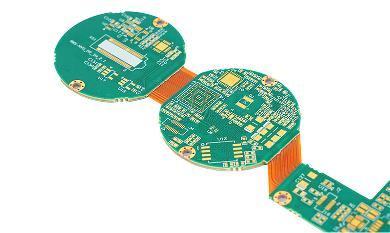
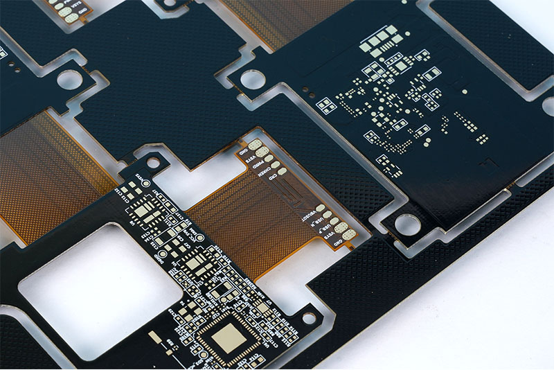
- EBest Circuit is suitable for customers who need rigid-flex PCB manufacturing plus one-stop PCB and PCBA support. The company supports custom PCB fabrication, component sourcing based on approved BOM, SMT assembly, DFM review, testing, and documentation. For medical electronics, automotive electronics, aerospace electronics, industrial modules, and compact devices, EBest Circuit’s value is in engineering review and production coordination, not only bare board fabrication.
- Best fit: rigid-flex PCB, FPC, HDI, FR4 PCB, ceramic PCB, metal core PCB, PCBA assembly, prototype, small batch, and production projects.
2. PCBWay
- PCBWay is widely known for online PCB prototyping and custom PCB manufacturing. It is often considered by engineers who need fast quoting, broad PCB service coverage, and flexible prototype support. For rigid-flex PCB projects, it can be useful for prototype-stage sourcing, but complex medical or high-reliability projects still need careful review of drawings, stackup, test requirements, and assembly expectations.
- Best fit: online PCB quoting, prototypes, small-batch rigid-flex PCB, and general PCB manufacturing.
3. JLCPCB
- JLCPCB is popular among engineers, makers, and product teams because of its online ordering system, fast prototype service, and integration with component sourcing and assembly workflows. It is often a strong option for standard PCB prototypes and cost-sensitive development. For more complex rigid-flex PCB or high-reliability medical electronics, buyers should confirm material, tolerance, stackup, inspection, and documentation requirements before placing an order.
- Best fit: fast prototypes, standard PCB fabrication, cost-sensitive projects, and early-stage validation.
4. Hemeixin Electronics
- Hemeixin is known in the PCB market for advanced PCB manufacturing, including HDI, rigid-flex, and high-layer-count boards. It is often considered when the project requires more advanced fabrication capability than a simple prototype board. For engineers working on compact electronics, its strength is usually in more complex board structures.
- Best fit: HDI PCB, rigid-flex PCB, high-density routing, and advanced multilayer PCB projects.
5. RayPCB
- RayPCB provides a wide PCB manufacturing range, including rigid PCB, flexible PCB, rigid-flex PCB, HDI PCB, RF PCB, and PCBA services. It is often visible in search results for technical PCB topics and manufacturing guides. Buyers can consider it when comparing suppliers for rigid-flex capability, but should still validate project-specific requirements such as impedance, material, layer count, IPC class, and assembly details.
- Best fit: broad PCB manufacturing, rigid-flex PCB, HDI PCB, RF PCB, and PCB assembly.
6. Viasion Technology
- Viasion positions itself as a PCB and PCBA supplier with rigid-flex PCB manufacturing support. It can be considered by customers comparing China-based rigid-flex suppliers with assembly capability. For complex applications, buyers should check whether the supplier can support the exact stackup, flex construction, impedance, surface finish, and inspection documents required.
- Best fit: rigid-flex PCB, PCB assembly, custom PCB projects, and turnkey support.
7. PCBONLINE
- PCBONLINE is often considered for multilayer PCB, HDI PCB, rigid-flex PCB, and special PCB projects. It may be suitable for customers looking for technical manufacturing support rather than only standard low-cost PCB prototypes. For higher-reliability products, engineering confirmation before production is important.
- Best fit: multilayer PCB, HDI PCB, rigid-flex PCB, and special PCB manufacturing.
8. NextPCB
- NextPCB is another online-accessible PCB supplier that supports PCB fabrication and assembly services. It is often considered for prototype and small-batch PCB projects. For rigid-flex PCB projects, customers should provide clear drawings, bend requirements, stackup notes, and material requirements before production.
- Best fit: prototype PCB, small-batch PCB, PCB assembly, and online sourcing.
9. MOKO Technology
- MOKO Technology provides electronics manufacturing and PCB assembly services. It may be considered when the project needs more than bare PCB fabrication, especially if the customer needs PCBA, testing, and product-level manufacturing support. For rigid-flex projects, the manufacturing details should be confirmed based on the exact board structure.
- Best fit: PCB assembly, electronics manufacturing, turnkey support, and small-to-medium production.
10. ALLPCB
- ALLPCB is known as an online PCB manufacturing platform with prototype and batch PCB services. It may be useful for standard projects and early-stage comparisons. For medical electronics or complex rigid-flex PCB, customers should confirm whether the project requirements fit the supplier’s process capability before ordering.
- Best fit: online PCB manufacturing, prototype PCB, batch PCB, and general PCB sourcing.
Best Rigid Flex PCB Manufacturer for Medical Electronics
For medical electronics, a rigid-flex PCB manufacturer should understand that the board is part of a reliability chain. The PCB may sit inside a handheld diagnostic device, wearable medical sensor, imaging module, monitoring device, or compact electronic instrument. In these products, a small manufacturing issue can affect assembly yield, connector stability, signal quality, or long-term reliability.
A medical electronics rigid-flex PCB project often needs stable material selection, controlled board thickness, reliable flex-to-rigid transition areas, clean ENIG surface finish, controlled impedance when signals require it, SMT assembly support, inspection records, and traceable production documentation.
EBest Circuit is a strong fit when the customer needs both PCB manufacturing and PCBA coordination. With ISO9001, ISO13485, IATF16949, and AS9100D certifications, EBest Circuit can support customers who need stronger quality management and documentation awareness for medical, automotive, aerospace, and industrial electronics.
Semi-Flex PCB vs Rigid-Flex PCB
Semi-flex PCB and rigid-flex PCB are sometimes confused, but they are not the same.
| Item | Semi-Flex PCB | Rigid-Flex PCB |
|---|---|---|
| Material | Thin FR4 bending area | FR4 + PI flex layers |
| Flexibility | Limited bending | More reliable bending |
| Cost | Lower | Higher |
| Bend use | Usually installation only | Folding or controlled flex use |
| Best for | Simple 3D fit | Compact reliable modules |
Semi-flex PCB can be useful when the board only needs to bend slightly during installation. Rigid-flex PCB is better when the product needs a more reliable flex section, a smaller assembly volume, fewer connectors, or more stable long-term performance.
If a project involves repeated bending, tight space, fine-pitch assembly, impedance control, or medical electronics, rigid-flex PCB is usually the safer choice.
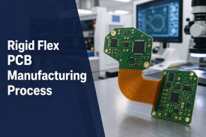
Rigid Flex PCB Manufacturing Process Explained
Rigid flex PCB manufacturing is more complex than standard rigid PCB manufacturing because the board contains both rigid and flexible areas. The process must control lamination, drilling, plating, coverlay, solder mask, surface finish, outline, and testing without damaging the flex area.
A typical rigid-flex PCB manufacturing process includes:
| Step | Key Control |
|---|---|
| File review | Gerber, drawing, stackup, bend notes |
| Material prep | FR4, PI, coverlay, stiffener, low-flow PP |
| Inner layers | Copper balance and fine lines |
| Lamination | Thickness and resin flow |
| Drilling | Mechanical holes, laser vias, blind/buried vias |
| Plating | Hole reliability and copper thickness |
| Coverlay | Flex protection and opening accuracy |
| Solder mask | Rigid area solder mask control |
| Surface finish | ENIG or project-specified finish |
| Testing | E-test, impedance test, inspection |
The most important step is early engineering review. If the stackup, bend area, or impedance structure is not reviewed before production, problems may only appear after lamination or assembly, when correction is much more expensive.
Rigid-Flex PCB Stackup and Material Selection
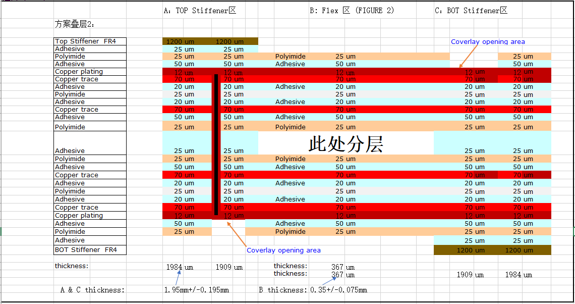
Rigid-flex PCB stackup defines how rigid layers and flexible layers connect. It affects board thickness, bend radius, impedance, mechanical reliability, assembly process, and final product fit.
A rigid-flex PCB stackup may include FR4 rigid core, polyimide flexible core, adhesive or adhesiveless flex material, copper foil, coverlay, low-flow prepreg, stiffener, and ENIG or another surface finish.
For rigid-flex PCB, the bend area should avoid unnecessary copper stress. Traces in the flex area should be routed smoothly, with suitable spacing and without sharp corners. If the product has controlled impedance, the manufacturer must calculate the trace geometry based on the actual stackup, dielectric thickness, copper thickness, and reference layer.
Medical electronics, sensors, imaging products, and compact modules often need a balance between thin structure, stable impedance, reliable bending, and manufacturable assembly.
EBest Circuit Rigid-Flex PCB Manufacturing Capabilities
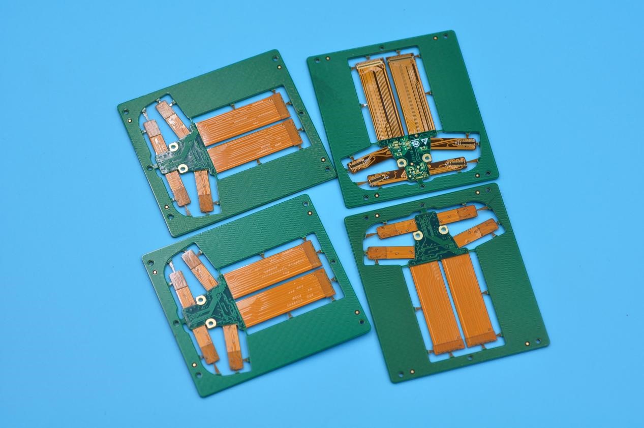
EBest Circuit supports rigid-flex PCB manufacturing for prototype, small-batch, and production projects where the board needs both mechanical flexibility and stable electrical performance. For many customers, the key question is not only whether a supplier can make a rigid-flex PCB, but whether the supplier can review the stackup, flex area, impedance, material, surface finish, panel delivery, and PCBA requirements before production starts.
Here are some rigid-flex PCB manufacturing capabilities that EBest Circuit can support or review according to project requirements:
| Capability | EBest Circuit Support |
|---|---|
| Rigid-flex layers | 2 to 20 layers |
| Finished thickness | 0.3mm to 3.0mm |
| Thickness tolerance | >1.0mm: ±10%; ≤1.0mm: ±0.10mm |
| Flex structure | Inner or outer flex layer support |
| Flex materials | PI, adhesiveless flex core, coverlay, stiffener |
| Rigid materials | FR4, high Tg FR4, low-flow PP |
| Fine features | Fine line/space, BGA pads, laser vias, mechanical drilling |
| Impedance | Controlled impedance review; typical tolerance ±10% |
| Surface finish | ENIG and other finishes based on project needs |
| PCBA support | BOM sourcing, SMT assembly, connector assembly, testing, packing |
For rigid-flex PCB projects, EBest Circuit pays special attention to the areas that often create risk: rigid-flex transition zones, bend areas, copper balance, coverlay openings, stiffener placement, impedance traces, drilling structure, and panelization for assembly.
This support is useful for customers developing medical electronics, industrial sensors, compact modules, aerospace electronics, automotive electronics, wearable devices, and other products where the PCB must fit into limited mechanical space while still supporting reliable assembly and signal performance.
Rigid-Flex PCB Manufacturing Case Study
A customer from Europe needed a high-layer rigid-flex PCB for a compact medical electronics module. The product required a thin structure, stable impedance, reliable bending performance, and controlled documentation before production.
Project requirements
- 14-layer rigid-flex PCB
- Tg180 material
- ENIG 1u”
- Green solder mask, white silkscreen
- Total thickness: 1.4mm ±10%
- Controlled impedance: 85 ohm ±10%
- Date code beside the logo in DD-MM-YYYY format
- Panel delivery required
- Production stackup and production files had to be confirmed by the customer before manufacturing
Main manufacturing challenges
The first challenge was the stackup. A 14-layer rigid-flex PCB cannot be treated like a standard multilayer rigid board. The rigid area, flex area, dielectric thickness, copper thickness, and bonding materials all had to be reviewed together.
The second challenge was impedance control. Because the customer required 85 ohm ±10%, the stackup and trace geometry had to be checked before production, not only measured after the board was finished.
The third challenge was documentation control. For this project, EBest Circuit needed to prepare the production stackup and production files first, send them to the customer for confirmation, and then arrange manufacturing after approval.
EBest Circuit’s manufacturing support
- Reviewed the customer’s original stackup reference before production
- Prepared a production stackup for customer confirmation
- Checked impedance feasibility based on the final production structure
- Confirmed ENIG, solder mask, silkscreen, date code, and panel delivery requirements
- Controlled the rigid-flex transition area to reduce manufacturing risk
- Managed the project under a documented PCB production process
For the customer, the value was not only receiving a 14-layer rigid-flex PCB. The more important value was that the key production details were confirmed before fabrication started: stackup, impedance, material, date code, panel format, and manufacturing files. This helped reduce communication gaps and made the project easier to move from engineering review to production.
Why Choose EBest Circuit as Your Reliable Rigid Flex PCB Manufacturer?
EBest Circuit is suitable for customers who need a rigid flex PCB manufacturer that can support both manufacturing and assembly-related project control.
Customers choose EBest Circuit for rigid-flex PCB projects because the team can support PCB fabrication and PCBA assembly in one workflow, engineering review before production, DFM checking for manufacturability risks, BOM sourcing based on the approved BOM, SMT assembly, connector assembly, prototype and small-batch production, documented quality control, and digital production traceability.
For medical electronics and compact modules, this one-stop support can reduce handoff problems between PCB fabrication, assembly, inspection, and final delivery.
If you are developing a rigid-flex PCB project, you can send your Gerber files, ODB++ files, drawings, stackup, impedance notes, BOM, assembly notes, or quality requirements to sales@bestpcbs.com. EBest Circuit’s engineering team can help review the manufacturing path before production starts.
FAQs about Rigid Flex PCB Manufacturer
1. What is a rigid flex PCB manufacturer?
A rigid flex PCB manufacturer produces circuit boards that combine rigid PCB sections and flexible PCB sections in one structure. These boards are used when the product needs compact assembly, bending, folding, or fewer connectors.
2. How do I choose a rigid flex PCB manufacturer?
Choose a supplier that can review stackup, flex material, bend area, impedance, surface finish, PCBA requirements, and documentation before production. For medical electronics, quality systems and traceability are also important.
3. What is the difference between semi-flex PCB and rigid-flex PCB?
Semi-flex PCB usually uses a thinner FR4 bending area and is suitable for limited bending. Rigid-flex PCB uses flexible PI material and is better for products that need stronger bending reliability or compact 3D assembly.
4. Can rigid-flex PCB support controlled impedance?
Yes. Rigid-flex PCB can support controlled impedance, but the stackup, trace width, dielectric thickness, copper thickness, and reference layer must be reviewed before production.
5. Is rigid-flex PCB suitable for medical electronics?
Yes. Rigid-flex PCB is widely used in compact medical electronics, wearable devices, monitoring modules, and diagnostic equipment. The key is choosing a manufacturer that can support material control, stackup review, assembly, testing, and documentation.
Need help with a rigid-flex PCB project? If your project involves rigid-flex stackup, bend area reliability, controlled impedance, ENIG finish, PCBA assembly, or production documentation, send your Gerber files, ODB++ files, drawings, stackup notes, BOM, or assembly requirements to sales@bestpcbs.com. EBest Circuit’s engineering team will help review the manufacturing path before production starts.