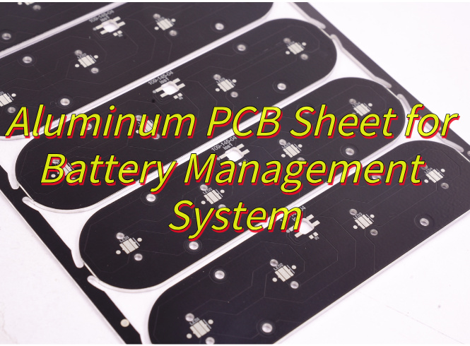
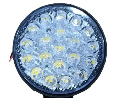
Is your motorcycle LED light aluminum PCB reliable enough for outdoor riding? If you’re struggling with overheating, vibration damage, or short lifespans from your motorcycle LED light PCB, you need a solution you can trust. Choose EBest’s motorcycle LED light aluminum PCB, we deliver top-tier quality, on-time delivery, stable supply chains, and responsive service to solve all your outdoor riding lighting woes. This blog breaks down why aluminum PCBs are the best choice for motorcycle LEDs, how they solve common pain points, and where to get the best products for your project.
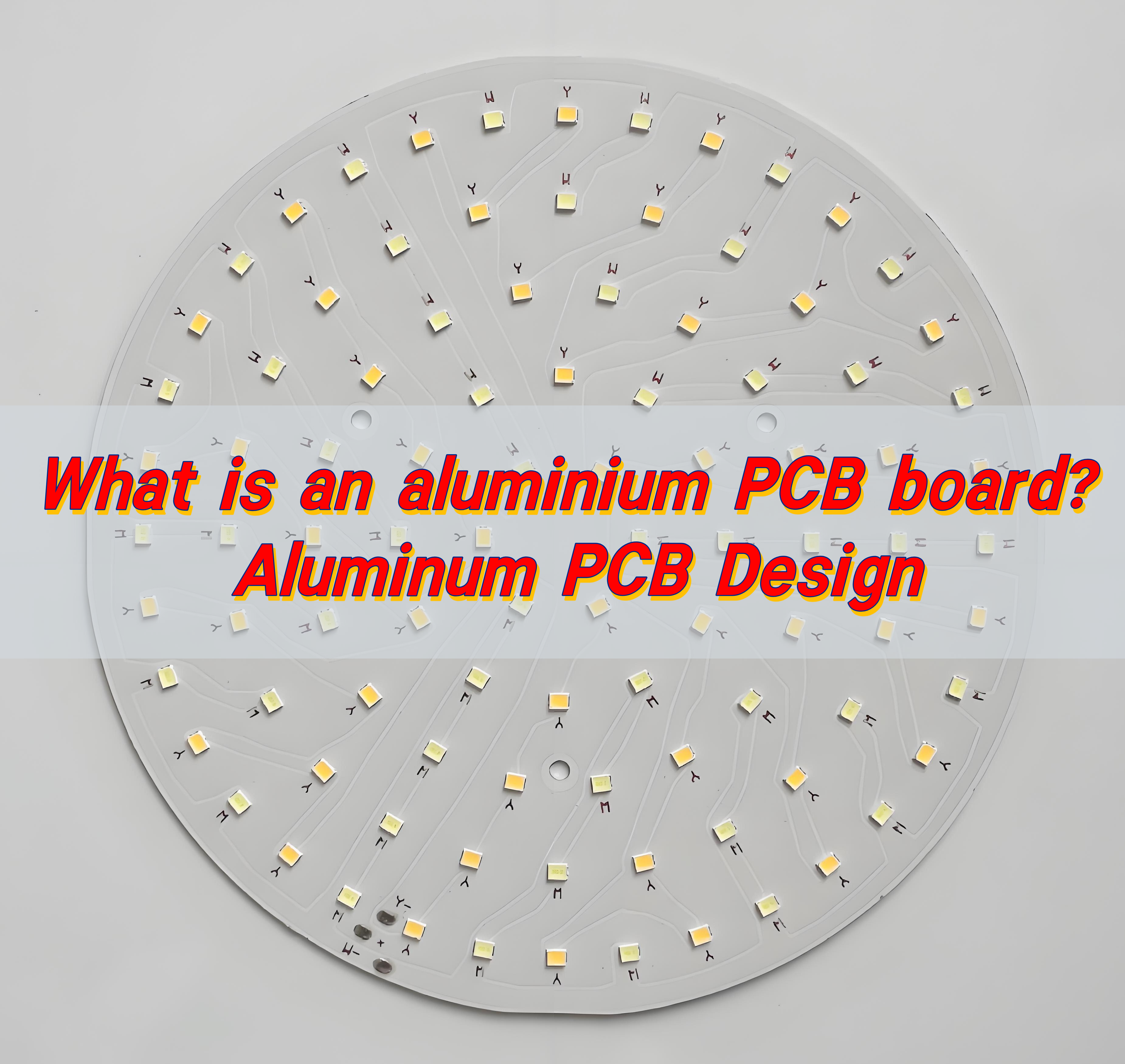
Why Choose Aluminum PCB for Motorcycle LED Lights?
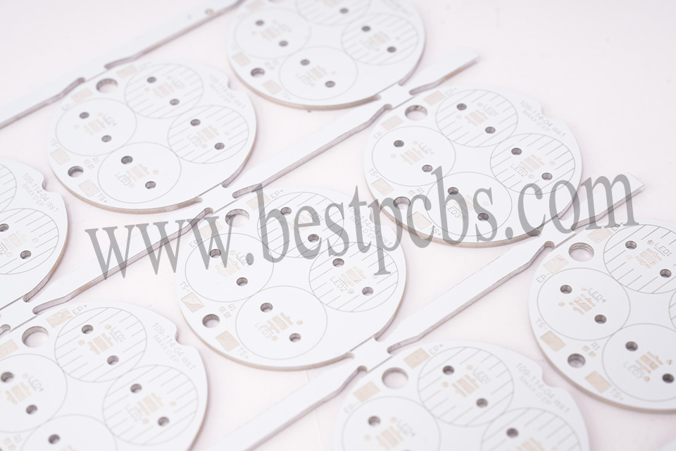
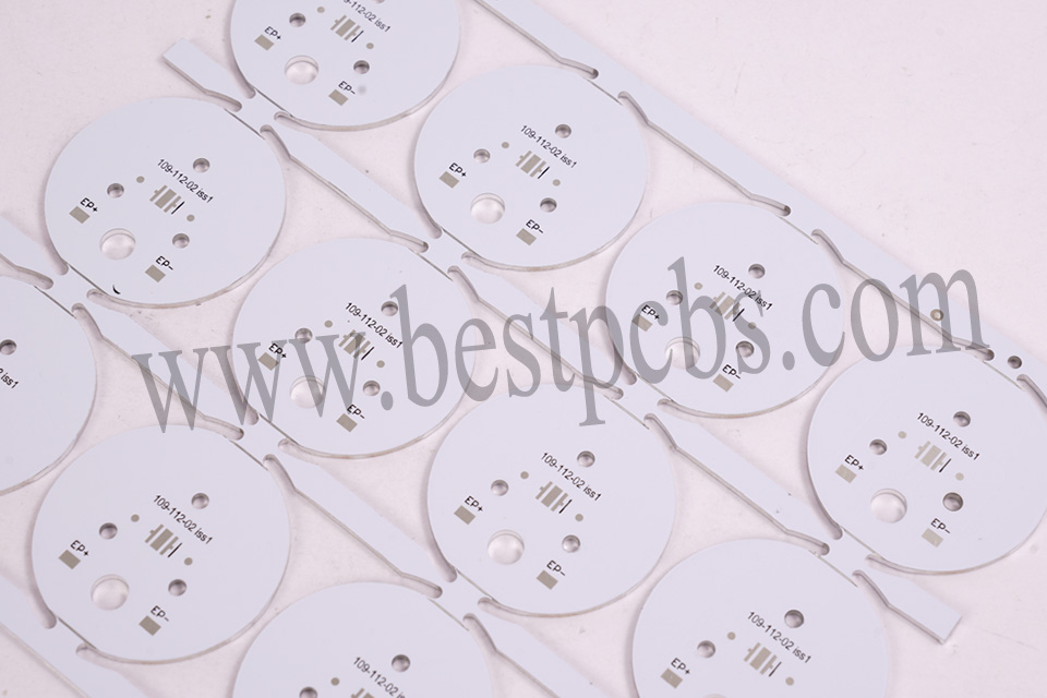
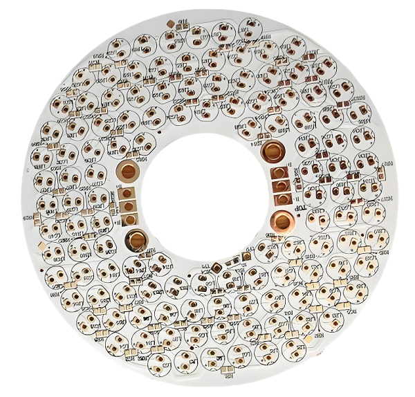
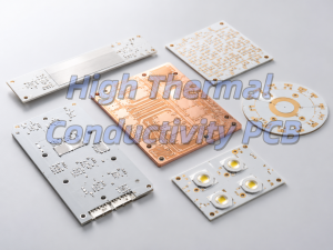
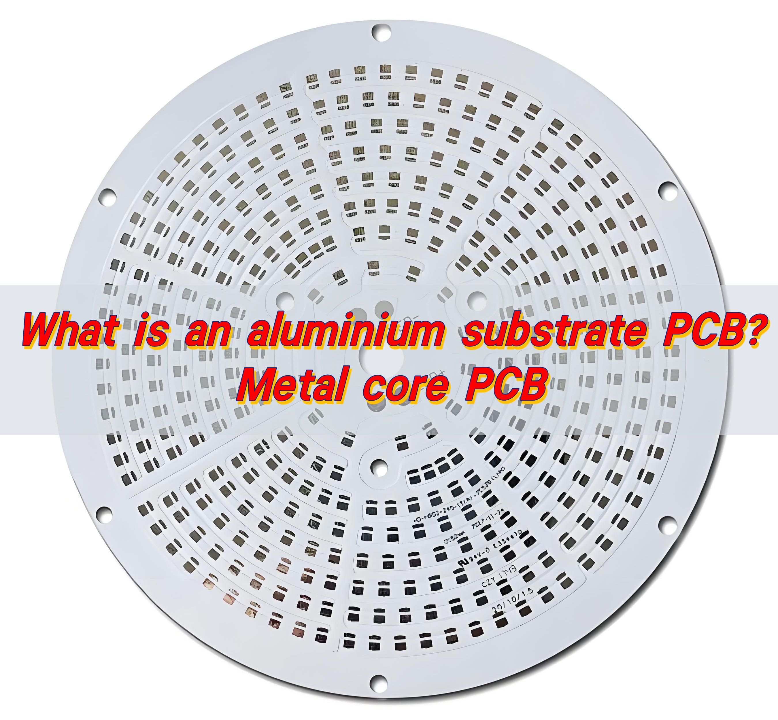
Aluminum PCBs are the optimal choice for motorcycle LED lights, as they’re engineered to tackle the harsh outdoor and off-road conditions that traditional PCBs struggle with. Their unique metal core design delivers unmatched thermal management, durability, and versatility, making them a reliable foundation for motorcycle lighting systems.
- Exceptional thermal conductivity: Rapidly dissipates heat from LED chips, preventing burnout and extending light lifespan, critical for long rides and high-power LEDs.
- Strong vibration resistance: Rigid aluminum base absorbs off-road shocks, keeping solder joints intact and avoiding component damage from rough terrain.
- Compact, space-saving design: Thinner and lighter than FR4 PCBs, fitting easily into tight motorcycle light housings without sacrificing performance.
- Waterproof-compatible: Works seamlessly with protective coatings (like IP67) to fend off rain, mud, and moisture, ensuring reliability in all weather.
- Cost-effective durability: Reduces the need for extra cooling hardware, lowers long-term maintenance costs, and stands up to extreme temperature fluctuations (-40°C to 125°C).
How Does High Thermal Conductivity Solve Motorcycle Light Overheating?
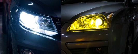
Overheating is the top cause of LED failure in motorcycle lighting, especially during long outdoor rides or in extreme temperatures. LEDs are sensitive to heat, and excess warmth quickly leads to brightness dimming, premature burnout, and shortened lifespans.
High thermal conductivity in motorcycle LED light aluminum PCB addresses this by acting as a heat conductor, rapidly transferring heat away from LED chips. Unlike traditional PCBs, aluminum’s core design ensures heat doesn’t accumulate around the LED components.
Aluminum boasts a thermal conductivity of 200-237 W/mK, which is drastically higher than FR4 PCBs (0.2-0.4 W/mK). This gap means aluminum PCBs dissipate heat far faster, keeping LEDs within their optimal operating temperature range.
By reducing heat buildup, Motorcycle LED Light Aluminum PCB prevents light decay and component damage. This not only extends LED lifespan by 30-50% but also ensures consistent brightness during long rides, critical for rider safety.
The aluminum base also eliminates the need for extra cooling hardware, keeping motorcycle LED lights compact and lightweight, perfect for tight mounting spaces on bikes.
Can Your LED Lights Handle Off-Road Vibration?
Yes, Off-road riding exposes motorcycle LED lights to constant, intense vibration, far more than standard on-road use. This vibration is a major threat to PCB durability, as traditional PCBs often crack, have loose solder joints, or disconnect components after repeated exposure to rough terrain, leading to sudden light failure when you need it most.
The solution lies in choosing a high-quality motorcycle LED light aluminum PCB. Unlike fragile traditional substrates, aluminum PCBs have a rigid, sturdy base that acts as a shock absorber, dampening vibration and keeping critical components secure. This inherent rigidity prevents the structural damage that plagues other PCB materials in off-road conditions.
To ensure maximum reliability, EBest’s motorcycle LED light aluminum PCB undergoes strict vibration testing, adhering to industry standards with a frequency range of 10-2000Hz and 10g acceleration. This rigorous testing guarantees our PCBs hold up to even the harshest off-road trails, keeping your LED lights functional and your rides safe, no matter the terrain.
Waterproof Riding Worries: Is Your Motorcycle Light PCB Protected?
For outdoor and off-road riders, waterproof protection for your motorcycle LED light aluminum PCB is non-negotiable. Rain, mud, dew, and even pressure washing expose PCBs to moisture, which seeps into unprotected components and causes short circuits, leading to unexpected light failure when you need visibility most.
Unlike traditional PCBs that struggle with moisture resistance, high-quality motorcycle LED light aluminum PCB is designed to work seamlessly with advanced waterproof coatings. EBest uses conformal coatings, thin, non-conductive polymer films that conform to the PCB’s shape, covering traces and solder joints to block out moisture effectively.
Our PCBs meet IP67 waterproof standards, meaning they are dust-tight and protected against temporary submersion (1 meter depth for 30 minutes), passing rigorous testing that simulates heavy rain and off-road mud exposure. Sealed solder joints and durable coatings ensure your motorcycle LED lights stay functional, no matter the weather or terrain.
Small Size, Big Power: How Do Aluminum PCBs Fit Tight Motorcycle Spaces?
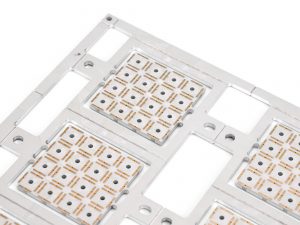
Motorcycle LED lights, whether headlights, turn signals, or auxiliary lights are designed to be compact, as motorcycle handlebars, fairings, and light housings have limited space. This means the Motorcycle LED Light Aluminum PCB inside must be small and lightweight, without sacrificing the performance needed for safe outdoor riding.
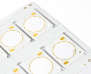
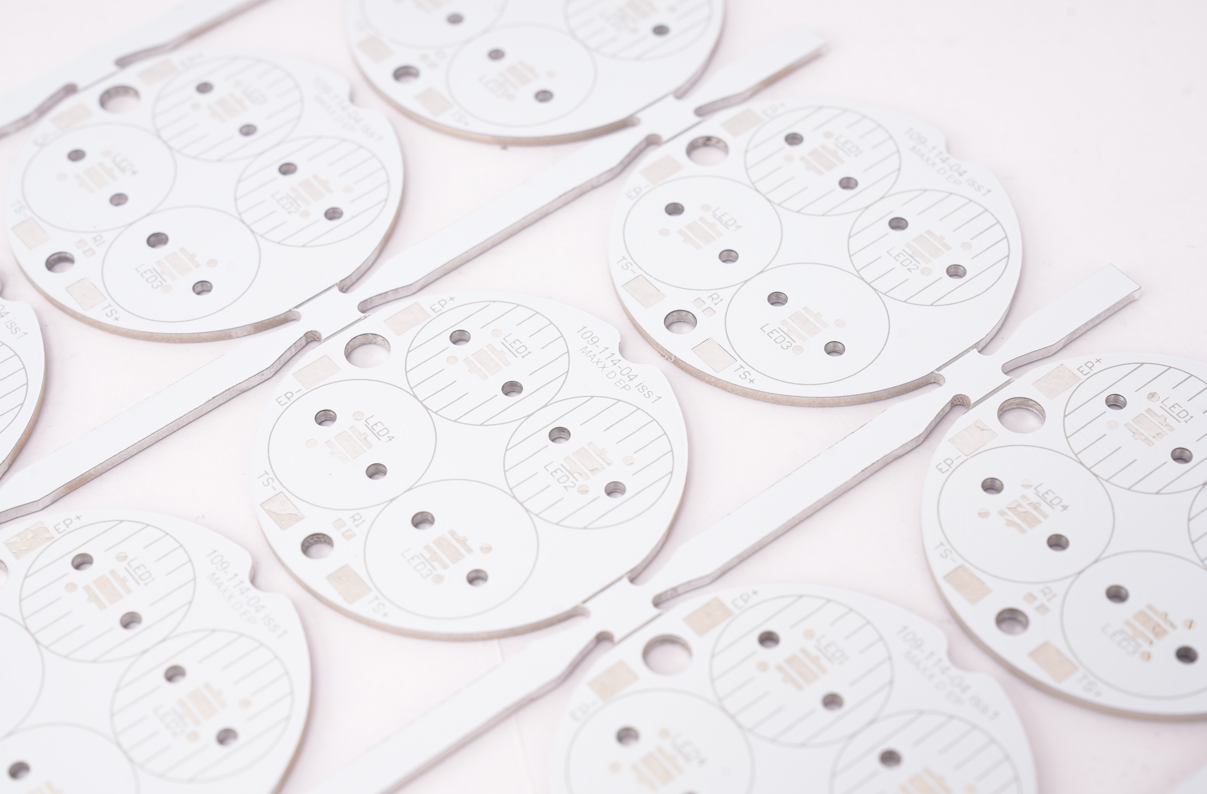
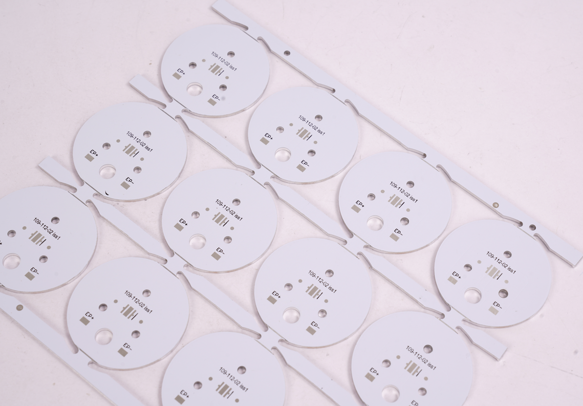
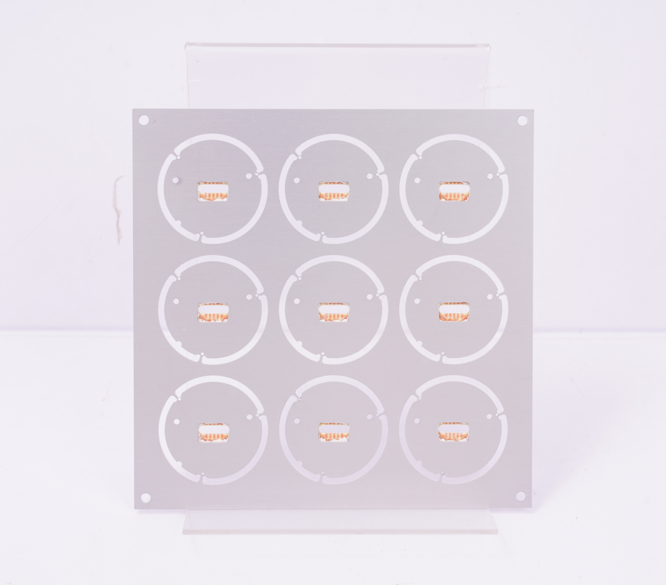
Unlike traditional FR4 PCBs, aluminum PCBs have a unique three-layer structure (aluminum core between copper foil and dielectric layer) that eliminates the need for extra cooling components, which often add bulk. This streamlined design keeps the PCB thin while maintaining structural rigidity, a key advantage for tight mounting spaces.
EBest’s motorcycle LED light aluminum PCB is engineered to a thickness of 0.8-1.2mm, 30% thinner than standard FR4 PCBs, making it easy to fit into slim light housings, even those with narrow internal dimensions like the compact copper housings used in high-power motorcycle headlights. This thin profile never compromises performance, as the aluminum core still delivers exceptional thermal conductivity.
The compact design of aluminum PCBs also simplifies installation, especially for custom motorcycle LED projects. Their lightweight nature reduces strain on light mounts, and their slim profile fits seamlessly with the small wiring holes (often 7/64″ or smaller) common in motorcycle light housings, ensuring a clean, secure fit without modifying the bike’s existing setup.
Long Rides, Reliable Lights: Does Your PCB Ensure Durability?
For motorcycle riders, especially those who love long-distance or off-road adventures, PCB durability directly impacts riding safety and peace of mind. A faulty PCB can cause sudden LED light failure mid-ride, leaving you without critical visibility, which is why your motorcycle LED light’s PCB must be built to last as long as your bike.
Unlike traditional FR4 PCBs that crack, warp, or fail under harsh conditions, motorcycle LED light aluminum PCB is engineered for long-term reliability. Its rigid aluminum core resists corrosion, wear, and the thermal stress caused by constant temperature changes, common issues that shorten the lifespan of other PCB materials.
EBest’s motorcycle LED light aluminum PCB is rigorously tested to withstand extreme temperature ranges of -40°C to 125°C, making it suitable for all climates, from freezing mountain rides to scorching desert adventures. This wide temperature tolerance prevents insulation layer peeling or component damage, thanks to its well-matched thermal expansion coefficient with copper foil.
Our customers consistently report an average lifespan of 5+ years for our PCBs, even with daily outdoor and off-road use. This durability eliminates the need for frequent replacements, saving time and hassle while ensuring your LED lights stay reliable, no matter how long or tough your rides are.
Cost vs. Quality: Finding the Best Value Aluminum PCB for LED Lights
When sourcing motorcycle LED light aluminum PCB, balancing cost and quality is a top priority for most projects, overpaying for unnecessary features wastes budget, while cutting costs on critical components leads to frequent failures and higher long-term expenses.
True value for motorcycle LED light aluminum PCB lies not in the lowest price, but in a combination of reliable performance, durability, and consistent supply. Opting for cheap, low-quality PCBs often results in overheating, vibration damage, or moisture issues, requiring costly replacements and project delays.
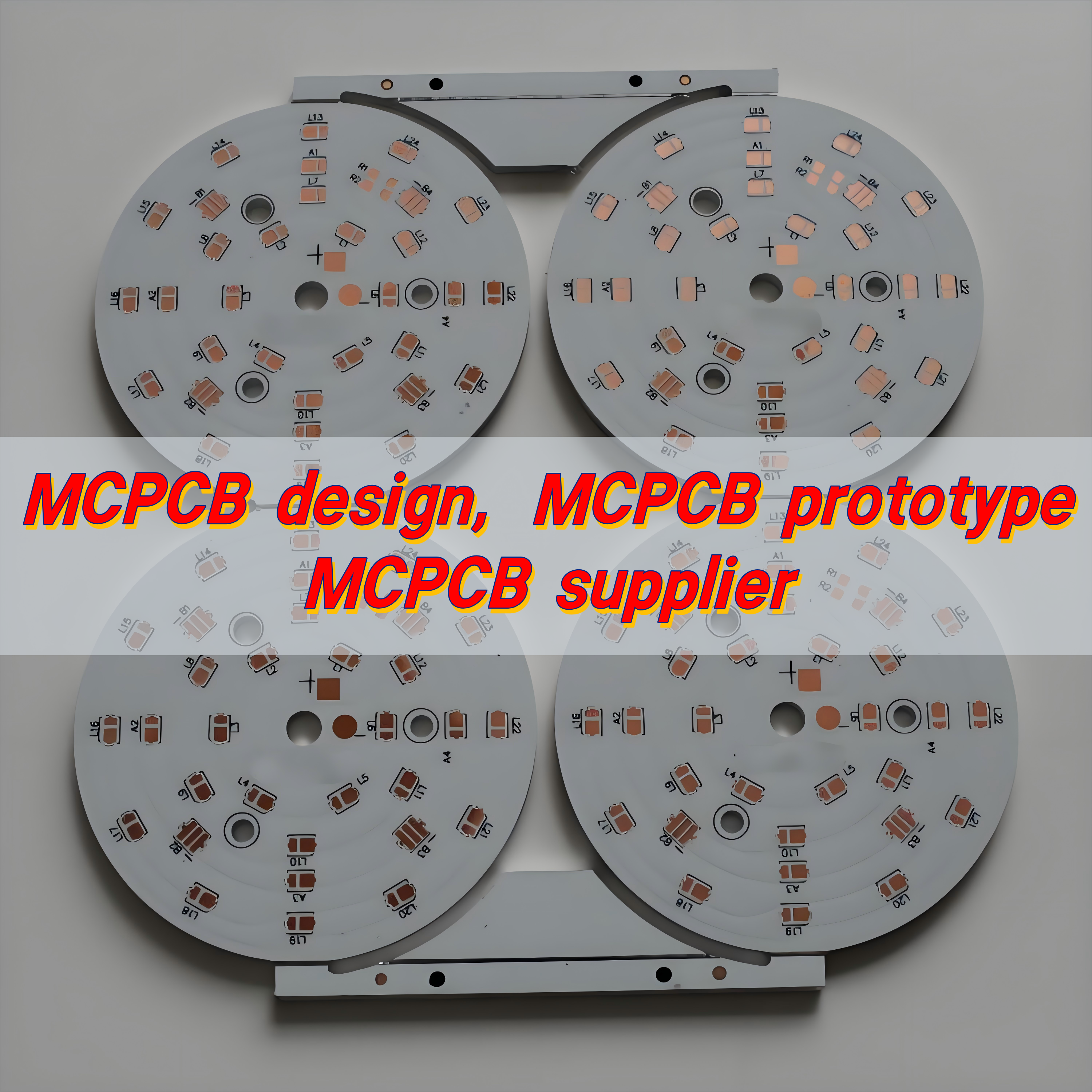
EBest delivers this balance by optimizing every step of our manufacturing process from material selection to production efficiency to eliminate unnecessary costs, without compromising on quality. We source high-grade aluminum substrates and conduct strict quality checks, ensuring our PCBs meet the harsh demands of motorcycle riding.
Our bulk supply capabilities further enhance value, offering stable pricing and on-time delivery for large projects. This consistency means you avoid unexpected cost hikes or delays, while getting a durable, high-performance motorcycle LED light aluminum PCB that delivers long-term reliability at a fair price.
Extreme Weather Riding: Can Your LED Light PCBs Take the Heat and Rain?
Extreme weather from scorching desert heat and heavy downpours to freezing mountain temperatures—poses a unique challenge for Motorcycle LED Light Aluminum PCB. Unlike on-road riding, outdoor and off-road adventures expose PCBs to unforgiving conditions that test their durability, and a subpar PCB will fail when you need reliable lighting most.
When it comes to withstanding extreme heat, motorcycle LED light aluminum PCB outperforms traditional substrates by leaps and bounds. Its aluminum core, with a thermal conductivity of 200-237 W/mK, dissipates heat far faster than FR4 PCBs (which only have 0.2-0.4 W/mK), preventing LED overheating even in 100°F+ desert rides. This avoids component warping or solder joint failure that plagues low-quality PCBs in high temperatures.
For heavy rain, mud, or even snowmelt, our Aluminum PCBs are paired with IP67-rated conformal coatings that seal every trace and solder joint. This protection blocks moisture from seeping into the PCB, eliminating short circuits and corrosion, common issues that render traditional PCBs useless after exposure to wet extreme weather.
EBest’s Motorcycle LED Light Aluminum PCB also resists thermal shock, the sudden temperature changes that occur when riding from hot deserts to cold mountain passes. Its well-matched thermal expansion coefficient with copper foil prevents insulation peeling, ensuring consistent performance in all extreme weather, so your LED lights stay bright and reliable no matter the conditions. Unlike FR4 PCBs that have a thermal resistance of 20–22 °C per watt, our aluminum PCBs only have 1–2 °C per watt, making them far more resilient in harsh environments.
Comparing PCB Materials: Why Aluminum Wins for Motorcycle LEDs
| PCB Material | Thermal Conductivity (W/mK) | Vibration Resistance | Waterproof Compatibility | Suitability for Motorcycle LEDs |
| Aluminum | 200-237 | High | Excellent (with coating) | Best |
| FR4 | 0.2-0.4 | Low | Poor | Not Recommended |
| Copper | 401 | Medium | Good | Expensive, Less Practical |
| Flexible PCB | 1-2 | High | Medium | Limited Thermal Performance |
Where to Find High-Performance Aluminum PCBs for Your Motorcycle LED Project?
High-performance aluminum PCBs are critical for motorcycle LED systems, delivering superior heat dissipation, vibration resistance, and long-term reliability in harsh riding conditions. Whether building headlights, turn signals, accent lights, or high-power auxiliary LEDs, choosing the right source ensures stable performance, longer LED life, and compliance with automotive-grade standards. Below are targeted, actionable channels and suppliers to source reliable aluminum PCBs tailored to motorcycle LED projects.
- Specialized Automotive & LED PCB Manufacturers: Focused vendors with IPC-A-600 Class 2/3 certification, optimized thermal dielectric layers (1.0–3.0 W/m·K), and white solder mask for maximum light reflectivity, ideal for high-power motorcycle LEDs.
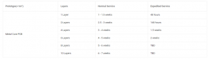
- Global B2B Manufacturing Platforms (Alibaba, Made-in-China): Access vetted aluminum PCB factories with rapid prototyping, custom profiles, and motorcycle-specific design support; filter by thermal conductivity, copper weight (1–4 oz), and vibration-rated production.
- North American PCB Fabricators: Domestic/regional suppliers offering fast turnaround, strict quality control, and design-for-manufacturing (DFM) checks for U.S./EU motorcycle projects, with full material traceability.
- European MCPCB Specialists (ICAPE Group, Laird Technologies): Premium suppliers providing high-thermal-performance aluminum substrates (T-Lam, VT‑4 series) engineered for automotive vibration, temperature cycling, and road‑worthy durability.
- Online Rapid Prototyping Services: Quick-turn aluminum PCB providers for small‑batch testing and custom LED layouts; support cut-to-size shapes, thermal vias, and double‑sided aluminum designs for compact motorcycle housings.
- Motorcycle Aftermarket & Lighting Component Distributors: Specialized distributors offering pre-engineered aluminum PCB modules for headlights, taillights, and LED strips, with plug‑and‑play compatibility for common bike models.
- Custom EMS (Electronics Manufacturing Services) Providers: Full‑service partners that deliver aluminum PCB fabrication + SMT assembly + conformal coating, creating fully tested LED assemblies ready to install on motorcycles.
- Industrial Metal Core PCB (MCPCB) Factories in Asia: High-volume, cost-effective manufacturers with mature aluminum PCB lines for LED lighting, capable of scaling from prototypes to mass production for fleet or aftermarket brands.
- Online Electronics Marketplaces (Digi‑Key, Mouser): Stocked standard aluminum PCB boards and base materials for hobbyists and small builders, with quick shipping and datasheet transparency for thermal and electrical specs.
- Direct Custom Fabrication from Experienced PCB Manufacturers: Work directly with factories to specify aluminum thickness, dielectric type, copper weight, and environmental protection (salt‑spray, UV‑resistant) for extreme riding conditions.
FAQs About Motorcycle LED Light Aluminum PCB
Q1: How long does a Motorcycle LED Light Aluminum PCB last?
A1: A high-quality Motorcycle LED Light Aluminum PCB typically lasts 5+ years with regular outdoor use. EBest’s PCBs are tested for durability and can withstand harsh riding conditions, extending their lifespan even further.
Q2: Can Aluminum PCBs for motorcycle LEDs be customized for small light housings?
A2: Yes. EBest offers fully customized motorcycle LED light aluminum PCB, including thin designs (0.8-1.2mm) to fit tight light housings. We work with your specifications to ensure a perfect fit for any motorcycle LED project.
Q3: Are Aluminum PCBs waterproof enough for heavy rain?
A3: Yes. Our motorcycle LED light aluminum PCB features an IP67 waterproof coating and sealed solder joints, protecting against heavy rain, mud, and moisture. They are tested to withstand prolonged exposure to water without damage.
Q4: Do Aluminum PCBs reduce LED overheating in motorcycle lights?
A4: Absolutely. Aluminum PCBs have high thermal conductivity (200-237 W/mK), which quickly transfers heat away from LED chips. This reduces overheating by 40% on average, preventing LED burnout and extending light lifespan.
Q5: Can Aluminum PCBs handle off-road vibration?
A5: Yes. EBest’s motorcycle LED light aluminum PCB undergoes strict vibration testing (10-2000Hz, 10g acceleration) to ensure they can handle off-road and rough terrain. Their rigid aluminum base absorbs vibration and keeps components secure.