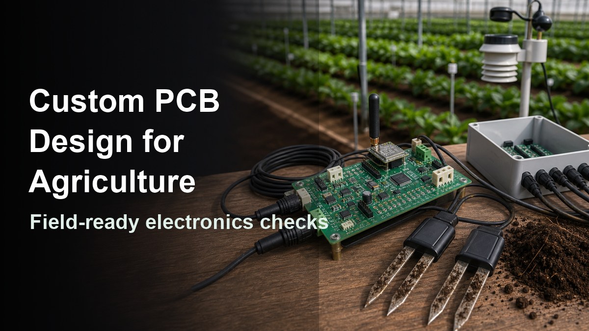
Custom PCB design for agriculture means designing a circuit board that can survive moisture, dust, vibration, unstable power, long cable runs, sensor drift and outdoor service conditions. A board used inside a soil sensor, irrigation controller, greenhouse monitor, livestock tracker or farm machine is not just a normal indoor PCB with a different enclosure.
The safest approach is to design the PCB, enclosure, connectors, power input, sensor interfaces, wireless layout and test plan together. If these decisions are left until production, the project may pass a bench test but fail after rain, washing, temperature cycling, fertilizer exposure or field vibration.
What Does Custom PCB Design for Agriculture Need to Solve?
Agriculture PCB design must solve environmental exposure and measurement reliability at the same time. The board may need to read weak sensor signals, run from battery or solar power, communicate wirelessly, drive pumps or valves, and keep working in wet, dusty and electrically noisy locations.
For a farm device, the PCB is often part of a larger field system. The same board may connect to soil probes, temperature sensors, humidity sensors, GPS modules, LoRa, NB-IoT, Bluetooth, motor drivers, solenoids or user controls. That mix creates real trade-offs: sensor accuracy needs clean analog layout, wireless modules need controlled antenna space, and outdoor wiring needs surge and reverse-polarity protection.
This is why the design review should start from the use case, not only from the schematic. A greenhouse data logger, a drip irrigation controller and a tractor-mounted control module can all be called agriculture electronics, but their PCB risks are different.
| Application | Main PCB design concern | What to confirm before RFQ |
| Soil and moisture sensor node | Low-noise sensing, waterproof cable entry, battery life | Sensor type, probe connector, coating or potting limits |
| Irrigation controller | Valve current, relay or MOSFET heat, surge protection | Load current, cable length, transient protection and enclosure plan |
| Greenhouse monitor | Humidity, condensation, wireless stability | Operating temperature, antenna position and conformal coating area |
| Farm machine electronics | Vibration, wide input voltage, connector strain | Mounting method, power input range, harness and test standard |
| Livestock or asset tracker | Battery life, RF performance, mechanical size | Battery chemistry, sleep current target, antenna keep-out area |
Which Field Conditions Change Agriculture PCB Design?
Moisture, dust, chemicals, temperature swing, vibration and unstable power are the conditions that most often change agriculture PCB design. If the board is specified like an office device, the first field failure may come from corrosion, connector leakage or a power transient rather than from the core circuit.
Humidity and condensation are common in greenhouses, irrigation cabinets and outdoor sensor boxes. If moisture can reach the PCB surface, high-impedance sensor circuits may drift and exposed copper may corrode. Designers should decide early whether the board needs conformal coating, selective coating keep-out zones, potting, sealed connectors or a vented enclosure.
Dust, mud and fertilizer residue can create another problem: they trap moisture and make cleaning difficult. Connector position, enclosure drain paths and service access matter. A connector that works in a lab may become a failure point if it faces upward, sits near a water path or lacks strain relief.
Power input also needs attention. Agricultural equipment may use long cable runs, solar charging, batteries, vehicle power or shared power rails. The PCB may need reverse-polarity protection, input filtering, surge suppression, brownout behavior and enough copper width for valve or motor loads. For material selection and base board planning, the FR4 printed circuit board page is a useful internal reference for common FR4 PCB options.
How Should Sensors, RF and Power Be Planned?
Sensors, RF and power should be planned as three interacting systems, not separate blocks. A low-power wireless agriculture board may fail if the antenna is blocked by the enclosure, if the sensor trace runs beside a switching node, or if the battery rail collapses during transmission.
Start with the sensor interface. Soil probes, pH probes, temperature sensors, flow meters and pressure sensors may use analog voltage, resistance, frequency, I2C, SPI, UART, RS-485 or other interfaces. Weak analog signals need short routing, guard spacing where needed, stable references and a quiet ground strategy. Digital sensors need connector mapping, ESD protection and firmware-accessible diagnostics.
Wireless planning should be handled before the mechanical layout is frozen. LoRa, Wi-Fi, Bluetooth, NB-IoT and cellular modules each need antenna clearance, ground reference, keep-out areas and sometimes matching components. If the enclosure is metal, wet or mounted near machinery, RF performance may change. The article on IoT sensor PCB assembly is a related page for sensor modules, wireless devices and PCBA test planning.
Power design should match how the device will really be used. A solar-powered field node may care most about sleep current and battery charging safety. An irrigation controller may care about surge protection and load current. A machine-mounted PCB may need wider input voltage tolerance, filtering and vibration-resistant connectors. Put current paths, heat sources and sensitive sensor traces in different layout zones when possible.
What Materials and Protection Choices Matter?
Material and protection choices matter because agriculture electronics often fail at the boundary between PCB, enclosure and environment. FR4 may be suitable for many projects, but the design still needs the right copper weight, solder mask coverage, surface finish, coating decision and mechanical support.
For many sensor boards and controllers, standard FR4 is a practical starting point. High Tg FR4, heavier copper, rigid-flex construction, aluminum PCB or ceramic PCB may be considered when temperature, current, bending, heat spreading or size constraints justify them. Do not choose a special material only because the application sounds harsh; choose it because the electrical, thermal or mechanical requirement makes it necessary.
Protection should be discussed with the manufacturer before assembly. Conformal coating can protect against moisture and residue, but it may interfere with connectors, test pads, switches, LEDs, sensor membranes or calibration points. Potting can improve sealing and vibration resistance, but it can make rework impossible and trap heat. A gasketed enclosure helps, but the PCB still needs proper connector orientation and creepage/clearance decisions.
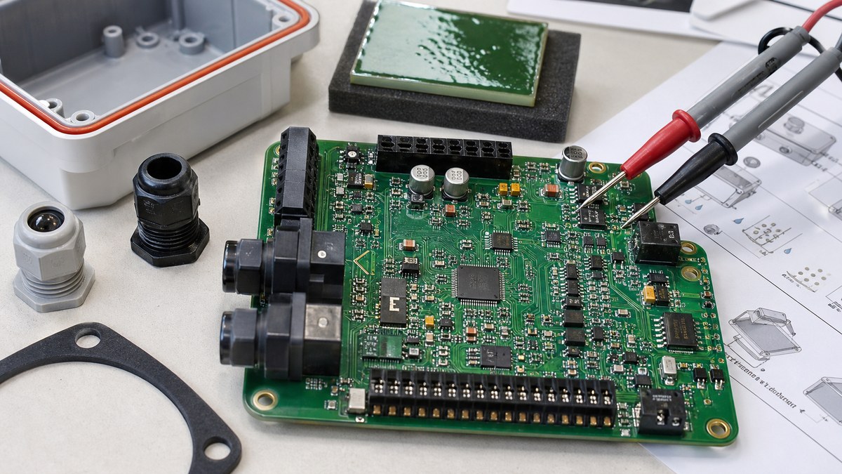
If the device will face rain, spray, condensation or washing, compare the enclosure plan with PCB-level protection. The waterproof PCB guide explains coating, potting and protection trade-offs that are especially relevant to farm electronics.
How Should Connectors, Enclosures and Assembly Be Specified?
Connectors, enclosures and assembly should be specified before the PCB layout is released. In agriculture devices, many failures start at cable entry points, unsupported connectors, difficult assembly steps or missing test access.
Use locking or sealed connectors where field wiring is exposed to vibration, splash or repeated service. Place connectors so cables can be strain relieved and routed without sharp bends. If the device needs field replacement, the connector choice should match what a technician can handle with gloves, dust and limited visibility.
The enclosure affects PCB shape, mounting holes, connector height, antenna position, cable glands and service access. If the board needs a conformal coating process, mark coating keep-out areas in the drawing. If it needs potting, confirm component height, heat dissipation and whether any part must remain exposed to air.
Assembly files should not be treated as an afterthought. A clean BOM, centroid file, polarity notes, programming instructions, coating notes and test requirements reduce mistakes. For PCBA planning, the PCB assembly and SMT service page is the relevant service page to link when the article discusses prototype or production assembly.
What Testing Should Be Done Before Field Use?
Testing should prove that the PCB works electrically and that the field risks have been addressed. For agriculture electronics, a simple power-on test is not enough if the product will face moisture, vibration, long cables, battery sag or wireless range limits.
Start with normal manufacturing tests: visual inspection, AOI where applicable, continuity checks, programming, functional test and current consumption measurement. Add application-specific tests such as sensor calibration, wireless transmission, load switching, sleep current, input overvoltage behavior, reverse-polarity response and connector continuity after cable movement.
Environmental and mechanical validation depends on the project risk. A prototype may need humidity exposure, temperature cycling, splash simulation, vibration checks or enclosure sealing review. These tests should be defined with realistic limits rather than vague wording such as “outdoor grade.” If no formal standard is specified, record the actual test condition in the engineering notes.
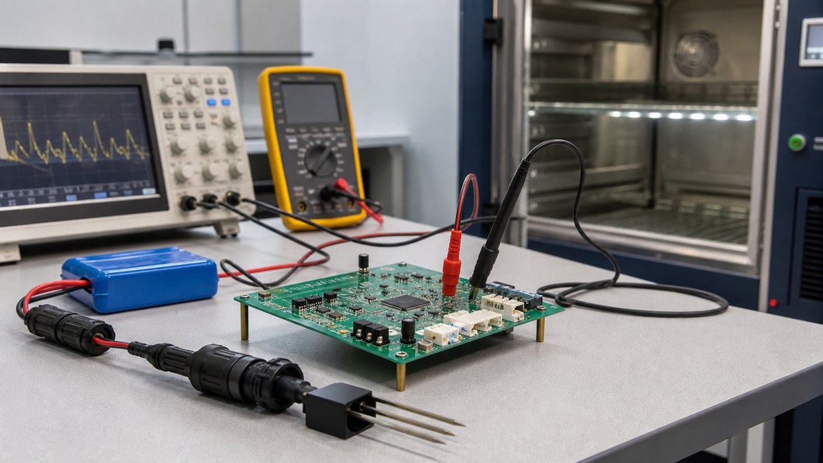
When writing the RFQ, include the required inspection method instead of assuming the supplier will infer it. The PCB test equipment page can support sections about inspection capability, while the custom PCB board fabrication guide is useful for file, stackup and process-check details before quotation.
Agriculture PCB Design Checklist for RFQ Files
A good RFQ package should let the PCB manufacturer understand the electrical design, field environment, assembly process and validation requirements. Missing environmental or test details often lead to a cheaper quote that does not match the real project risk.
- Gerber or ODB++ files, drill files, board outline and stackup notes.
- Schematic or design notes for sensor inputs, power input and communication interfaces.
- BOM, centroid file, polarity notes and approved substitutes if assembly is required.
- Material preference, copper weight, surface finish and solder mask requirements.
- Enclosure drawing, mounting hole position, connector height and cable exit direction.
- Coating, potting or no-clean requirements, including keep-out zones.
- Operating temperature range, humidity exposure, splash/dust exposure and vibration concern.
- Programming, calibration, current consumption and functional test requirements.
- Prototype quantity, pilot quantity, mass production estimate and expected revision plan.
- Any standards, customer test methods or acceptance criteria that must be followed.
If the agriculture device uses long cables, wireless modules, battery power or outdoor enclosures, send mechanical and use-case information early. The PCB supplier can review DFM, panelization, assembly handling and test access only if those details are visible before fabrication.
FAQ About Custom PCB Design for Agriculture
What is custom PCB design for agriculture?
Custom PCB design for agriculture is the process of designing a circuit board for farm, greenhouse, irrigation, livestock, sensor or machinery electronics. It must consider the circuit function and the field environment together, including moisture, dust, vibration, power input, connectors, sensor accuracy and testing.
Can a normal PCB be used in agricultural electronics?
A normal FR4 PCB can be used in many agriculture devices, but only if the design also handles enclosure sealing, connector protection, coating or potting needs, power input risk and test access. The problem is usually not the word “FR4”; it is whether the board was designed for field exposure.
What sensors are common in agriculture PCB projects?
Common sensors include soil moisture, temperature, humidity, light, pH, pressure, flow, GPS, accelerometers and gas sensors. The PCB layout should match the sensor interface. Analog sensors need noise control, while digital and wireless sensor modules need connector, ESD and firmware test planning.
Does an agriculture PCB need conformal coating?
It depends on the exposure level. Coating is useful for humidity, condensation and light contamination, but it should not cover connectors, switches, some sensors, programming pads or calibration areas. Decide coating zones before assembly, not after the finished PCB already has access problems.
What power problems affect agriculture electronics?
Battery sag, solar charging variation, long cable voltage drop, reverse polarity, pump or valve transients and vehicle power spikes can all affect agriculture PCBs. The design may need input filtering, TVS protection, fusing, reverse-polarity protection, brownout handling and enough copper width for load current.
How should wireless modules be placed on farm device PCBs?
Wireless modules should be placed with the antenna keep-out area, enclosure material, ground reference and cable locations in mind. A module that works on a bench may lose range inside a metal box, near wet soil, beside a battery pack or under a poorly positioned cable harness.
What files should I send for an agriculture PCB quote?
Send Gerber or ODB++ files, drill data, board outline, stackup, BOM, centroid file, enclosure drawing, connector information, coating or potting notes, environmental conditions, test requirements and expected quantities. If the project includes firmware loading or calibration, include those instructions too.
Is potting better than conformal coating for farm electronics?
Potting can provide stronger sealing and vibration support, but it can trap heat and prevent rework. Conformal coating is lighter and easier to inspect, but it does not seal the whole product. The right choice depends on moisture exposure, service needs, heat and mechanical stress.
How can buyers reduce prototype risk?
Build the first prototype with test points, connector access, programming access and clear environmental notes. Test power input, sensor reading, wireless range, current consumption and enclosure sealing before mass production. Do not wait for a large batch to discover that a connector, antenna or coating zone is wrong.
Should agriculture PCB design be handled before or after enclosure design?
It should be handled together with enclosure design. Board outline, antenna location, connector direction, gasket pressure, cable strain relief, coating keep-outs and service access all depend on the enclosure. Treating the enclosure as a late packaging step often creates avoidable redesign.
Final Supplier Notes for Agriculture PCB Projects
Agriculture electronics are usually judged in the field, not only at the lab bench. A good custom PCB design for agriculture should make the sensor readings stable, the wireless link practical, the power input protected, the connectors serviceable and the production test clear.
Before ordering, review the field environment, enclosure, cable harness, coating plan, power input and test requirements with the PCB supplier. If you are sourcing custom PCB design, PCB fabrication or PCB assembly for agriculture sensors, irrigation controllers, greenhouse devices or farm equipment, send your files and field requirements to our engineering team for DFM review and quotation at {contact_email}.