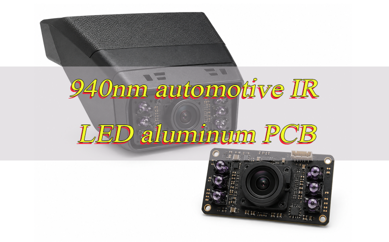
A 940nm automotive IR LED aluminum PCB is used in automotive camera illumination systems such as driver monitoring and occupant monitoring, where 940nm IR LEDs provide low-visible-glow illumination for cameras operating in low-light conditions. Its performance depends on camera sensitivity, IR radiant output, pulsed current, thermal resistance, LED placement and optical uniformity, so these factors must be evaluated together during PCB design, assembly and validation.
Are you facing these problems in a 940nm automotive IR LED aluminum PCB project?
- IR output does not match the camera: The selected 940nm LEDs appear powerful enough, but the camera image is still dark or inconsistent.
- Temperature rises more than expected: Peak current is acceptable on paper, but repeated pulses create excessive temperature at the LED or PCB.
- Prototype illumination cannot be repeated easily: LED position, orientation, soldering or component variation changes the illumination pattern between builds.
As a professional one-stop PCB and PCBA service provider, EBest Circuit supports automotive IR LED aluminum PCB fabrication, component sourcing, PCB assembly, prototyping and mass production. Our solutions include:
- Match illumination to the actual camera: Review sensor response, optical transmission, FOV and emitter characteristics before defining the required IR output.
- Verify the real pulse load: Peak current must be reviewed together with pulse width, duty cycle, repetition rate and operating temperature.
- Control what affects production consistency: The released LED part number, footprint, orientation, placement and assembly requirements should remain controlled from prototype through production.
Developing a 940nm automotive IR LED aluminum PCB? Send the PCB files, BOM, IR LED part number and operating conditions to sales@bestpcbs.com for manufacturing review.
Why Is a 940nm Automotive IR LED Aluminum PCB Used for Camera Illumination?
A 940nm automotive IR LED aluminum PCB is used when a camera illumination module needs low-visible-glow IR output, pulsed LED operation, heat transfer and controlled emitter positioning. Current 940nm automotive IR LEDs are specifically offered for driver monitoring, occupant monitoring, interior monitoring, gesture sensing and child-presence detection.
- Reduced visible red glow: 940nm produces substantially less visible red glow than 850nm, which is useful when illumination operates inside a dark vehicle cabin.
- Low-light camera illumination: 940nm emitters provide near-infrared illumination for camera-based in-cabin sensing when available visible light is insufficient.
- High-current pulse operation: Automotive IR emitters can be designed for short high-current pulses. The allowable current depends on pulse width, duty cycle and temperature rather than a single current rating.
- Thermal management: Heat generated at the emitter must pass through the LED package, solder interface and PCB into the mechanical heat-spreading structure.
- Controlled LED positioning: Automotive 940nm emitters are available with circular, rectangular and tilted radiation patterns, so component position and rotation directly affect the illuminated field.
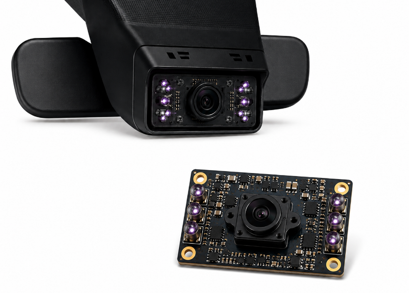
How Do Camera Sensitivity and Optical Filters Affect 940nm IR LED Radiant Power?
The required 940nm radiant output depends on how much usable infrared energy reaches the image sensor after losses through the optical system.
- Sensor sensitivity at 940nm: Higher NIR quantum efficiency increases the camera response for a given amount of incident 940nm energy. Sony’s IMX775 shows that automotive sensors can be specifically optimized for this wavelength.
- Lens transmission: The lens must transmit sufficient energy around the selected NIR wavelength.
- Optical filters: IR-pass, band-pass or other filters can attenuate part of the 940nm energy before it reaches the sensor.
- Protective covers: Dark camera windows or trim materials can introduce additional NIR transmission loss.
- Working distance: As the illuminated field expands, the same radiant output is distributed over a larger area.
- Target reflectivity: Skin, fabric and other cabin surfaces do not return the same amount of NIR energy to the camera.
- Exposure conditions: Camera exposure and synchronization with the LED pulse influence how much reflected IR is captured.
- Beam pattern: Narrow, wide, rectangular and tilted emitters distribute the available radiant output differently.
Electrical wattage should not be used as an optical-output specification. The SFH 4728BS A01 T1 datasheet separately specifies parameters such as radiant intensity and optical characteristics under defined operating conditions.
How Do Peak Current, Pulse Width and Duty Cycle Define the Load on a 940nm IR LED Aluminum PCB?
Peak current defines only the highest instantaneous current. Pulse width, duty cycle, repetition rate and operating temperature determine how the LED and PCB experience that load over time.
- Peak current: Maximum current carried during each IR pulse.
- Pulse width: Duration of the high-current event.
- Duty cycle: Percentage of time the LED remains energized.
- Repetition frequency: How frequently the pulse repeats.
- Forward voltage: Together with current, determines instantaneous electrical input.
- Simultaneous LED count: Multiple emitters operating together increase total board and connector current.
- Operating temperature: Permissible pulse current changes as component temperature rises.
The SFH 4728BS A01 T1 specifies 1.5A maximum forward current and up to 5A pulsed forward current only when tp ≤ 10ms and D ≤ 0.25. Its permitted operating current also varies with pulse and thermal conditions.
For a 940nm IR LED aluminum PCB, specify the complete pulse profile rather than only a maximum current value.
How Should Thermal Resistance Be Controlled in a Pulsed 940nm Automotive IR LED Aluminum PCB?
Thermal resistance must be controlled across the complete path from the LED junction to the housing. The aluminum base is only one part of that path.
For a conventional single-layer aluminum IMS, the thermal path is typically:
LED junction → package thermal pad → solder joint → copper circuit layer → thermally conductive dielectric → aluminum base → thermal interface/contact → housing or heat spreader
Insulated metal substrates are specifically used to reduce thermal impedance and conduct heat from high-watt-density surface-mount assemblies.
Control the thermal path by:
- Maintaining the LED thermal pad area: Follow the released package footprint instead of reducing the heat-transfer area for routing convenience.
- Controlling the solder interface: Poor wetting, insufficient solder or excessive voiding beneath the thermal pad can increase interface thermal resistance.
- Maintaining the approved PCB construction: The dielectric lies directly in the heat path, so an unapproved change in construction can alter thermal performance.
- Controlling PCB-to-housing contact: Poor flatness or incomplete mechanical contact adds another thermal interface.
- Controlling TIM where used: Excessive thickness or trapped air can reduce effective heat transfer.
- Testing with the actual pulse conditions: Thermal verification should reproduce the specified current, pulse width, duty cycle and ambient condition.
The SFH 4728BS A01 T1 specifies a maximum junction temperature of 145°C and a junction-to-solder-point thermal resistance of 3.9K/W typical and 4.7K/W maximum. These are component values, not the thermal resistance of the complete PCB and housing assembly.
How Should 940nm IR LED Placement and Beam Angle Match the Automotive Camera FOV?
LED placement should provide sufficient illumination across the camera’s horizontal and vertical FOV at the intended working distance.
- Define the camera FOV: Use the actual horizontal and vertical field that requires illumination.
- Define the working-distance range: Check coverage at relevant near and far positions.
- Account for camera-to-LED offset: LEDs positioned beside the camera do not share the same optical axis.
- Match beam pattern to the field: A rectangular camera field may be better matched by a rectangular IR emitter.
- Control component orientation: Rectangular and tilted emitters require the correct PCB rotation.
- Reference LEDs to mechanical datums: LED position should remain aligned with the camera and housing during final assembly.
Current automotive 940nm IR products include 60°, 80°, 150°, 110° × 135° and 130° × 155° beam patterns, together with tilted-emission variants.
The correct beam is the one that covers the required camera FOV with adequate irradiance, not simply the widest available emitter.
How Can a 940nm IR LED Array Reduce Hot Spots and Improve Illumination Uniformity?
Uniform illumination depends on LED spacing, beam overlap, emitter orientation and working distance.
- Reduce center hot spots: Avoid concentrating the high-intensity centers of several beams in the same area.
- Improve edge coverage: Review LED position and beam shape when the outer FOV receives insufficient illumination.
- Prevent dark gaps: Adjacent emitters should provide adequate overlap at the intended working distance.
- Use asymmetric beams where appropriate: Rectangular or tilted emitters can direct more energy toward areas that a circular beam covers inefficiently.
- Control LED rotation: Orientation errors can shift rectangular or tilted patterns away from the required field.
- Balance independent channels where available: Current adjustment can help correct some illumination imbalance, provided each emitter remains inside its specified limits.
- Measure across the FOV: Optical validation should evaluate several positions across the camera field rather than only the optical center.
Automotive 940nm emitters with 110° × 135° and 130° × 155° rectangular patterns are already available for in-cabin sensing, showing that beam geometry is an application-level design parameter.
Adding more LEDs is not automatically an improvement; poor beam overlap can create stronger hot spots while also increasing current and heat.
What PCB Layout Details Matter for High-Current 940nm Automotive IR LED Arrays?
The PCB layout must carry the pulse current while preserving the LED thermal connection and optical position.
- Current path: Route for the real peak current and simultaneous LED load, not only average current.
- Compact pulse loop: Keep driver-to-LED and return paths short to reduce unnecessary resistance and parasitic inductance.
- Branch consistency: Avoid unnecessary differences in path resistance between comparable LED branches.
- Exact LED footprint: Use the released manufacturer’s land pattern.
- Thermal pad connection: Preserve the intended thermal-contact area of the package.
- Connector path: Include connector and cable resistance when the LED driver is located off-board.
- Sensitive reference paths: Keep high di/dt LED current away from sensitive sensing or control references.
- Optical orientation: Tie LED rotation to the camera or housing datum.
- Temperature sensing: Position temperature sensors where they support the intended thermal-control or protection method.
The SFH 4728BS A01 T1 is supplied with package-specific dimensional and solder-pad requirements, reinforcing the need to design around the exact released emitter rather than a generic high-power LED footprint.
What Manufacturing and Assembly Controls Matter for a 940nm Automotive IR LED Aluminum PCB?
Manufacturing should reproduce the approved PCB construction, IR LED part number and optical geometry from prototype through production.
Step 1: Verify the released project files
Confirm the Gerber or ODB++, BOM, pick-and-place file, assembly drawing, exact IR LED ordering code, polarity, rotation and critical dimensions.
Step 2: Verify the LED footprint
Compare the land pattern with the current LED datasheet. For rectangular or tilted emitters, verify both electrical orientation and optical direction.
Step 3: Manufacture the approved PCB construction
Build according to the released copper, dielectric, aluminum base, surface finish, dimensions and mechanical tolerances. Review any proposed construction change before production.
Step 4: Control solder paste and placement
Control paste deposition, component centering and LED rotation because they affect solder quality, thermal contact and optical position.
Step 5: Follow LED handling and reflow requirements
The selected emitter’s current datasheet should control footprint, handling and reflow requirements. The cited SFH 4728BS family includes defined assembly requirements and package-specific solder information.
Step 6: Inspect the finished assembly
Check LED polarity, orientation, placement, solder condition and electrical operation. Perform thermal or optical verification when those acceptance limits are included in the project specification.
The SFH 4728BS A01 T1 also defines separate radiant-intensity groups, so the approved ordering code or permitted optical group should remain controlled when production uniformity depends on binning.
What Automotive Reliability Requirements Apply to a 940nm IR LED Camera Illumination Board?
Automotive reliability should be separated into component qualification and finished-module validation.
- IR LED qualification: AEC-Q102 covers failure-mechanism-based stress-test qualification for discrete optoelectronic semiconductors used in automotive applications.
- Component evidence: The current SFH 4728BS A01 T1 is identified by ams OSRAM as AEC-Q102 qualified.
- Finished PCB validation: Qualification of the emitter does not qualify the assembled aluminum PCB.
- Environmental requirements: The final camera illumination assembly may require temperature, cycling, vibration, power-cycling or other validation according to the vehicle program.
- Traceability: PCB revision, BOM revision, IR LED ordering code and production-lot information should remain controlled when required by the project.
AEC-Q102-qualified LED ≠ AEC-Q102-qualified PCB assembly.
AEC-Q102 applies to the optoelectronic semiconductor component, not the complete 940nm automotive IR LED aluminum PCB.
How Should a 940nm Automotive IR LED Aluminum PCB Be Tested for Electrical, Thermal and Optical Performance?
A finished 940nm automotive IR LED aluminum PCB should be tested under actual or representative camera-module operating conditions.
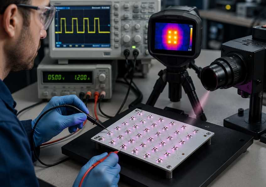
- Electrical performance: Check LED polarity, continuity, forward voltage, peak current, pulse width, duty cycle and repetition frequency. Measure the LED pulse waveform where the project requires waveform verification.
- Thermal performance: Operate the board at the specified peak current, pulse width and duty cycle. Measure temperature at defined locations such as the LED solder area, aluminum base and housing interface. Compare the result with the selected emitter’s temperature limits.
- Optical output: Where radiant output is specified, measure it using a defined current waveform, working distance and detector position.
- Camera FOV coverage: Verify illumination across the required horizontal and vertical field, including the edges and corners.
- Illumination uniformity: Measure IR intensity across multiple positions to identify center hot spots, dark edges and gaps between LED beams.
- LED-to-LED consistency: For multi-LED arrays, check for abnormal differences caused by current variation, optical binning, component placement or assembly.
- Board-to-board consistency: Compare representative production boards under the same drive and measurement conditions when optical consistency is part of the acceptance requirement.
- Camera-level performance: When required, operate the board with the intended camera and verify the defined low-light image performance.
- Test-condition control: Record ambient temperature, supply voltage, peak current, pulse width, duty cycle, working distance and camera or detector position so test results remain comparable.
- Photobiological safety where applicable: If the finished IR source requires safety evaluation, IEC 62471 provides exposure limits, measurement methods and classification guidance for electrically powered incoherent optical sources, including LEDs, from 200nm to 3000nm.
Why Choose EBest Circuit for 940nm Automotive IR LED Aluminum PCB Manufacturing?
For a 940nm automotive IR LED aluminum PCB project, the approved PCB, IR LED and assembly data need to remain consistent from prototype through production. EBest Circuit supports PCB fabrication, component sourcing and PCB assembly within its stated service scope.
- Reduce coordination between PCB and assembly suppliers: PCB fabrication, component sourcing and PCB assembly can be handled within the same service scope, reducing unnecessary transfers of BOM, PCB revision and assembly information.
- Keep the specified 940nm IR LED under BOM control: The customer-approved part number can remain tied to the released BOM rather than being treated as a generic 940nm emitter. This matters when beam pattern, package, optical-output group or pulse rating affects the finished module.
- Carry prototype requirements into production: EBest Circuit supports PCB prototyping and mass production, allowing the approved PCB revision, footprint, orientation and assembly data to remain controlled as the project moves forward.
- Support automotive manufacturing requirements: EBest Circuit’s supplied company information lists IATF 16949 and ISO 9001:2015 among its certifications.
- Metal-based PCB manufacturing experience: Metal Core PCB is included in the company’s stated PCB product range, and EBest Circuit was founded in 2006.
- Project-specific manufacturing review: Gerber or ODB++ files, LED footprint, BOM, placement data and pulse conditions can be reviewed against the released project requirements rather than replaced with generic aluminum PCB recommendations.
What Files and Specifications Are Required for a 940nm Automotive IR LED Aluminum PCB Quote?
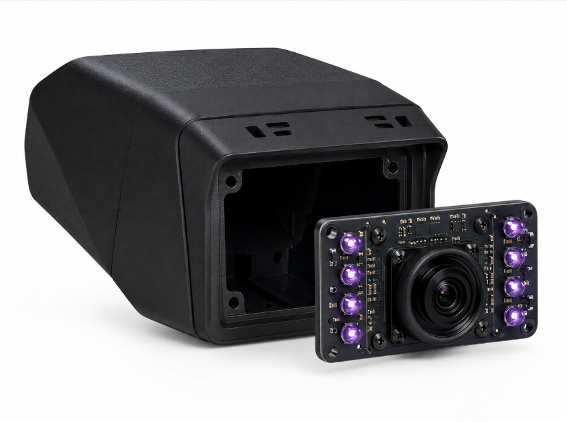
For an initial 940nm automotive IR LED aluminum PCB quote, provide the PCB files, assembly data and actual IR LED operating conditions. Add thermal or optical acceptance requirements when they form part of the manufacturing scope.
PCB Fabrication Files
- Gerber or ODB++ files
- NC drill files
- Fabrication drawing
- Board dimensions and mechanical drawing
- Approved PCB construction
- Copper thickness
- Surface finish
- Critical dimensions and tolerances
- Prototype or production quantity
PCB Assembly Files
- BOM
- Pick-and-place file
- Assembly drawing
- Exact 940nm IR LED manufacturer and part number
- LED datasheet
- Polarity and orientation requirements
- Approved alternatives, if applicable
IR LED Operating Conditions
- Supply voltage
- Peak LED current
- Pulse width
- Duty cycle
- Repetition frequency
- Number of LEDs operating simultaneously
- Driver or test-interface information where functional testing is required
Optical and Thermal Requirements
Provide these when applicable:
- Camera FOV
- LED beam pattern
- Working distance
- Required illumination area
- LED position or rotation tolerance
- Radiant-output requirement
- Illumination-uniformity requirement
- Thermal test conditions and temperature limits
- Camera-level functional test criteria
If some specifications are still being finalized, the available Gerber or ODB++ files, BOM, LED part number and pulse conditions are sufficient to begin an initial manufacturing review.
FAQs About 940nm Automotive IR LED Aluminum PCBs
The question topics below were selected from recurring community discussions about 850nm versus 940nm camera compatibility, IR visibility, IR-cut filters, beam coverage and external IR illumination on Reddit and other electronics communities. The technical answers are based on device or standards information rather than community claims.
Q1: Can a camera that works with 850nm IR also work with a 940nm illuminator?
A1: Compatibility depends on the image sensor and complete optical path. A camera may detect both wavelengths but have substantially different sensitivity at each. Before moving from 850nm to 940nm, check the sensor spectral response and filter transmission. Sensors can also be optimized specifically for 940nm; Sony’s IMX775 specifies 35% QE at 940nm.
Q2: Why can the same 940nm illuminator look much brighter on one camera than another?
A2: The result depends on the sensor’s 940nm response, lens and filter transmission, exposure conditions and camera processing. The same IR source can therefore produce different image brightness on different cameras. Evaluate the LED with the intended production camera, not by LED wattage alone.
Q3: Is a 940nm IR LED completely invisible?
A3: It is safer to describe 940nm as having very low visible red glow rather than guaranteeing absolute invisibility. ams OSRAM describes 940nm as virtually invisible with only slight red glow, while community users also report that faint emission can still be noticeable under some dark-viewing conditions.
Q4: Does LED binning matter in a multi-LED 940nm array?
A4: Binning matters when the application requires controlled optical output between LEDs or production boards. The SFH 4728BS A01 T1, for example, is supplied with defined radiant-intensity groups. Control the approved ordering code or permitted bin range when optical consistency is part of the specification.
Q5: Can a narrower 940nm LED beam improve useful illumination distance?
A5: A narrower radiation pattern concentrates more of the available radiant output within a smaller angular field, while a wider pattern distributes it across a larger field. The correct choice should therefore balance irradiance and required camera FOV, not distance alone. Current automotive 940nm products range from relatively narrow patterns to 150° and rectangular 130° × 155° options.
Q6: Can a 940nm IR LED be driven far above its continuous-current rating if the duty cycle is low?
A6: Only within the pulse limits stated in the exact LED datasheet. Permitted peak current depends on pulse width, duty cycle and temperature, not duty cycle alone. The SFH 4728BS A01 T1 permits up to 5A pulsed current only under defined pulse conditions, while its continuous-current limit is lower.
Q7: Can an IR-cut filter prevent a camera from using 940nm illumination?
A7: A camera will receive less 940nm energy if its optical filter has low transmission at that wavelength, even when the image sensor itself has useful NIR sensitivity. This is why the sensor response and optical-filter transmission must be reviewed together before changing the IR wavelength.
Q8: Can one 940nm IR LED be replaced by another 940nm part without changing the PCB or optical design?
A8: The same nominal wavelength does not make two LEDs interchangeable. Parts can differ in package dimensions, solder pad, beam pattern, optical output, thermal resistance and pulse-current limits. ams OSRAM’s current 940nm automotive range alone includes 50°, 60°, 80°, 150°, rectangular and tilted-emission versions.
Q9: Should IR eye safety still be evaluated when 940nm light is difficult to see?
A9: Visible brightness is not a valid measure of infrared exposure. Where photobiological safety assessment is required, the complete source should be evaluated according to its radiant output, geometry and exposure conditions. IEC 62471 includes LEDs within its framework for incoherent optical-source safety.
Q10: What should be checked when prototypes work but production boards show different IR illumination?
A10: Compare the exact LED ordering code, permitted radiant-intensity group, drive waveform, LED rotation, XY placement, solder condition and camera alignment. Electrical continuity alone does not verify optical consistency. The SFH 4728BS A01 T1 datasheet itself defines different radiant-intensity groups, showing why component ordering information can matter in production.
A reliable 940nm automotive IR LED aluminum PCB must maintain the specified pulse current, heat path, emitter position and illumination geometry from prototype through production.
EBest Circuit provides metal-based PCB manufacturing, PCB prototyping, component sourcing, PCB assembly and mass-production services. Send your PCB files, BOM, IR LED data and operating requirements to sales@bestpcbs.com for manufacturing review and quotation.