A solder blow hole is a surface opening left when gas escapes through molten or partly solidified solder, most often in a plated through-hole (PTH) joint after wave soldering or selective soldering. The gas may come from PCB moisture, damaged hole-wall plating, trapped flux, or blocked venting, while an unsuitable thermal profile can make any of these problems worse. This guide shows how to recognize the defect, trace it to the PCB or soldering process, judge its reliability risk, and prevent it without relying on guesswork or repeated touch-up.
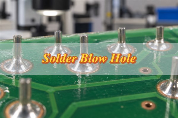
What Is a Solder Blow Hole?
A solder blow hole is a gas-created cavity that opens at the surface of a solder joint. Heat turns moisture, trapped air, flux solvent, or contamination into gas. If that gas enters the PTH while the solder is liquid, it can push through the fillet and leave a crater as the joint solidifies.
A blow hole is not the same as every solder void. A void can remain fully enclosed, while a blow hole has a visible surface opening. Incomplete vertical fill is also a separate condition. When the cavity cannot be seen clearly, use X-ray or a cross-section before deciding what is inside the joint.
What Does a Blow Hole Look Like in a Solder Joint?
Look for a round or irregular crater in the solder fillet, often with a dark center whose bottom is not visible. It commonly appears beside a through-hole lead on the solder side, even when the surrounding solder looks properly wetted.
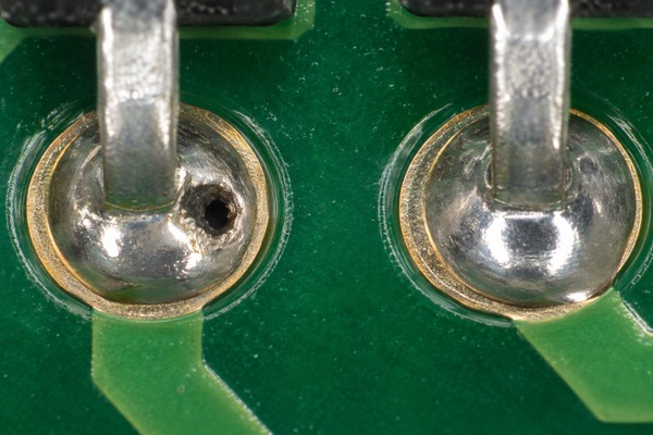
- Opening: A crater or pin-sized hole in the fillet, not an unfilled annular area.
- Location: Beside the lead, near the barrel wall, or at the fillet edge.
- Pattern: Repeated on one component, hole family, board area, or PCB lot.
- Related signs: Solder splash, incomplete fill, laminate damage, lifted lands, or poor wetting.
A photograph confirms the surface feature, not its depth. Map where the openings occur, then use the pattern and internal inspection to choose the first root-cause check.
What Causes Blow Holes in Solder Joints?
A blow hole needs three things: a gas source, a path into the joint, and molten solder. Common sources and paths include:
- PCB moisture: Absorbed water becomes steam during soldering.
- PTH defects: Resin cavities, debris, pinholes, cracks, or uneven copper trap gas or open a route through the barrel wall.
- Flux or contamination: Excess flux, unevaporated solvent, or residual chemistry releases gas at wave contact.
- Blocked venting: A low component body, collar, tight lead fit, or mask intrusion closes the easier top-side exit.
- Thermal imbalance: Poor preheat leaves moisture or solvent in the hole; excessive heat can stress weak plating.
- Joint geometry: Hole clearance, board thickness, copper planes, and component orientation affect heating, fill, and gas escape.
The defect pattern narrows the cause. A single PCB lot or repeated hole location points toward board construction; a defect that starts after one recipe change across several lots points toward the assembly process.
Why Are Through-Hole Solder Joints More Prone to Blow Holes?
A PTH joint traps gas more easily because the lead, copper barrel, laminate, flux, and rising solder share a narrow vertical space. As solder climbs the annular gap, it can seal the solder-side opening. If a low-mounted component also covers the top, expanding gas may be forced back through the liquid solder.
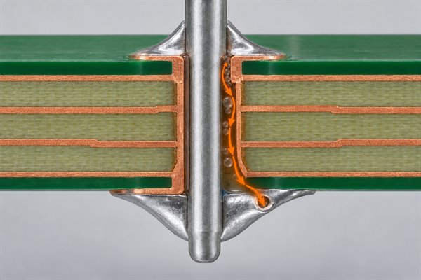
PTHs also place copper and laminate together under rapid heating. Weak adhesion, drilling damage, or discontinuous plating can open a gas path as the materials expand. Check component seating, lead-to-hole clearance, top-side venting, and barrel condition before changing the soldering recipe.
How Does PCB Moisture and Outgassing Lead to Blow Holes?
Moisture causes a blow hole when it becomes vapor faster than it can escape safely. Water absorbed during storage or handling can pressurize the heated PTH region and travel through a plating defect into molten solder. Residual fabrication chemistry, contamination, and trapped flux solvent can produce the same effect.
- Compare properly stored and exposed boards from the same PCB lot.
- Run one material-approved drying trial without changing components, flux, or the soldering recipe.
- If defects remain, inspect barrel plating, resin cavities, and trapped process chemistry.
A lower defect rate after drying supports moisture as a contributor, but it does not prove the barrel is sound. Avoid arbitrary bake conditions that may damage solderability, labels, components, or laminate materials.
Which Wave Soldering Conditions Can Increase Blow Hole Formation?
Wave soldering conditions increase risk when moisture or flux volatiles reach the wave before they are removed, or when heating and solder contact trap gas inside the PTH.
- Insufficient or uneven preheat: Cool areas retain moisture or solvent and may fill poorly.
- Excess or uneven flux: Liquid left in the hole releases gas during wave contact.
- Incorrect speed, angle, or contact time: These settings change heat transfer, hole fill, and venting time.
- Unbalanced solder temperature: Too little heat can weaken fill; too much can stress the laminate and barrel.
- Uneven thermal mass: Ground planes, thick boards, heavy copper, and large connectors create local cold spots.
- Top-side obstruction: Low-seated parts can seal the vent path.
Measure the affected joint with thermocouples, change one variable within the qualified window, and recheck fill, wetting, bridging, and component temperature. If the same verified change corrects several PCB lots, the process hypothesis becomes stronger.
How Can PCB Hole Design and Plating Affect Blow Hole Risk?
Hole geometry controls solder flow and venting; barrel quality controls whether gas can enter through the hole wall.
- Finished-hole clearance: Too little restricts flux, solder rise, and venting; too much can weaken capillary fill. Compare the lead maximum with the finished-hole tolerance, not the drill size.
- Barrel integrity: Rough drilling, smear, resin cavities, thin copper, pinholes, cracks, or poor adhesion can store gas and create an escape path.
- Component seating: A body, shoulder, or collar against the top pad can cap the hole. Verify the intended standoff.
- Thermal connections: Heavy planes can keep one hole cooler. Review thermal relief, copper balance, and solder access.
Review the finished-hole drawing, lead tolerance, seating detail, and a representative microsection together. If dimensions are in tolerance but the same barrel location keeps failing, investigate drilling and plating before adding heat or widening the hole.
Do Solder Blow Holes Affect Solder Joint Reliability?
A blow hole can affect reliability, but the surface opening alone does not show how serious it is. A shallow crater may leave adequate wetted area. A deeper cavity can reduce mechanical area, hide incomplete fill, or indicate a plating defect that grows under thermal cycling.
Base the disposition on:
- cavity depth and connection to the barrel;
- vertical fill and circumferential wetting;
- lead, land, and plating condition;
- mechanical, electrical, vibration, and thermal demands; and
- the governing standard, drawing, product class, and customer criteria.
Continuity at room temperature does not prove mechanical integrity. Quarantine the affected population and decide whether to accept, rework, or reject only after the internal evidence and acceptance criteria agree.
How Should Solder Blow Holes Be Inspected and Evaluated?
Start with a defect map, then choose solder joint inspection methods that answer the remaining internal questions.
- Inspect both sides: Record the designator, opening location, component, PCB lot, and defect frequency.
- Check the complete joint: Review wetting, vertical fill, lead protrusion, land condition, splash, bridging, and laminate damage.
- Use angled X-ray when needed: Oblique or 2.5D views can reveal PTH fill and voiding that a surface image cannot, although overlapping features may limit simple 2D X-ray.
- Cross-section representative samples: A microsection can show cracks, plating continuity, resin cavities, separation, and the connection between the crater and an internal void.
- Correlate records: Compare storage history, PCB lots, flux application, measured profiles, wave settings, and defect locations.
- Apply the agreed criteria: Record the current standard revision, product class, drawing requirements, customer specification, and disposition.
A complete inspection record contains the affected population, evidence of the joint’s internal condition, and a disposition tied to the governing criteria.
How Can You Tell Whether the Blow Hole Comes From the PCB or the Soldering Process?
Use repeated patterns and controlled comparisons; one photograph cannot assign the cause.
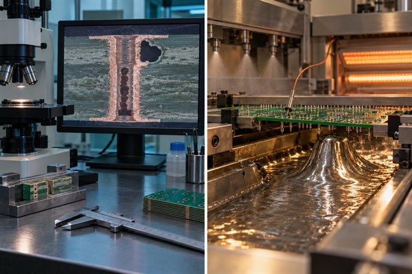
- One PCB lot or the same hole location fails: Suspect laminate, drilling, plating, local contamination, or design. Compare bare-board coupons, microsections, and supplier lot records.
- Several PCB lots fail after one recipe change: Suspect preheat, flux, conveyor, wave settings, or handling. Compare measured profiles and machine records from before and after the change.
- Only low-seated components fail: Suspect blocked top-side venting. Check standoff, collars, shoulders, orientation, and hole clearance.
- Controlled drying helps but does not eliminate the defect: Moisture contributes, but a structural gas path may remain. Inspect the barrel and resin for cavities or cracks.
- Defects follow heavy copper or cool zones: Suspect local thermal imbalance. Profile an affected joint and a known-good joint on the same board.
Hold the PCB lot, component lot, flux, and recipe constant except for the factor being tested. Use defect-rate changes to narrow the hypothesis, then confirm the gas path with X-ray or a representative cross-section.
How Can You Prevent Solder Blow Holes Before and During Assembly?
Prevent blow holes by controlling the PCB barrel, moisture exposure, venting, and soldering window before production begins.
- Define geometry and acceptance: Lock finished-hole and lead tolerances, board thickness, component seating, venting, solder access, and governing criteria.
- Control bare-board quality: Qualify drilling, desmear, cleaning, and plating; use coupons or microsections where the risk justifies them.
- Protect stored boards: Follow approved packaging, storage, and exposure limits. Dry boards only with a documented, material-compatible procedure.
- Qualify flux, preheat, and wave together: Verify flux coverage and solvent removal with a measured board profile, then set the wave parameters inside the approved process window.
- Trend production: Map defects by PCB lot, component, hole family, and recipe before the issue becomes a large rework population.
- Verify the corrective action: Compare controlled groups and confirm the next build with inspection or cross-section evidence when required.
The corrective action should remove the gas source, close abnormal paths into the barrel, or restore a safe venting and soldering window. If the defect returns, reopen the root-cause investigation instead of making touch-up routine.
FAQs About Solder Blow Holes
Q1: Does a switch from HASL to ENIG prove that the surface finish caused the blow holes?
A1: No. The change may coincide with different storage, hole geometry, wetting, or supplier processing. Compare controlled lots and inspect the barrel before assigning the cause to ENIG.
Q2: Can raising a low-seated LED or connector reduce recurring blow holes?
A2: Yes, if the body or collar seals the top of the PTH. Use an approved standoff change, then verify mechanical stability, lead length, and solder fill.
Q3: Will nitrogen eliminate solder blow holes?
A3: Not by itself. Nitrogen may improve wetting and reduce oxidation, but it cannot remove moisture, repair porous plating, evaporate excess flux, or open a blocked vent.
Q4: Why can blow holes cluster on ground pins while nearby signal pins remain normal?
A4: Ground pins often connect to more copper and heat more slowly. Compare thermal profiles and thermal-relief geometry at affected and normal pins.
Q5: Should suspect joints be touched up before failure analysis?
A5: Keep representative joints untouched. Rework can alter the crater, drive off volatiles, add flux, or damage the land and barrel. Photograph and map samples first.
Q6: Which records should be frozen when the defect is first found?
A6: Preserve PCB and component lots, storage history, flux and alloy batches, machine recipe, measured profile, defect map, two-sided images, and any X-ray or microsection results.
In short, a blow hole is the symptom; the right correction depends on whether the evidence points to PTH structure, moisture or venting, or the soldering process.
For a recurring defect or a new PTH design, send EBest Circuit your Gerber or ODB++ data, stackup, hole and lead dimensions, defect map, PCB lot history, and thermal profile at sales@bestpcbs.com for an engineering review and PCB/PCBA quotation.