





A furnace circuit board does far more than switch the heat on and off. It reads thermostat and safety inputs, controls the blower or ignition hardware, reports faults, and operates beside relays, transformers and field-wiring terminals.
Those mixed control, power and mechanical demands shape the PCB material, copper, component layout, SMT/THT assembly and testing plan. The sections below explain what needs close control during a prototype build, what should be frozen before volume production, and what information makes a manufacturing review useful.
What Is a Furnace Circuit Board and What Does It Control?
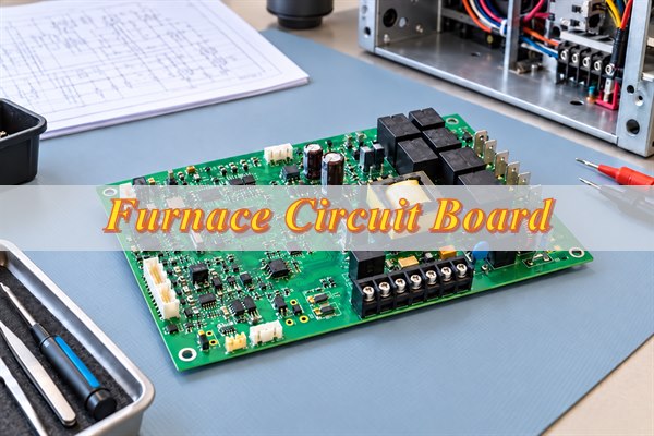
A furnace circuit board is the electronic controller that receives heat-demand and safety signals, then coordinates the outputs that run a forced-air furnace. It connects the thermostat, safety switches, blower controls, indicators and other devices defined by the furnace design.
The board first reads inputs such as thermostat calls, temperature sensors, limit switches and pressure switches. Its control logic checks those states in the required sequence before it energizes a relay or another output.
On a gas-furnace design, the same board may also control the inducer, ignition circuit and gas valve while monitoring the flame signal. An electric furnace uses a different load and safety arrangement, so the two designs should not share an assumed I/O map.
During operation, the board can show status or faults through LEDs, error codes or a communication interface. The production package therefore needs the real connector pinout, controlled loads, safety inputs, board variant and firmware, not only a generic “furnace control board” description.
What Components Are Used on a Furnace Circuit Board?
A furnace circuit board normally combines a controller, power supply, relays, connectors and safety-signal interfaces on one assembly. The relays, transformer and field terminals distinguish it from a small all-SMT controller because they add weight, heat and larger solder joints.
| Component Type | Function | Assembly Checks |
| Control IC or microcontroller | Runs timing, operating logic, diagnostics and communication | Orientation, package match and programming requirement |
| Relays and output switches | Switch blowers, valves, igniters or auxiliary loads | Part number, mounting direction and solder quality |
| Transformer and power components | Provide voltage conversion, isolation or regulated rails | Pin match, mechanical support and solder-joint quality |
| Connectors and terminal blocks | Connect incoming power, thermostat wiring, sensors and controlled loads | Part number, orientation and full seating |
| Safety and sensor interfaces | Condition limit, pressure, temperature, flame or other input signals | Polarity, package and placement in the correct circuit area |
The relays, transformer and terminals deserve the closest assembly review. Their lead size, thermal mass and insertion force can affect hole fit, solder fill and board stress, so the approved part numbers, footprints and support method should match before the first build.
How Do You Choose Materials and Copper Thickness for a Furnace Circuit Board?
Choose the laminate, copper weight and board thickness from the conditions at the PCB. Actual board temperature, continuous and startup current, permitted temperature rise, mounting method and insulation requirements are more useful than the furnace enclosure temperature alone.
- Material heat resistance: Use the specified or measured board temperature and the local temperature around hot components. Put required flammability or material recognition on the fabrication drawing.
- Copper thickness: Evaluate continuous current, startup current and allowed temperature rise. Treat the trace, vias, solder joints and terminal as one current path.
- Board thickness: Match the mounting points, enclosure and connectors while supporting relays, transformers and repeated terminal use.
- Insulation spacing: Base clearances on working voltage, transients, environment and applicable product requirements. Coating should not hide an unresolved spacing problem.
These decisions are connected: heavier copper can change etching and thermal behavior, while a thicker board can change connector fit and lead protrusion. EBest can review manufacturability and suggest build options, but the customer approves the electrical ratings, spacing and thermal design.
How Are Furnace Circuit Boards Assembled?
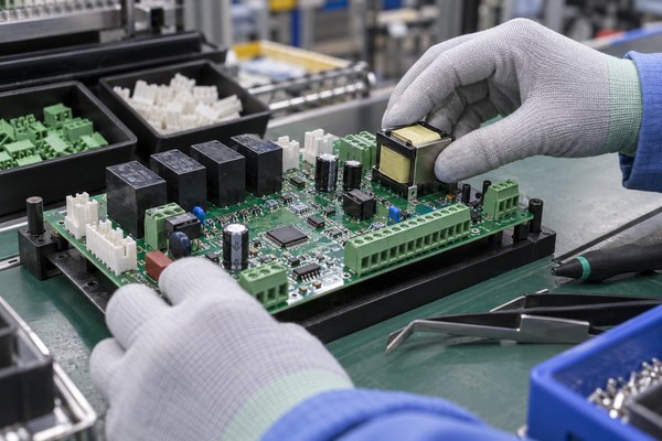
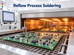
Furnace circuit boards are usually assembled with a mixed SMT and through-hole process. The SMT controller and support parts are reflowed first; relays, transformers and terminals are then inserted, supported and soldered under conditions suited to their greater mass.
Step 1: Match the build files. Check the PCB revision, BOM, placement data, assembly drawing and DNP list before materials are issued.
Step 2: Assemble the SMT side. Print solder paste, place the control ICs and supporting parts, then reflow and inspect the SMT joints.
Step 3: Install the heavy parts. Verify the orientation and seating of relays, terminal blocks and transformers. Add the specified clips, adhesive or hardware before soldering.
Step 4: Control through-hole soldering. Check large joints for wetting and hole fill. Keep residue away from high-voltage separation areas and sensitive signal circuits.
Step 5: Finish the correct board variant. Load the specified firmware, apply the matching label and mask connectors, test points and no-coat areas before conformal coating.
The completed PCBA should show which hardware and firmware version was built and whether every heavy component and high-current joint passed inspection. That record links the approved prototype to the next production batch.
How Are Furnace Circuit Boards Inspected and Tested?
Inspection confirms assembly quality; functional testing confirms that the board responds correctly. A furnace board can look acceptable yet still miss a safety input, carry the wrong firmware or fail to switch a load, so workmanship checks alone are not enough.
| Method | What It Checks | When It Is Used |
| Visual inspection | Part presence, orientation, terminal seating, visible joints and board condition | All assembled boards to the agreed criteria |
| AOI | SMT presence, alignment, polarity and visible solder features | According to the assembly process and component layout |
| X-ray | Hidden joints or selected solder conditions | When package structure or a specified joint requires internal inspection |
| Programming verification | Device programming, firmware version and supported readback or checksum | For programmed board variants |
| Electrical or functional test | Specified rails, inputs, outputs, indicators, communication and sequences | When a fixture, test steps, loads and limits are available |
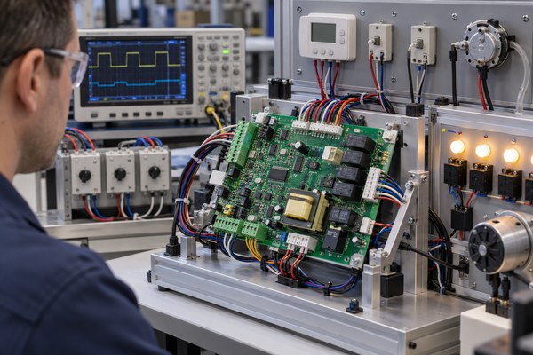
A board-level test can cover the following functions when the fixture and pass limits are defined:
- Power: Confirm input behavior and the required power rails.
- Inputs: Verify thermostat, limit-switch, pressure-switch or other simulated signals.
- Outputs: Check relays or other outputs under the specified conditions and loads.
- Diagnostics: Confirm indicator LEDs, fault codes or communication responses.
- Configuration: Match the firmware version to the correct board variant.
- Gas-furnace functions where applicable: Exercise the specified ignition sequence, simulated flame signal and abnormal-input response.
Every functional check needs a fixture connection, simulated signal, load and pass/fail limit. These results verify the agreed board behavior; they do not replace validation of the complete furnace.
What Should You Check Before Ordering Furnace Circuit Boards in Volume?
Before volume production, freeze the exact design that passed prototype or pilot approval. A hand-reworked sample, an old quotation package or an unrecorded firmware change is not a reliable production baseline.
- Approved sample: Record which prototype or pilot unit was accepted and what it proved.
- Closed changes: Incorporate approved layout changes, BOM substitutions, DNP updates, firmware corrections and coating changes into the released revision.
- Production version: Give each board variant a clear PCB, BOM, firmware and label identity.
- First volume lot: Set the first-article or first-batch checks before normal release.
- Delivery control: Confirm batch identification, packaging and the records needed for later quality or repeat-order review.
When the sample, files, firmware, labels and acceptance checks all point to the same revision, the first production lot can be judged against a known baseline instead of becoming another prototype experiment.
What Affects Furnace Circuit Board Cost and Lead Time?
Furnace circuit board cost and lead time depend on the complete build, not board size alone. PCB construction, component availability, mixed assembly, coating, programming and functional-test time can each change the quotation.
| Cost or Schedule Factor | What Changes the Work |
| Quantity and PCB construction | Prototype setup, panel use, layer count, laminate, copper weight, thickness and surface finish |
| Component supply | Specified brands, availability, minimum order quantities, customer-supplied parts and approved alternatives |
| Mixed assembly | SMT plus relays, transformers, terminals, mechanical support and manual operations |
| Coating | Masking, application, curing and coating inspection |
| Programming, testing and records | Firmware handling, fixture preparation, simulated loads, test time, report detail and traceability requirements |
A released BOM and a defined test scope remove the largest pricing unknowns. If a relay, transformer or controlled-brand component has a long procurement lead, that part can set the delivery date even when the bare PCB is straightforward.
Why Choose EBest Circuit for Furnace Circuit Board Manufacturing and Assembly?
EBest Circuit coordinates PCB fabrication, component sourcing and PCBA assembly through one manufacturing path. This reduces file handoffs and keeps the bare board, BOM, firmware and test requirements tied to the same revision.
- PCB manufacturing and assembly through one contact: Reduce schedule and file coordination across separate suppliers.
- SMT/THT mixed assembly: Build control ICs, relays, terminal blocks, transformers and other through-hole parts on the same PCBA.
- Free DFM review: Find footprint, hole-size, polarity and assembly-data conflicts before production setup.
- Project-defined programming and testing: Match firmware and inspection records to the agreed board variant.
- 15-year traceability: Support batch lookup, quality investigation and repeat-order comparison.
The result is a single controlled build package from PCB fabrication through final board checks. That makes prototype changes, batch questions and repeat orders easier to trace without separating the PCB history from the assembly record.
What Files Are Required for a Furnace Circuit Board Quote?
A furnace circuit board quote starts with the PCB data, BOM, assembly data, quantity and target date. These files specify what will be fabricated, which parts will be fitted and how much production capacity the build requires.
Basic quotation files: These establish the board, fitted parts and requested order.
- PCB data: Gerber or ODB++ data and drill files.
- Component data: BOM with manufacturer part numbers where specified.
- Assembly data: Pick-and-place file and assembly drawing.
- Order information: Required quantity and target delivery date.
Provide these items when they apply: They affect programming, coating, testing or delivery.
- Programming: Firmware file, board-variant mapping and programming instructions.
- Coating: Coating requirement and masking drawing.
- Testing: Test procedure, fixture information, simulated inputs, loads and pass/fail limits.
- Delivery: Special packaging, labeling, traceability or report requirements.
If some details are still open, send the files already available and mark the missing items. The DFM review can then separate the information needed for an accurate quote from the decisions that can be closed before production release.
FAQs About Furnace Circuit Board Manufacturing and Assembly
Q1: Can I order bare furnace PCBs without assembly?
A1: Yes. EBest can quote bare PCB fabrication without component sourcing or assembly. Send the Gerber or ODB++ data, drill files, quantity and required board construction.
Q2: Can you assemble boards using customer-supplied bare PCBs?
A2: Yes, after the supplied boards and assembly package pass a manufacturability review. The PCB finish, solderability, panel format, quantity and storage condition must suit the planned assembly process.
Q3: Can I start with a small prototype batch before volume production?
A3: Yes. A prototype or small pilot batch can verify assembly, programming and the agreed board-level test before volume production. Record any rework or substitution so it is included in the production revision.
Q4: Can assembled boards be supplied without programming?
A4: Yes. Assembled boards can be supplied without programming. Mark programming as not required in the quotation package. If some variants are programmed and others are not, give each version a clear part number and label.
Q5: Can customers supply some or all components?
A5: Yes. Customers can supply selected parts or the complete component kit. Identify each supplied part in the BOM and confirm its part number, quantity and delivery condition. Extra units may be needed for setup or normal assembly attrition.
Q6: Can specified component brands be used?
A6: Yes. List the exact manufacturer and part number for every brand-controlled component. Mark parts that allow no substitution. Brand restrictions can affect availability, minimum order quantity and lead time.
Q7: How are DNP components handled?
A7: Mark every DNP position in both the BOM and assembly drawing. For multiple board variants, provide a controlled population list for each version.
Q8: Can several board variants be included in one order?
A8: Yes, when each variant has a separate build identity. State its quantity, BOM or DNP list, firmware status and label so one population or program cannot be applied to the wrong board.
Q9: Who provides the functional-test fixture?
A9: Fixture responsibility is confirmed after EBest reviews the test scope. Send the required test steps, simulated inputs, loads, connections and limits so the team can determine whether an existing customer fixture can be used or additional fixture work is feasible.
Q10: Can project files be protected under an NDA?
A10: Yes. An NDA can be discussed and signed before detailed project files are exchanged.
Conclusion
A reliable furnace circuit board build depends on three aligned decisions: how the PCB will be manufactured, which assembly operations are included, and what the board must pass before shipment. When those decisions match the approved revision, prototype results can carry into volume production.
Send your available design files, quantity and target delivery date to sales@bestpcbs.com to request a free DFM review and quotation.
You may also like


Tags: Furnace Circuit Board, Furnace Circuit Board Assembly, Furnace Circuit Board Cost, Furnace Circuit Board Manufacturing, Furnace Circuit Board Testing