PCB manufacturing PCB manufacturing
Home > Blog

VNA Port Extension

VNA Unknown Thru Calibration: When Ports Cannot Mate
Tuesday, November 17th, 2026

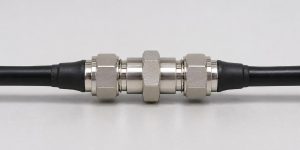
When your VNA test ports cannot mate, do not add a barrel and tell the analyzer it is a zero-length thru. The barrel can introduce loss, delay and mismatch. Use a properly defined thru, a suitable reciprocal Unknown Thru, or the instrument’s adapter-removal workflow. For an Unknown Thru, pass an independent amplitude and phase check before using the setup to judge an RF board.
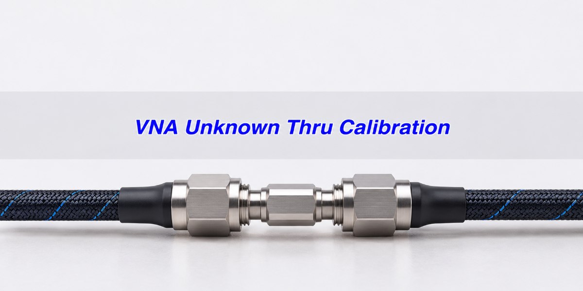
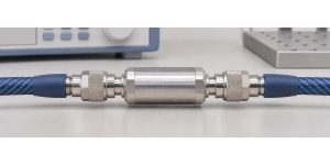
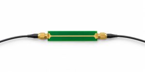
Machined coaxial through adapter joining two phase-stable VNA test cables
The thru is a temporary calibration connection. Document what remains on each test port when the board replaces it.

VNA Calibration: When the Test Ports Cannot Mate

Test ports are non-insertable in this setup if their mating ends cannot directly connect at the intended reference planes. Common examples include two same-sex connectors and two different connector families. The board may fit the two cables perfectly while the cables cannot mate with each other for a flush thru. Do not force the connection or mate connector interfaces that look similar but are not compatible. Confirm the interface, inspect the connectors and use the maker’s specified mating and torque procedure.

Draw the measured board, both mating faces and every adapter you plan to leave in place. The cut between test hardware and the board defines what the data will include. A calibration that verifies well at the wrong cut still describes the wrong network.

SOLR Calibration: What Does an Unknown Thru Solve?

In an Unknown Thru or SOLR calibration, establish the reflection standards at each port, then measure a reciprocal transmission connection in both directions. Rohde & Schwarz uses the name UOSM for a related unknown-through workflow. The instrument constrains the forward and reverse transmission of the thru to be equal as complex quantities (S21 = S12 under consistent references). The thru can still have loss and delay; its two reflections do not have to be identical.

It is the transmission connection that is “unknown,” not the port standards or setup. Follow the calibration wizard and use the appropriate standards at each port. Do not use an isolator, amplifier or other unverified directional device as the assumed reciprocal connection. Equality of magnitude at one frequency is not enough to establish reciprocity.

Adapter Removal Calibration vs. Unknown Thru vs. Defined Thru

Start with the standards you have and the planes the drawing requires. A suitable characterized thru can be the simplest choice; SOLR helps where an accurately defined thru is unavailable. If your platform cannot support SOLR with the required geometry, use a supported adapter-removal workflow or arrange an appropriate calibration kit.

Three choices for a non-insertable test setup
Method What you need Trade-off and check
Defined thru A compatible thru and its valid kit definition Check the actual standard and definition match. Do not substitute an unknown barrel for a flush standard.
Unknown thru (SOLR/UOSM) Suitable reciprocal path, correct port standards, sufficient received signal and supported phase-selection workflow The analyzer can resolve loss and delay without a full thru model, but verify the phase solution independently.
Adapter removal Compatible standards and supported calibration or characterization steps The classic two-calibration method needs more reconnections. Control repeatability and confirm the resulting planes.

Group Delay Measurement: Why the Thru Phase Estimate Matters

At 10 GHz, a quarter of a period is 25 ps, or 90°. Keysight’s cited M9485A workflow asks for the thru phase estimate to be within a quarter wavelength; refer to the actual instrument’s implementation. The estimate helps choose a phase solution; the two possible transmission solutions can differ by 180° without differing in magnitude. The quarter-cycle example does not mean the thru itself must have less than 25 ps of delay or that errors under 25 ps are acceptable for the final measurement.

In this ideal nondispersive example, an independently established thru delay is 145 ps. A 125 ps guess differs by 20 ps: |Δφ| = 360° × 10 GHz × 20 ps = 72°. A 110 ps guess differs by 35 ps, giving 126°. The latter is outside the quarter-cycle example. For an independently measured and nearly linear unwrapped phase trace, estimate one-way delay as −Δφ ÷ (360° × Δf), with frequency in Hz and phase in degrees. For dispersive media, where phase does not follow one constant delay across the band, follow the analyzer’s phase-selection procedure instead of entering a guessed coax delay.
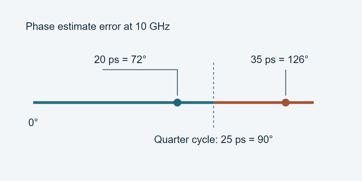
At 10 GHz, a delay estimate 20 ps off corresponds to 72 degrees and 35 ps off corresponds to 126 degrees
This is a calculation for phase-guess proximity, not an instrument accuracy chart or fabrication limit.

VNA Reference Plane: Set It Before Connecting the Thru

Set the frequency range, point count, power and any other settings required by the calibration workflow. Keep the cables in their measurement position. Capture the one-port standards at the actual intended mating faces, then connect the reciprocal thru and follow the wizard. Record the thru ID, connection orientation and delay or phase-selection setting. If a transition stays on the measurement cable, account for its location in the calibration design rather than silently moving it after verification.
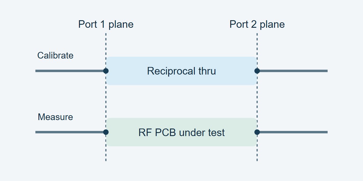
The same two VNA reference planes bound a temporary reciprocal thru and then the RF PCB under test
Use the same mating planes when the board replaces the thru. Adding or moving hardware can invalidate that assumption.

Check transmission through the chosen connection across the whole band. A deep notch near the receiver floor makes the estimate unreliable there. For example, Keysight cautions against 40 dB or more combined loss in the thru and calibration path on the cited workflow; use your instrument and measured signal rather than assuming 40 dB is universal. A plain VNA port extension may correct an accessible path’s delay, but it does not replace a two-port calibration that accounts for adapter mismatch.

Insertion Loss Measurement: Verify Phase, Not Just dB

Measure a separately characterized two-port that was not used to solve the calibration. Use the same frequency grid or a justified reference comparison, correct port order and specified impedance. Check both directions and compare phase as well as magnitude. When the application depends on return loss, verify the reflection response with a suitable independent mismatch standard too. The artifacts and results should cover the ranges that matter to the job. If that check must stay valid across a production run, use this VNA calibration drift guide to set checkpoint intervals and identify boards that need retesting.

Example release worksheet at 10 GHz; figures and limits are illustrative
Check Reference → indication Decision
Forward insertion loss 6.00 dB → 6.09 dB; error +0.09 dB Passes the example 0.15 dB magnitude-error limit, assuming the agreed uncertainty rule is satisfied.
Forward transmission phase −70° → −62°; difference +8° Fails the example 5° error limit. Hold calibration and review the settings and reference planes.
Reverse transmission and reseat Independent reverse reference plus readings after a controlled reconnect Required checks still open. Compare complex results to approved limits; neither earlier row releases the station.

Where Unknown Thru Helps on an RF PCB Bench

Same-sex ports on a coupon: Select a reciprocal thru that mates to the cables without forcing them into a new position. Qualify the setup in both directions before comparing coupon insertion loss or phase. Keep the board launches in the measurement unless your documented reference planes and separate fixture-removal method say otherwise.

Filter with mixed connector types: Use the correct reflection kit for each connector and a supported thru that mates both ends. Verify return loss and the loss and phase through the passband. Separately demonstrate usable receiver margin if stopband rejection is an acceptance requirement; a passband reference cannot by itself prove the stopband result.

Coax-to-waveguide fixtures: Use appropriate standards and a verified reciprocal transition. If the analyzer requires a dispersive phase selection, follow that process and verify with a distinct known connection over the operating band. Otherwise hold phase-sensitive conclusions.

VNA Calibration Procedure: What to Record Before Release

Record the analyzer and firmware, frequency grid, test settings, port connector types and planes, kit revision, thru ID and orientation, estimated delay or branch selection, and independent verification results. Include units and the governing decision rule. For troubleshooting, first inspect the raw receiver response and repeatable seating; then verify the cal kit and phase choice. Recheck the independent artifact after any change before retesting boards. A corrected plot that looks smooth is not evidence that the calibration passed.

VNA Unknown Thru Calibration FAQs

Does the Unknown Thru need to be lossless?

No. It must meet the instrument’s reciprocity, signal and phase-selection conditions. Its loss must leave enough received signal across the calibration band.

Can the Unknown Thru have different S11 and S22?

Yes. Reciprocity constrains the complex forward and reverse transmission under consistent references, not equality of the two reflection responses.

Can I enter a zero delay for a barrel?

Only when a procedure and verified phase range justify it as an estimate; do not define a real barrel as a perfect flush thru to avoid characterizing it.

Can I use the board itself as the Unknown Thru?

Some analyzers allow it if reciprocity, phase-selection and transmission conditions are met. Avoid using that same board as the only verification artifact.

Why does my loss pass but phase fail?

A magnitude check can miss a wrong phase branch or wrong plane. Check the phase against an independent known connection, then check connection repeatability.

Does a port extension remove adapter mismatch?

Not by itself. A phase or loss model does not recover the adapter’s full reflections and interaction with the device.

What if the two test ports use different connector families?

Use the correct standards for both connector families and a compatible thru or characterized transition within the instrument’s supported workflow.

When should I repeat verification?

Recheck when a cable moves substantially, a connector or adapter changes, a cal setting changes materially, or an independent reference fails. Use the approved interval for ongoing production checks.

Technical References

Custom RF PCBs With Stackup and Coupon Review

Need a custom RF PCB? Share your proposed stackup, layout and connector launches with EBest Circuit for review before fabrication. Include your operating band, impedance targets, coupon needs, quantity and delivery date. Send the files to sales@bestpcbs.com to request a project review and quotation.
You may also like

VNA Port Extension: Move the Plane, Check the Result
Tuesday, November 17th, 2026

VNA port extension moves the electrical reference plane past a section of transmission line. Use it when the section behaves like a nearly matched line with predictable delay. A flat phase trace after correction tells you that the fitted slope is gone. It does not tell you that the connector launch, fixture ripple or loss has been removed. If the two test ports cannot mate to establish the initial two-port calibration, see the VNA Unknown Thru calibration guide before making any port-extension correction.

For a two-port PCB fixture, enter the one-way delay at each port, not the round-trip delay measured on S11 or S22. Then measure a standard you did not use to fit the correction. If that check fails the phase or amplitude budget, stop and change the measurement method before signing off the DUT.

VNA Port Extension: What Actually Moves?

A reference plane is where the instrument reports the incident and reflected waves. If you calibrate at the coax connectors, a PCB launch and its feed line normally lie inside the measured network. If you want the response at the component pads instead, define the new planes at those pads. Moving the planes changes which electrical length you report; nothing physically moves. If the production spec is defined at the board’s connector, keep that connector in the result.

RF PCB test fixture with two coaxial launches and a device position between them
RF fixture illustration. Identify the connector planes and device planes separately on the actual fixture drawing.

For reflection, the wave goes down the test section and back along the same path. For transmission, it passes once through the section at each end. This is why one entry on port 1 affects S11 by twice its delay but S21 by only its one-way contribution. Compare data at the same planes and reference impedance; otherwise raw and corrected traces describe different networks.

VNA Port Extension Calculation: One-Way vs. Round-Trip Delay

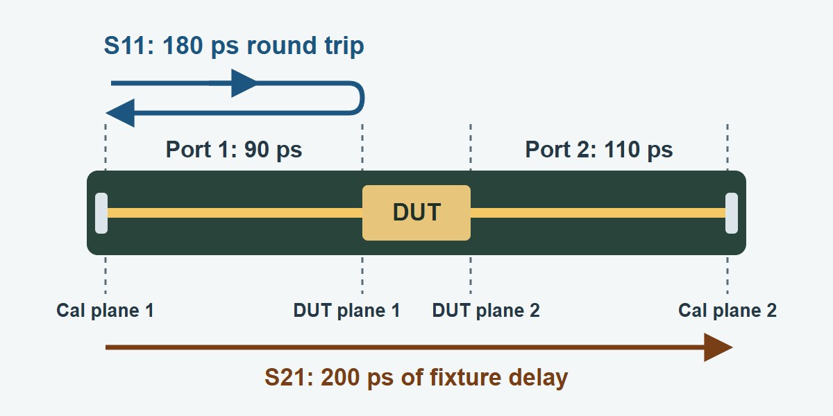
If the unwrapped S11 phase falls by 64.8° over a 1 GHz interval, the reflection takes 180 ps round trip and the port extension entry is 90 ps one way. This is a calculated example for a smooth, nearly matched fixture with a suitable reflection standard. Use several clean points across the intended band, rather than fitting two noisy endpoints.

Use one-way delay = −Δφ/(720 × Δf) for a reflection phase fit, with Δφ in unwrapped degrees and Δf in hertz; the result is seconds. At 3 GHz, removing 180 ps of round-trip delay adds 194.4° of phase to S11 before wrapping. If port 2 has a 110 ps one-way delay, S21 crosses 90 + 110 = 200 ps of fixtures and its correction at 3 GHz is +216°. Neither correction changes magnitude in delay-only mode.

PCB fixture showing 90 ps one-way delay at port 1, 110 ps at port 2, 180 ps round-trip reflection and 200 ps forward delay
In this calculated example S11 returns through the left fixture; S21 crosses both fixture sections. The instrument entries are 90 ps and 110 ps.

A useful sanity check: entering 180 ps for port 1 leaves 180 ps of excess round-trip correction. That is +64.8° per GHz of residual S11 slope in the example. If the corrected slope changes sign and is close to the original size, check for a factor-of-two error before changing the fixture.

VNA Electrical Delay vs. Port Extension vs. De-Embedding

Choose according to what must be measured. A display delay is useful for inspecting a trace; a port extension is a plane correction based on a line model; network de-embedding can remove fixture behavior that the line model cannot describe. They are not interchangeable.

Method When to use it When to switch
Electrical delay Check one trace for non-linear phase. You need to move a shared reference plane.
Port extension Move the plane along a matched line. The check short ripples or the phase slope varies sharply.
Network de-embedding Use validated fixture networks to remove mismatch, loss and delay. The model is unreliable or you can calibrate at the DUT plane.

Validate at the same device plane regardless of method. For a simulation deliverable, too much delay removal can make the response arrive before its defined time origin. See the S-parameter causality guide for how to tell an origin error from finite-band ringing or time wrap.

Manual Port Extension: Verify the Phase Slope First

  1. Define the measurement first. Mark the coax calibration planes and DUT planes on the fixture drawing. Keep the sweep band, cable position, calibration settings and raw traces in the record.
  2. Measure a known reflection at the intended DUT plane. Unwrap the phase over usable points and account for the standard’s own phase if the manual method supports it. Do not fit across an unexplained notch, wrap or abruptly changing slope.
  3. Set the one-way delay on the correct port. Use the actual unit, such as ps rather than ns. If converting a physical length, use the line’s propagation velocity, not the speed of light in air; for a dispersive line, check that a constant delay is acceptable over the band.
  4. Start with delay only. Compare raw and corrected phase and magnitude at identical sweep settings. If magnitude moved, check whether loss compensation or another operation is enabled. Then verify with a different standard.

Automatic Port Extensions: When an Open or Short Is Good Enough

On the applicable Keysight implementation, the automatic function estimates delay from an open, a short or both, with an optional loss fit. It assumes an ideal standard in this operation. A populated footprint is not an open. Even an unpopulated footprint can have fringing capacitance; a short with a long return loop adds inductance. A seemingly clean fit can include the electrical length of the standard itself.

Use standards with reproducible geometry at the intended device plane. Record the open and short estimates before averaging or accepting the result. If they differ enough to exceed your phase error allowance, inspect the termination geometry and launch mismatch, or change the fit band with justification and verify across the full required band. Do not use the same open both to fit and independently approve the correction.

Loss Compensation: What the VNA Can and Cannot Correct

For an ideal matched-line example with 0.18 dB one-way fixture loss at port 1 and 0.25 dB at port 2 at 3 GHz, the correction is +0.43 dB to S21 and +0.36 dB to S11. Those sums explain a line loss adjustment; they are not fixture specifications. A mismatched launch can interact with the DUT reflection. A smooth loss curve cannot cancel that interaction, even if it makes the average amplitude look right.

Keep the loss fit disabled unless you can verify its improvement separately. If the corrected open or short shows substantial magnitude ripple around its expected response, investigate the fixture mismatch, standard and calibration before using the data. Avoid accepting a trace simply because an instrument option shifted every sample below 0 dB. That does not show that the two-port network is physically correct.

VNA System Verification: A Check Standard You Did Not Fit

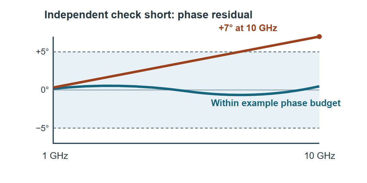
Use the following worksheet after changing a reference plane. Fill in the band, known standard, separate limits for phase and amplitude, and the measured residual for each. Use an independent check short or load for reflection and a characterized verification line or through for transmission, as appropriate. A load can check reflection magnitude and residual match; its small reflection makes it a poor phase reference. A nonzero-length through must be compared against its known delay, not a flat zero-degree trace.

Corrected short phase comparison showing an example in-budget trace and a residual ramp that exceeds the example phase budget
Illustrative phase residual comparison, not measured data. Judge the corrected trace against an independent reference and the applicable budget.
Field Example Decision
Band and test 1–10 GHz; independent short at port 1 DUT plane. Save raw and corrected S11 and the short model.
Phase residual Example limit: ±5°. Example result: +7° at 10 GHz. Hold data. Refit or change method and verify again.
Other checks Enter magnitude error and reconnection spread. Do not accept on phase alone.

If the entire ±5° phase allowance at 10 GHz were assigned to a pure delay error, S21 would permit only 1.39 ps of total delay error; S11 would permit 0.694 ps of one-way error. In a real budget, allocate part of the allowance to the calibration, standard and repeatability as well. The example is not an IPC acceptance limit; use the applicable drawing or agreed measurement procedure.

PCB Test Fixture: Where Port Extension Is Useful

Filter coupon: preserve the filter, remove the feeds

Put the DUT planes at the filter’s port pads when comparing against a pad-referenced model. Determine the one-way delay of both feed sections. Verify with a known through or line before installing the filter. Accept the result only if the reference agrees with phase and loss budgets and the measured filter passband, stopband and group delay meet the project limits. Do not fit the fixture correction on the filter passband and then use the same fit as proof of filter delay.

PCB antenna: report at the feed you intended to tune

If the matching network is specified at its antenna feed, set the port 1 plane there, leaving the antenna and intended matching elements in the measured network. Verify with a separate short or load on a matching coupon, then check the frequency and depth of S11 minima and the usable band against the antenna requirement. A delay-only correction rotates the impedance display but cannot improve return-loss magnitude. If the connector is the specified product test plane, measure and report there instead.

Mismatched connector launch: distinguish the two failure modes

If the launch is itself the product feature under test, leave it inside the DUT boundary and compare to the connector-plane mask. If it is only a fixture and its ripple dominates the error budget, validate a fixture model or calibrate at a closer plane. In both cases retain raw and processed files, calibration identifiers, port directions and the verification result. If there is no check standard or equivalent validation, label the trace as diagnostic instead of releasing it as verified device data.

VNA Port Extension FAQs

Is port extension a replacement for SOLT calibration?

No. Calibrate first at an accessible plane. The extension then moves the reference through a section modeled separately; it does not solve the same systematic error terms as calibration.

Does port extension improve S11?

Delay-only correction changes phase, not magnitude. A reported magnitude change may come from enabled loss compensation or a different processing step, not an improvement of the hardware.

Can port 1 and port 2 use different delays?

Yes. Fit and record each separately. S21 and S12 cross both sections; each reflection uses its own section twice.

Why did my open and short give different delays?

The standards may be nonideal or located at different planes, or fixture mismatch may change the fit. Inspect the geometry and compare the estimates against the phase budget.

Can I use the delay shown by a NanoVNA directly?

Check the software and firmware manual for whether the displayed value or setting represents one-way line delay, round-trip delay or a trace-level phase correction. Verify it on a known length before transferring settings between instruments.

Should I average delay across a wide band?

Only where the fixture behaves as the assumed model and the independent reference meets the required full-band residual. A narrower fitting band does not by itself validate operation outside it.

Does time gating solve the same problem?

No. Gating suppresses selected time events in the processed response. Port extension moves the reporting plane; it does not selectively remove an echo. Keep the unprocessed data either way.

What goes into the Touchstone delivery notes?

Include the original and output planes, port order and reference impedance, sweep band, one-way delay by port, loss and other processing settings, and the verification evidence.

Technical References

Custom RF PCBs With Stackup and Test Coupon Review

Ordering an RF PCB or a separate test coupon? Send EBest Circuit your intended stackup, controlled-impedance targets, launch drawing and test-plane locations before releasing the fabrication data. An early review gives your fabrication and lab teams the same geometry to reference when they compare board and coupon results.

Request an RF PCB quote from EBest Circuit with your Gerbers or ODB++, quantity and required delivery date.

You may also like