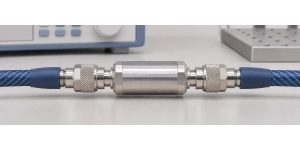
When your VNA test ports cannot mate, do not add a barrel and tell the analyzer it is a zero-length thru. The barrel can introduce loss, delay and mismatch. Use a properly defined thru, a suitable reciprocal Unknown Thru, or the instrument’s adapter-removal workflow. For an Unknown Thru, pass an independent amplitude and phase check before using the setup to judge an RF board.
VNA Calibration: When the Test Ports Cannot Mate
Test ports are non-insertable in this setup if their mating ends cannot directly connect at the intended reference planes. Common examples include two same-sex connectors and two different connector families. The board may fit the two cables perfectly while the cables cannot mate with each other for a flush thru. Do not force the connection or mate connector interfaces that look similar but are not compatible. Confirm the interface, inspect the connectors and use the maker’s specified mating and torque procedure.
Draw the measured board, both mating faces and every adapter you plan to leave in place. The cut between test hardware and the board defines what the data will include. A calibration that verifies well at the wrong cut still describes the wrong network.
SOLR Calibration: What Does an Unknown Thru Solve?
In an Unknown Thru or SOLR calibration, establish the reflection standards at each port, then measure a reciprocal transmission connection in both directions. Rohde & Schwarz uses the name UOSM for a related unknown-through workflow. The instrument constrains the forward and reverse transmission of the thru to be equal as complex quantities (S21 = S12 under consistent references). The thru can still have loss and delay; its two reflections do not have to be identical.
It is the transmission connection that is “unknown,” not the port standards or setup. Follow the calibration wizard and use the appropriate standards at each port. Do not use an isolator, amplifier or other unverified directional device as the assumed reciprocal connection. Equality of magnitude at one frequency is not enough to establish reciprocity.
Adapter Removal Calibration vs. Unknown Thru vs. Defined Thru
Start with the standards you have and the planes the drawing requires. A suitable characterized thru can be the simplest choice; SOLR helps where an accurately defined thru is unavailable. If your platform cannot support SOLR with the required geometry, use a supported adapter-removal workflow or arrange an appropriate calibration kit.
| Method | What you need | Trade-off and check |
|---|---|---|
| Defined thru | A compatible thru and its valid kit definition | Check the actual standard and definition match. Do not substitute an unknown barrel for a flush standard. |
| Unknown thru (SOLR/UOSM) | Suitable reciprocal path, correct port standards, sufficient received signal and supported phase-selection workflow | The analyzer can resolve loss and delay without a full thru model, but verify the phase solution independently. |
| Adapter removal | Compatible standards and supported calibration or characterization steps | The classic two-calibration method needs more reconnections. Control repeatability and confirm the resulting planes. |
Group Delay Measurement: Why the Thru Phase Estimate Matters
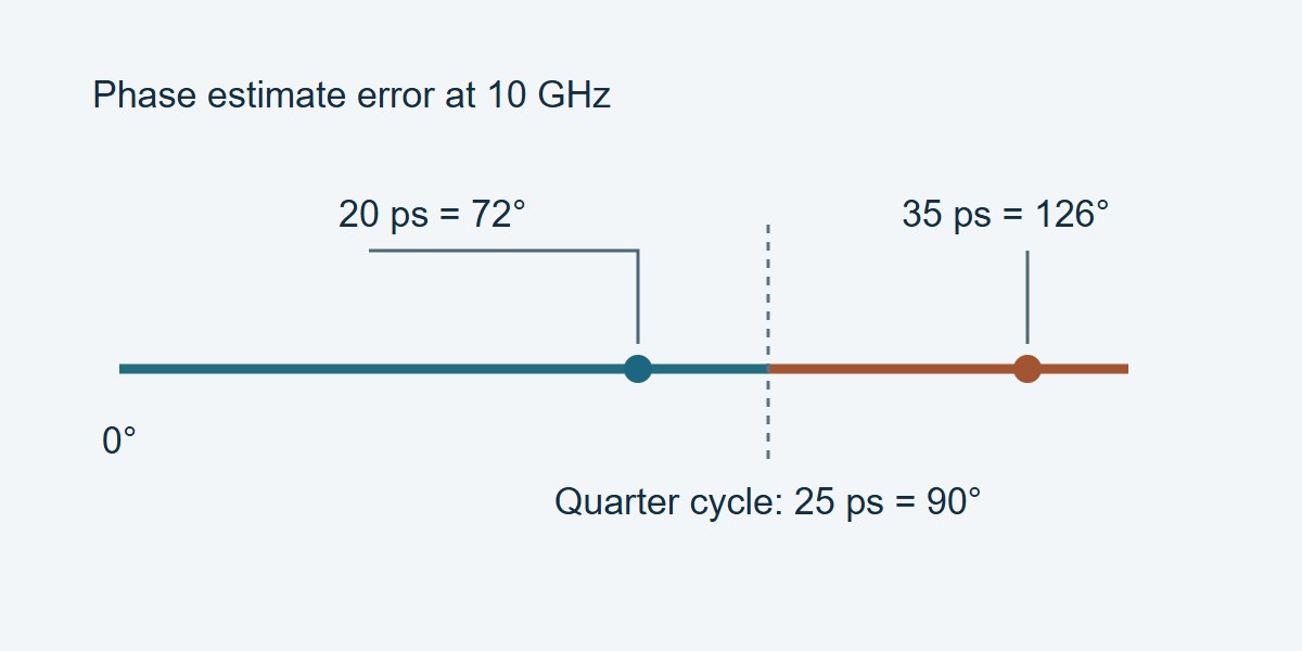
At 10 GHz, a quarter of a period is 25 ps, or 90°. Keysight’s cited M9485A workflow asks for the thru phase estimate to be within a quarter wavelength; refer to the actual instrument’s implementation. The estimate helps choose a phase solution; the two possible transmission solutions can differ by 180° without differing in magnitude. The quarter-cycle example does not mean the thru itself must have less than 25 ps of delay or that errors under 25 ps are acceptable for the final measurement.
In this ideal nondispersive example, an independently established thru delay is 145 ps. A 125 ps guess differs by 20 ps: |Δφ| = 360° × 10 GHz × 20 ps = 72°. A 110 ps guess differs by 35 ps, giving 126°. The latter is outside the quarter-cycle example. For an independently measured and nearly linear unwrapped phase trace, estimate one-way delay as −Δφ ÷ (360° × Δf), with frequency in Hz and phase in degrees. For dispersive media, where phase does not follow one constant delay across the band, follow the analyzer’s phase-selection procedure instead of entering a guessed coax delay.
VNA Reference Plane: Set It Before Connecting the Thru
Set the frequency range, point count, power and any other settings required by the calibration workflow. Keep the cables in their measurement position. Capture the one-port standards at the actual intended mating faces, then connect the reciprocal thru and follow the wizard. Record the thru ID, connection orientation and delay or phase-selection setting. If a transition stays on the measurement cable, account for its location in the calibration design rather than silently moving it after verification.
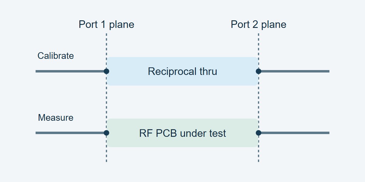
Check transmission through the chosen connection across the whole band. A deep notch near the receiver floor makes the estimate unreliable there. For example, Keysight cautions against 40 dB or more combined loss in the thru and calibration path on the cited workflow; use your instrument and measured signal rather than assuming 40 dB is universal. A plain VNA port extension may correct an accessible path’s delay, but it does not replace a two-port calibration that accounts for adapter mismatch.
Insertion Loss Measurement: Verify Phase, Not Just dB
Measure a separately characterized two-port that was not used to solve the calibration. Use the same frequency grid or a justified reference comparison, correct port order and specified impedance. Check both directions and compare phase as well as magnitude. When the application depends on return loss, verify the reflection response with a suitable independent mismatch standard too. The artifacts and results should cover the ranges that matter to the job. If that check must stay valid across a production run, use this VNA calibration drift guide to set checkpoint intervals and identify boards that need retesting.
| Check | Reference → indication | Decision |
|---|---|---|
| Forward insertion loss | 6.00 dB → 6.09 dB; error +0.09 dB | Passes the example 0.15 dB magnitude-error limit, assuming the agreed uncertainty rule is satisfied. |
| Forward transmission phase | −70° → −62°; difference +8° | Fails the example 5° error limit. Hold calibration and review the settings and reference planes. |
| Reverse transmission and reseat | Independent reverse reference plus readings after a controlled reconnect | Required checks still open. Compare complex results to approved limits; neither earlier row releases the station. |
Where Unknown Thru Helps on an RF PCB Bench
Same-sex ports on a coupon: Select a reciprocal thru that mates to the cables without forcing them into a new position. Qualify the setup in both directions before comparing coupon insertion loss or phase. Keep the board launches in the measurement unless your documented reference planes and separate fixture-removal method say otherwise.
Filter with mixed connector types: Use the correct reflection kit for each connector and a supported thru that mates both ends. Verify return loss and the loss and phase through the passband. Separately demonstrate usable receiver margin if stopband rejection is an acceptance requirement; a passband reference cannot by itself prove the stopband result.
Coax-to-waveguide fixtures: Use appropriate standards and a verified reciprocal transition. If the analyzer requires a dispersive phase selection, follow that process and verify with a distinct known connection over the operating band. Otherwise hold phase-sensitive conclusions.
VNA Calibration Procedure: What to Record Before Release
Record the analyzer and firmware, frequency grid, test settings, port connector types and planes, kit revision, thru ID and orientation, estimated delay or branch selection, and independent verification results. Include units and the governing decision rule. For troubleshooting, first inspect the raw receiver response and repeatable seating; then verify the cal kit and phase choice. Recheck the independent artifact after any change before retesting boards. A corrected plot that looks smooth is not evidence that the calibration passed.
VNA Unknown Thru Calibration FAQs
Does the Unknown Thru need to be lossless?
No. It must meet the instrument’s reciprocity, signal and phase-selection conditions. Its loss must leave enough received signal across the calibration band.
Can the Unknown Thru have different S11 and S22?
Yes. Reciprocity constrains the complex forward and reverse transmission under consistent references, not equality of the two reflection responses.
Can I enter a zero delay for a barrel?
Only when a procedure and verified phase range justify it as an estimate; do not define a real barrel as a perfect flush thru to avoid characterizing it.
Can I use the board itself as the Unknown Thru?
Some analyzers allow it if reciprocity, phase-selection and transmission conditions are met. Avoid using that same board as the only verification artifact.
Why does my loss pass but phase fail?
A magnitude check can miss a wrong phase branch or wrong plane. Check the phase against an independent known connection, then check connection repeatability.
Does a port extension remove adapter mismatch?
Not by itself. A phase or loss model does not recover the adapter’s full reflections and interaction with the device.
What if the two test ports use different connector families?
Use the correct standards for both connector families and a compatible thru or characterized transition within the instrument’s supported workflow.
When should I repeat verification?
Recheck when a cable moves substantially, a connector or adapter changes, a cal setting changes materially, or an independent reference fails. Use the approved interval for ongoing production checks.
Technical References
- Keysight M9485A: Calibration Thru Methods — SOLR, defined thru, adapter removal and setup-specific limits.
- Rohde & Schwarz ZNA User Manual, rev. 39 — UOSM and test-port configuration.
- Rohde & Schwarz ZV-WR technical information, p. 8 — phase selection in the cited dispersive workflow and independent verification.
Custom RF PCBs With Stackup and Coupon Review
Need a custom RF PCB? Share your proposed stackup, layout and connector launches with EBest Circuit for review before fabrication. Include your operating band, impedance targets, coupon needs, quantity and delivery date. Send the files to sales@bestpcbs.com to request a project review and quotation.
You may also like
Tags: vna calibration, VNA Measurement, VNA Port Extension, VNA S21 Measurement