A trimmer potentiometer is a compact adjustable resistor used to fine-tune a circuit after the main component values have been selected. It is commonly found in power supplies, sensor circuits, amplifiers, measurement equipment, and other products that need an occasional manual adjustment for calibration.
This guide explains how a trimmer potentiometer works, how its three pins are used, which types are available, and how to choose a suitable part. It also covers PCB mounting, adjustment access, assembly inspection, and practical calibration so that you can understand the component before adding it to a design or purchasing it for production.
What Is a Trimmer Potentiometer and Where Is It Used?
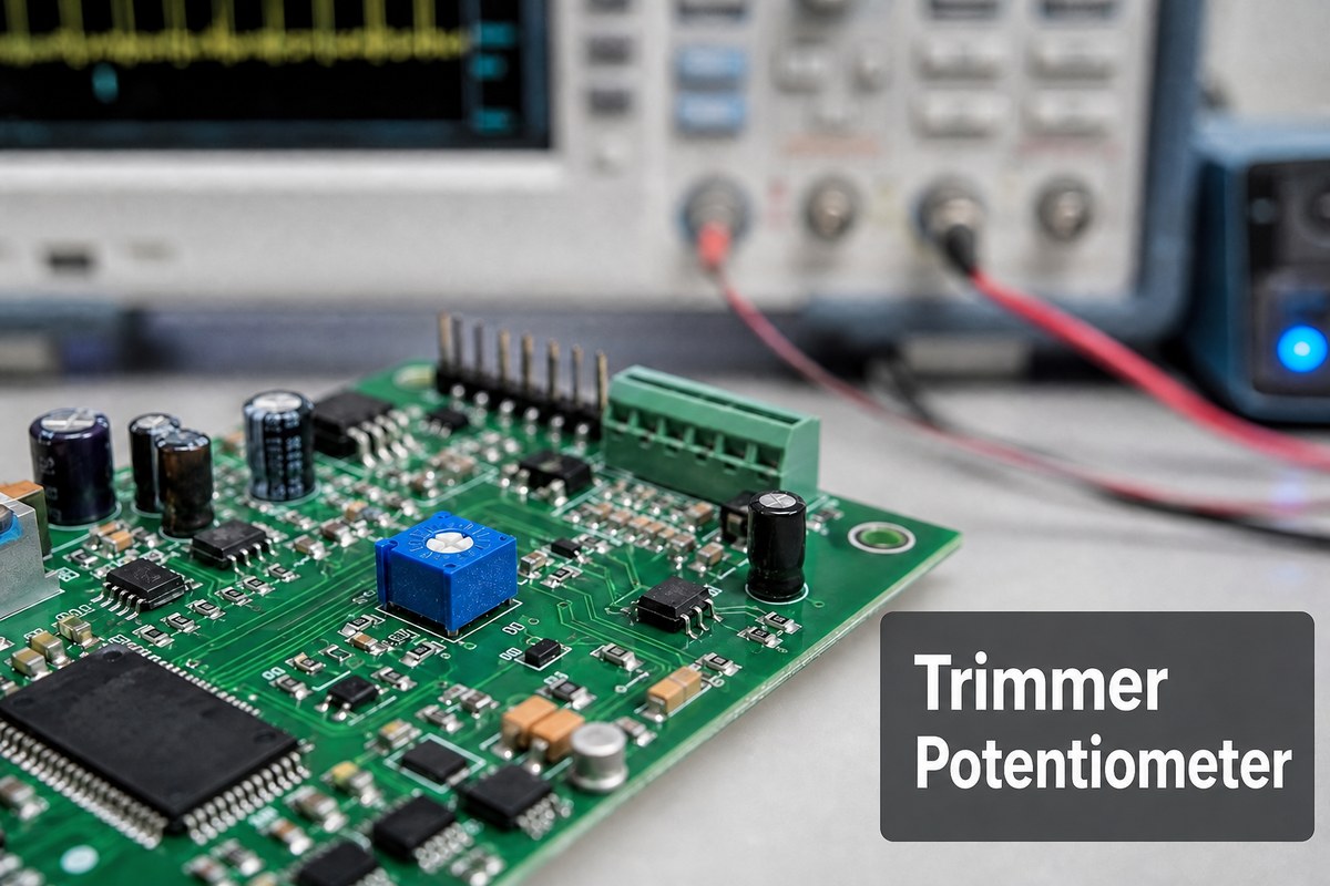
A trimmer potentiometer, also called a trimpot or trim pot, is a miniature variable resistor. Like a standard potentiometer, it contains a resistive track and a movable contact called a wiper. Turning the adjustment screw or rotor moves the wiper along the track and changes the resistance between the wiper and each end terminal.
Most trimmer potentiometers have three terminals:
- Two end terminals connect to the ends of the resistive track.
- The wiper terminal moves electrically between those two ends.
When all three terminals are used, the trimmer normally works as an adjustable voltage divider. When the wiper and one end terminal are used, it works as a variable resistor. The circuit designer chooses the connection according to the function required.
Trimmers are usually adjusted with a small screwdriver or dedicated tool. Unlike a panel-mounted potentiometer, they are not normally intended for continuous user operation. The setting may be adjusted during prototype evaluation, factory calibration, installation, servicing, or periodic maintenance and then left unchanged.
Typical applications include:
- Setting the output voltage of an adjustable power supply.
- Calibrating sensor offset, gain, or threshold.
- Balancing an amplifier or bridge circuit.
- Adjusting display brightness or contrast inside equipment.
- Setting timing, bias, current limit, or reference levels.
- Compensating for normal tolerances in surrounding components.
A trimmer is useful when a circuit needs a small amount of manual correction but does not require software control or an external user knob.
Trimmer Potentiometer vs Potentiometer: Which Fits Your PCB?
A trimmer potentiometer and a standard potentiometer use the same basic principle, but they are designed for different patterns of use.
A trimmer potentiometer is usually better when:
- The adjustment is made only during calibration or servicing.
- The control should remain inside the product.
- PCB space is limited.
- A screwdriver adjustment is acceptable.
- The final setting should not be changed casually by the user.
A standard potentiometer is usually better when:
- The user needs to adjust the setting frequently.
- A shaft, knob, or slider must extend through the enclosure.
- The control is part of the normal product interface.
- Mechanical operating life and user feel are important.
For example, a front-panel volume control is normally a standard potentiometer, while an internal amplifier-bias adjustment is more likely to use a trimmer. A power-supply output that is set once at the factory may use a multiturn trimmer, while a product setting that changes every day needs a user-operated control.
For more detail on the shared three-terminal principle, see this potentiometer wiring guide.
A mechanical trimmer is also different from a digital potentiometer. A digital potentiometer changes its wiper position through an electronic interface and may require firmware, logic-voltage compatibility, and power-up behavior checks. A mechanical trimmer is adjusted directly with a tool and retains its physical position without a control command.
How to Read a Trimmer Potentiometer Pinout Before PCB Layout?
A typical trimmer potentiometer pinout contains two fixed end terminals and one wiper terminal. The resistance between the two end terminals stays close to the rated total resistance. The resistance from the wiper to either end changes as the adjuster turns.
For a three-terminal voltage divider, one end terminal connects to the higher reference, the other connects to the lower reference or ground, and the wiper provides the adjustable output. Reversing the two end terminals normally reverses the direction in which the output changes.
For a two-terminal variable-resistor connection, the circuit uses the wiper and one end terminal. Some designs connect the unused end terminal to the wiper so that a momentary wiper interruption does not leave the circuit completely open. Whether that connection is appropriate depends on the circuit and must be shown in the schematic.
Do not assume that the center physical pin is always the wiper. Different trimmer packages can arrange their terminals differently, and datasheet drawings may use a top, bottom, or terminal-side view. Before creating the PCB footprint, check:
- Which numbered terminal is the wiper.
- Whether the drawing is viewed from the top or bottom.
- Which direction is clockwise adjustment.
- How the terminal numbers map to the schematic symbol.
- Whether the footprint view mirrors the component drawing.
A multimeter provides a simple confirmation. First measure between the two suspected end terminals; the reading should remain nearly constant while the screw turns. Then measure between the suspected wiper and each end. One value should increase while the other decreases.
This quick check is especially valuable when using an unfamiliar package or creating a new CAD library part. It can prevent a footprint that fits mechanically but produces a reversed or non-adjustable circuit.
Which Trimmer Potentiometer Types Fit SMD and Through-Hole Assembly?
Trimmer potentiometers can be classified by mounting method, number of turns, adjustment direction, construction, and resistive material. Understanding these categories makes it easier to narrow a large product list to a part that suits the PCB and the way the circuit will be calibrated.
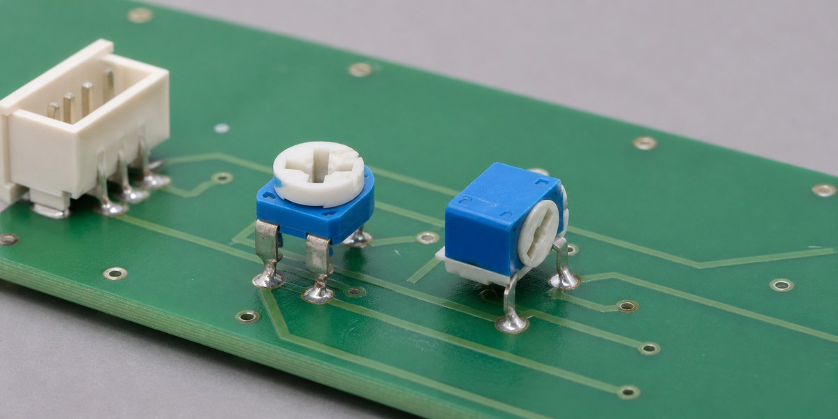
SMD trimmer potentiometers mount directly on PCB pads and are suitable for automated pick-and-place assembly. They save space and are available in very small packages, but the PCB land pattern, reel orientation, component height, and adjustment access must all match the exact part.
Through-hole trimmers use leads inserted through plated holes. They are often larger and may provide stronger mechanical retention or easier manual handling during prototypes and low-volume assembly. They require suitable finished-hole dimensions and a compatible soldering process.
Single-turn trimmers cover their adjustment range in approximately one rotation or less. They are fast to set but can feel sensitive when the acceptable calibration window is narrow.
Multiturn trimmers spread the adjustment across several turns. This gives the operator finer control and can make an exact target easier to reach, although calibration takes longer. The best choice depends on the required precision and production setting time.
Top-adjust trimmers are accessed from above the PCB. Side-adjust trimmers are accessed parallel to the board surface. Bottom-adjust trimmers may require access through the PCB or from the opposite side. This direction often matters as much as the electrical value.
Sealed trimmers offer more protection from flux, dust, and compatible cleaning processes. Open-frame trimmers can be lower in cost but expose more of the resistive mechanism. If the board will be washed, coated, or used in a dusty or humid environment, check the exact manufacturer processing and environmental specifications.
Trimmers may use cermet, carbon, or wirewound resistive elements. Cermet is common in precision board-level applications, carbon can suit cost-sensitive uses, and wirewound construction can offer different power or resistance characteristics. The datasheet, rather than the material name alone, should determine whether a part meets the application.
How to Choose a Trimmer Potentiometer for Resistance and Tolerance?
Start with the resistance range the circuit must cover. The nominal value printed on the trimmer is the total resistance between its two end terminals, not necessarily the resistance that will appear between the wiper and an end terminal after adjustment.
Common values include hundreds of ohms, kilohms, and megohms, but the correct value comes from the circuit. A 10 kΩ trimmer is not automatically interchangeable with a 100 kΩ trimmer simply because both can produce the same output voltage in one unloaded test. The different resistance changes current, loading, noise behavior, and interaction with surrounding components.
The main specifications to compare are:
- Total resistance: the nominal end-to-end resistance.
- Resistance tolerance: the allowed variation in total resistance.
- Power rating: the heat the resistive element can safely dissipate under stated conditions.
- Temperature coefficient: how resistance changes with temperature.
- Adjustment range and number of turns: how finely the setting can be controlled.
- Contact resistance variation: short-term change associated with movement of the wiper.
- End resistance: the residual resistance near the ends of travel.
- Operating temperature: the permitted environmental range.
- Rotational or adjustment life: the number of adjustments the mechanism is designed to withstand.
Resistance tolerance may be less critical than it first appears because the component is adjustable. However, the complete tolerance range must still allow the circuit to reach its target. A wide-tolerance part is unsuitable if some production units cannot cover the required minimum or maximum setting.
Power rating must be checked at the actual operating temperature and wiper position. A rating printed at one temperature may be reduced at higher temperatures. The circuit designer should also check the voltage and current applied to the track rather than treating the trimmer as an ideal adjustment device.
When comparing alternatives, match the electrical specifications and the physical package together. Two trimmers with the same resistance may have different pinouts, turn counts, body heights, adjustment directions, and soldering limits.
Which Trimmer Potentiometer Datasheet Fields Belong in the BOM?
The datasheet explains whether a trimmer is electrically and mechanically suitable. The BOM ensures that purchasing orders the exact version selected by the designer. Both should identify more than a generic description such as “10K trim pot.”
Key datasheet fields include:
- Complete series and manufacturer part number.
- Total resistance and resistance code.
- Resistance tolerance and power rating.
- Number of turns and adjustment direction.
- SMD or through-hole mounting style.
- Top-, side-, or bottom-adjust configuration.
- Terminal numbering and circuit diagram.
- Body dimensions, terminal pitch, and PCB layout.
- Packaging type, such as tape-and-reel, tube, or bulk.
- Operating temperature and environmental sealing.
- Recommended soldering and cleaning conditions.
The BOM should carry the full orderable manufacturer part number, quantity, and reference designators. Suffixes may identify resistance value, lead-free termination, packaging, adjustment style, or other options. Omitting a suffix can result in a part that belongs to the same family but does not fit the intended assembly process.
If alternative parts are permitted, list them separately rather than replacing the approved part with a generic purchasing note. Compare each alternate for:
- Pin-to-pin electrical compatibility.
- PCB footprint and body-height compatibility.
- Adjustment direction and tool access.
- Number of turns and calibration behavior.
- Power, temperature, and environmental ratings.
- Packaging and soldering-process compatibility.
The purpose is not to make the BOM longer. It is to prevent a visually similar trimmer from changing how the circuit is assembled or adjusted.
How Do Trimmer Potentiometer Knob Access and PCB Clearance Affect Assembly?
Electrical selection alone does not guarantee that a trimmer will be usable. The adjustment screw, rotor, or small knob must remain accessible after nearby components, cables, heat sinks, shields, and the enclosure are installed.
Top-adjust and side-adjust parts create different layout needs. A top-adjust trimmer needs vertical tool clearance. A side-adjust trimmer needs an open path parallel to the PCB. If the tool enters through an enclosure opening, the trimmer must align with that opening across normal PCB, enclosure, and assembly tolerances.
Check the following clearances in the final assembled state:
- Space for the screwdriver or adjustment tool.
- Safe distance from energized or high-voltage conductors.
- Clearance from tall capacitors, connectors, and cable assemblies.
- Clearance from heat sinks and other hot components.
- Maximum component height below the enclosure.
- Space for the operator or calibration fixture to approach the adjuster.
Also consider what happens after calibration. Conformal coating, adhesive, staking material, or potting compound can block the mechanism. If the trimmer must remain adjustable, the assembly drawing should identify a keepout or masking requirement. If it is adjusted once and then locked, the approved locking material and application point should not damage the mechanism.
Silkscreen can help by showing the reference designator and, when useful, the direction that increases the controlled value. However, the direction should be confirmed by circuit behavior because reversing the two end terminals reverses the electrical response.
The potentiometer PCB layout guide provides more information about placement and routing. For mechanical access, a simple 3D model or enclosure overlay often reveals problems that are not obvious in a two-dimensional PCB view.
How Can PCBA Inspection Catch Trimmer Potentiometer Placement and Soldering Errors?
PCBA inspection should confirm that the installed trimmer matches the BOM, sits correctly on the PCB, and remains adjustable. The most common problems are usually easy to understand once the package and pinout are known.
Common placement and assembly errors include:
- Installing a part with the correct resistance but the wrong adjustment direction.
- Rotating an asymmetric SMD package.
- Using a mirrored or incorrect footprint.
- Fitting a substitute whose body interferes with nearby components.
- Blocking the adjustment screw with a connector, cable, or coating.
- Leaving an open-frame mechanism contaminated with flux or debris.
- Creating weak, bridged, or insufficient solder joints.
For an SMD trimmer, AOI may confirm presence, alignment, orientation features, and visible solder joints. Very small terminals or joints under the body may require a process-specific inspection method. Through-hole trimmers should be checked for correct seating, lead protrusion, solder wetting, and mechanical stability.
Electrical checks add information that visual inspection cannot provide. Measuring between the two end terminals can confirm the expected total resistance. Measuring from the wiper while turning the adjustment can confirm that the mechanism changes smoothly. A powered functional test is still needed to prove that the circuit output moves in the correct direction and reaches the intended range.
If a trimmer appears damaged after soldering, check the component’s approved temperature profile and cleaning limits. Excessive heat, unsuitable cleaning, or mechanical force from the adjustment tool can affect the housing or internal contact.
EBest Circuit (Best Technology) can support component sourcing, SMD and through-hole assembly, and inspection through its circuit board assembly services. The useful customer requirement is a clear part number and a measurable output range, not a long internal inspection procedure.
How to Use a Trim Pot in Functional Test and Calibration?
Before powering the circuit, check the trimmer datasheet, pinout, and starting position. Some circuits can produce an unsafe output if the wiper begins near one end of travel. When the design is sensitive to the initial setting, the test instruction should specify a preset resistance or a safe startup method.
A practical adjustment sequence is:
- Use the correct insulated or manufacturer-recommended adjustment tool.
- Connect the power supply, load, signal source, and measuring instrument required by the circuit.
- Power the board under the specified test conditions.
- Measure the controlled voltage, current, frequency, gain, or threshold.
- Turn the trimmer slowly while watching the measurement.
- Stop when the reading enters the target range.
- Allow the circuit to stabilize and check the value again.
- Record or mark the setting when traceability is required.
If the reading moves in the wrong direction, first check the end-terminal connections and the test instruction. If the reading does not change, check whether the wiper is connected, whether the footprint matches the pinout, and whether the trimmer has reached an end stop.
Do not force the screw after the mechanism reaches the end of travel. If the target cannot be reached within the normal range, the problem may be the wrong resistance value, an incorrect surrounding component, excessive circuit tolerance, a wiring error, or a damaged trimmer.
Multiturn trimmers are useful when the final value is sensitive to small movement. Single-turn parts are faster when the acceptable range is broad. The correct choice makes calibration both repeatable and practical rather than merely possible.
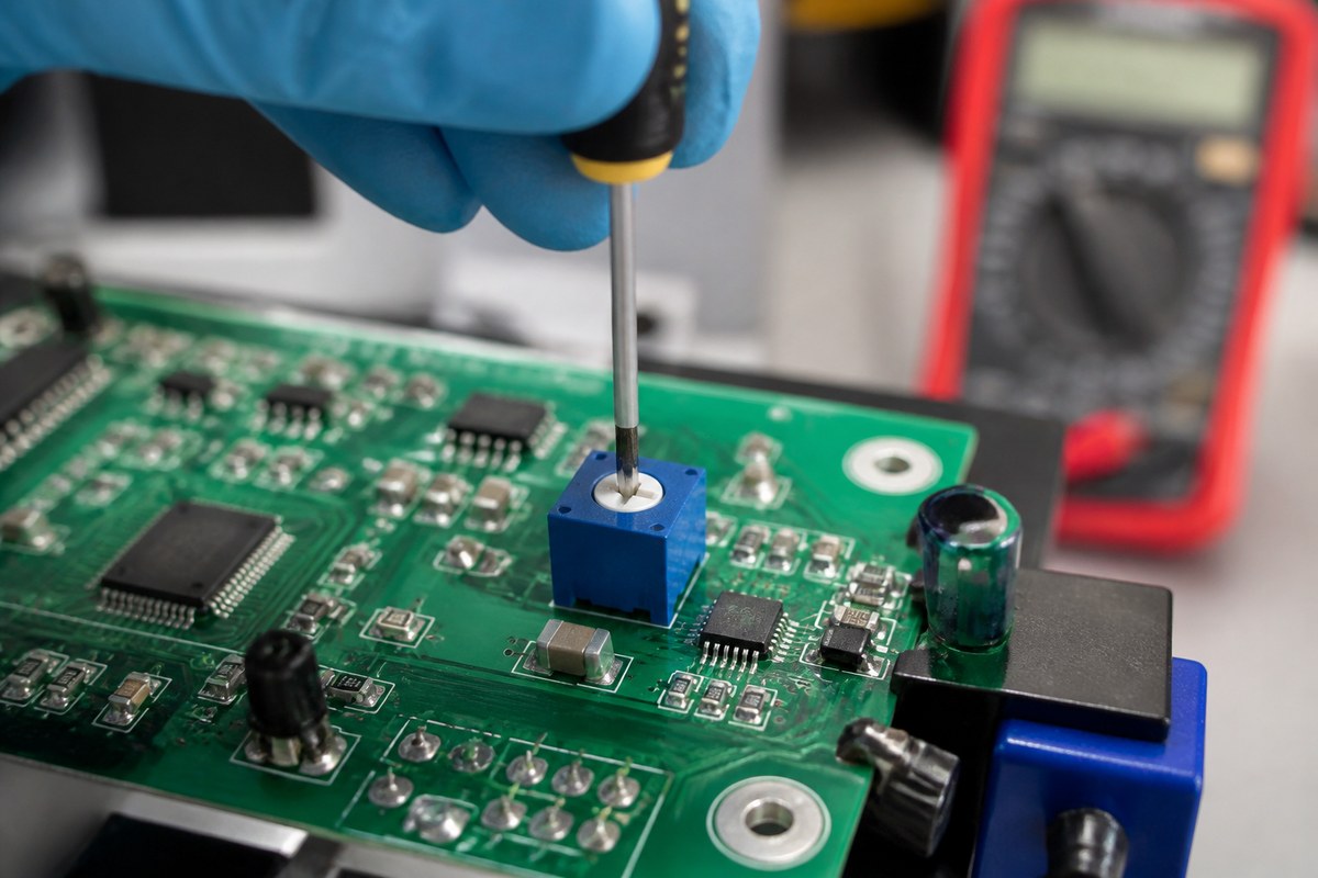
Engineering Example: Verifying a Board-Mounted Trimmer Potentiometer Before PCBA Assembly
A low-volume LED tester project handled by EBest Circuit used a display connector close to a board-mounted trimmer potentiometer. Before assembling the five-board pilot lot, our engineering team needed to confirm that the trimmer would fit the PCB and remain accessible after assembly.
A BOM entry such as “10 kΩ trimmer” was not specific enough. Parts with the same resistance may have different pinouts, body sizes, and adjustment directions. A side-adjust trimmer, for example, could fit the PCB footprint but become blocked by the nearby display connector.
EBest Circuit compared the trimmer potentiometer datasheet with the PCB design and checked:
- Pinout and lead spacing.
- Body position and seated height.
- Adjustment direction.
- Connector clearance.
- Screwdriver access.
- Soldering compatibility.
The confirmed part number, orientation, and adjustment keepout could then be added to the assembly drawing. During functional testing, each board could be adjusted while the specified output was monitored.
This verification helped prevent footprint mismatches and inaccessible adjustment points before PCBA assembly. It also confirmed that the trimmer potentiometer would work as both an electrical component and an accessible calibration control.
FAQs About Trimmer Potentiometers
What does a trimmer potentiometer do?
It provides a small manual adjustment for resistance, voltage division, calibration, or threshold setting. The exact function depends on how the three terminals are connected in the circuit.
What is the difference between a trimmer potentiometer and a variable resistor?
A trimmer potentiometer is a physical component with three terminals. It can operate as a voltage divider using all three terminals or as a variable resistor using the wiper and one end terminal.
Which pin is the wiper on a trimmer potentiometer?
The wiper is often shown as terminal 2, but physical arrangements vary. Always confirm the exact datasheet drawing instead of assuming that the center physical pin is the wiper.
Is a multiturn trimmer better than a single-turn trimmer?
Not always. A multiturn trimmer provides finer adjustment but takes longer to set. A single-turn trimmer is faster but may be more sensitive. The better choice depends on the calibration tolerance and process.
Can a trimmer potentiometer be adjusted after conformal coating?
Only if the adjuster remains accessible and the coating process is compatible with the component. Specify a coating keepout or temporary mask when post-coating adjustment is required.
A suitable trimmer potentiometer should provide the required electrical range, fit the PCB footprint, remain accessible, and allow the circuit to be calibrated without excessive sensitivity. Check the exact datasheet, pinout, mounting style, adjustment direction, and operating limits before finalizing the part.
For PCB fabrication, component sourcing, PCBA, inspection, or customer-defined test support, send your files and requirements to EBest Circuit (Best Technology) at sales@bestpcbs.com.