To compare a 50 Ω VNA file with a 75 Ω specification, renormalize the complex S-parameters to the required impedance at the same reference planes. Do not change only the Touchstone header. Renormalization changes how the same electrical network is described. It does not change the actual VNA ports, remove a launch, or repair a poor measurement.
This guide uses linear networks and positive real reference resistances. For complex reference impedances or mixed-mode ports, use a documented method that handles the applicable wave definitions and port mapping.
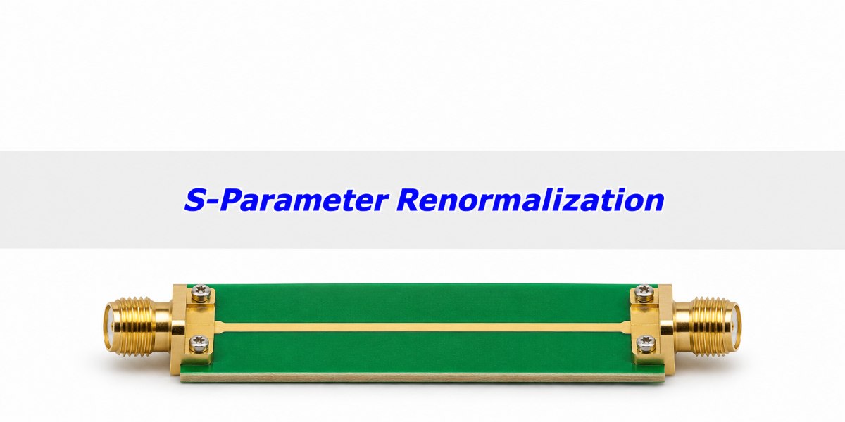
What Is S-Parameter Renormalization?
S-parameter renormalization expresses the same network at the same physical ports using a different impedance basis for the incident and reflected waves. The voltage-current relationships of the network stay the same; the S-parameter values need not. This is why the same measured circuit can have different return loss under two standards that specify different reference impedances.
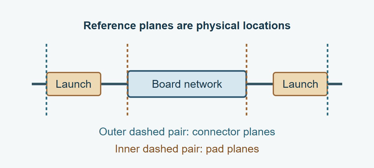
Start by recording the original impedance at each port, the port order, the reference plane and the target specification. If the specification calls for a 75 Ω connector-to-connector measurement, a 75 Ω result at the pads is not automatically comparable. Agree on the plane first, not only the impedance number.
Reference Impedance vs. the Physical Termination
The reference impedance is part of the wave definition; a termination is a physical component or a load in a simulation. Changing the reference of a recorded file does not replace the coaxial hardware or change how the source drove the original measurement. If you connect an external load in a simulator, set that load explicitly even when the file is already in the desired reporting basis.
In a two-port S11 reading, the other port is matched to its reference for that S-parameter definition. When you renormalize both ports, that matched condition is different. That is one reason a one-port conversion on S11 alone does not generally reproduce the correct two-port result.
Reflection Coefficient Formula: Check a Known Load First
A known ideal 75 Ω load produces a reflection coefficient of +0.20 in a 50 Ω reference system and zero in a 75 Ω reference system. For a positive real reference resistance R and a load impedance Z, Γ = (Z − R)/(Z + R). The magnitude in dB is 20 log10|Γ|; the positive return-loss convention takes the opposite sign.
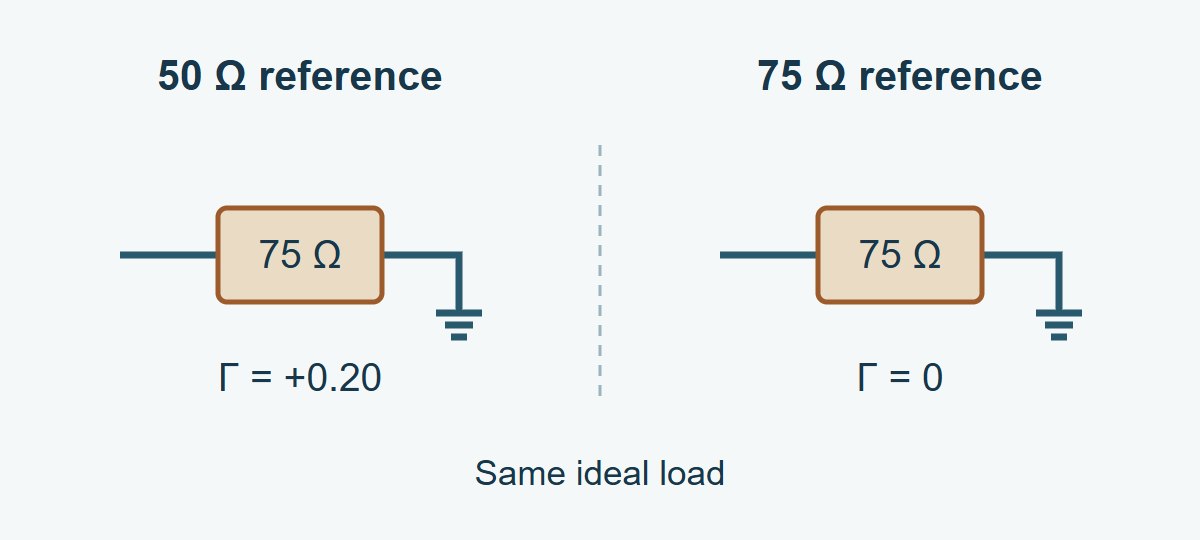
The +0.20 result is −13.98 dB in S11 magnitude, or 13.98 dB return loss. From the original complex Γ, recover the load as Z = R(1 + Γ)/(1 − Γ), then apply the new reference to that same Z. Do not do this from magnitude alone: positive and negative reflections of the same magnitude do not give the same impedance. An ideal open, Γ = +1, makes the finite-Z form singular; use a supported conversion or its limit. A real measured 75 Ω standard will not read exactly zero after conversion.
S21 Measurement: Recalculate the Whole Two-Port
Use a full-matrix renormalization in a tool that supports the file’s wave definition and new per-port values. Do not change only S11 or S22 and leave transmission terms untouched. The result at one port depends on what happens at the other, and complex phase information is part of the data.
Take an ideal 25 Ω series resistor as a check, with the same reference resistance R at both ports. The series current and voltage drop give S11 = 25/(2R + 25) and S21 = 2R/(2R + 25). At 50 Ω, S11 = 0.20 and S21 = 0.80 (−1.94 dB). At 75 Ω, S11 = 1/7 and S21 = 6/7 (−1.34 dB). The reported transmission changed by about 0.60 dB; the resistor did not change. This is an ideal lumped example, not a prediction for a frequency-dependent PCB launch or an uneven pair of port references.
50 Ohm vs. 75 Ohm: Choose the Right Kind of Change
Change the reporting basis only if that is what the problem requires. If the data include a fixture that is not part of the specification, solve the reference-plane problem separately. If the measurement itself cannot resolve the device, improve or verify the physical setup.
| What needs to change? | Operation | What to verify |
| Wave reference, with the same physical planes | Renormalize the full complex network. | Correct original and new references; known-load or known-network check. |
| Location of the reference planes | Use a qualified calibration at the new planes or remove a characterized fixture. | Which launches remain, and whether the fixture model is valid in band. |
| Hardware mismatch or usable range | Adapt and calibrate the measurement setup as appropriate. | Hardware compatibility, matching, repeatability and residual noise. |
VNA Port Extension vs. a Reference Impedance Change
Port extension typically compensates for electrical delay and may include loss correction on some instruments. It is not a generic correction for fixture mismatch, and changing R does not move a calibration plane. Verify the instrument’s implementation. If the fixture has appreciable discontinuities or coupling, use an appropriate fixture characterization instead of treating it as a uniform delay.
VNA Calibration: Check What the Physical Setup Can Prove
Keep the instrument’s physical ports and its software impedance setting separate. For example, Keysight’s E5080A system-impedance guidance distinguishes its nominally 50 Ω physical ports from a mathematical 75 Ω display reference. It gives a 75 Ω measurement workflow using suitable matching pads and 75 Ω calibration standards. Apply the supported method for your actual analyzer, calibration kit and rated adapters.
If you have a suitable 50 Ω linear measurement, you can convert it mathematically, but conversion does not restore a response missing below the floor or remove unstable coupling. When weak S21 limits the claim, use the VNA IF bandwidth guide to verify receiver noise and fixture leakage before converting or releasing the result.
Touchstone File: Check the Export Before Sending It
Save the original raw file, export a separate converted copy, and reopen it in the receiver’s tool. In Touchstone 2.0 and 2.1, the optional [Reference] keyword supplies port-ordered real reference resistances and overrides the option-line default when present. Touchstone 1.0 uses a single shared reference on the option line; 1.1 has its own per-port syntax. Check importer support rather than relying on the file extension alone.
For a passive PCB channel, use the full-matrix S-parameter passivity check on both versions. Exporting the expected reference values and matching a single transmission trace does not prove the converted data is safe to use in a passive channel model.
| Record to check | Example entry | Pass condition |
| Physical planes and port order | Connector planes; P1 input, P2 output | Both versions have the same plane and mapping unless a separate change is documented. |
| Original and export reference | 50/50 Ω → 75/75 Ω | Reopened file reports the intended values and transformed complex data. |
| Known-network check | Ideal series 25 Ω: S21 ≈ 0.857 at 75 Ω | Use the complex value and expected tolerance, not just the marker after rounding. |
| Round-trip check | Convert the reopened copy back to 50/50 Ω | Original complex data are recovered within declared numerical tolerance; this tests software and data handling only. |
Use this table for a vendor data handoff. For example, if the exported resistor check still shows S21 = 0.80 while the file shows 75/75 Ω, do not release it: verify that the complex matrix was changed and that the reader recognized the reference format. For a coaxial filter, compare the required return loss and transmission in the specified band at the defined planes. For simulation correlation, verify using the same file reference, frequency grid and actual load definitions. If a change in reference moves the margin around a limit, verify again rather than calling it a physical redesign benefit.
S-Parameter Renormalization FAQs
Can I edit only R 50 to R 75?
No. That changes the metadata without computing the new wave values. Use a valid full-complex conversion and keep the original file.
Can I convert a screenshot that shows S11 in dB?
Not uniquely. You generally need the complex data or both magnitude and phase. Ask for the original file or remeasure.
Does selecting 75 Ω make VNA hardware 75 Ω?
No. A software setting cannot change the physical port construction. Use the instrument’s supported hardware and calibration method when the physical measurement needs to be adapted.
Can ports have different reference resistances?
Yes, when the format and tool support them. Enter the values in the correct port order and verify what the importing program actually applies.
Should I use a different number on the Smith chart after conversion?
Use the chart reference that matches the data and task. A shifted point with a new reference is not evidence that the measured load physically changed.
Does a round trip prove accuracy?
No. It checks conversion and data handling. A measurement can round-trip faithfully and still carry calibration error, noise or fixture leakage.
Can I remove an SMA launch by changing references?
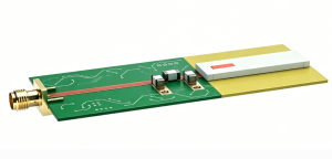
No. Identify the intended plane and use suitable calibration or characterized de-embedding for the launch, independently of the impedance basis.
Do these examples apply to mixed-mode or complex reference data?
Not directly. Define modes, port order and the scattering-wave convention, then use an appropriate documented transformation. This guide uses positive real single-ended references.
Technical References
- Keysight E5080A: System Impedance, mathematical reference and physical 75 Ω setup example.
- IBIS Open Forum: Touchstone 2.1 specification, option line and [Reference] rules.
- scikit-rf: Renormalizing S-parameters, reference transformation and wave-definition caveats.
- Keysight: Reference Plane Adjustment, distinction between port extension and fixture de-embedding.
Custom RF PCBs With Stackup and Test Coupon Review
Send EBest Circuit your stackup, RF connector footprints and test band before release. Reviewing the trace geometry and test coupon together lets your team state which line construction the fabrication check covers and which launches or device responses need separate validation.
Request an RF PCB fabrication quote at sales@bestpcbs.com. Include your released fabrication files, quantity, target impedance by structure, and the required reference planes and reporting conditions.