A surface mount resistor is a compact resistor mounted directly onto PCB pads and assembled using surface mount technology. Common packages range from tiny 01005 and 0201 parts to larger 1206, 2010, and 2512 resistors used where more power or board space is available.
Selecting the right part involves more than resistance value. Engineers also need to consider resistor type, package size, tolerance, power rating, working voltage, TCR, and markings. This guide explains the most common surface mount resistor sizes, types, codes, and values, then shows how to choose one for a PCB.
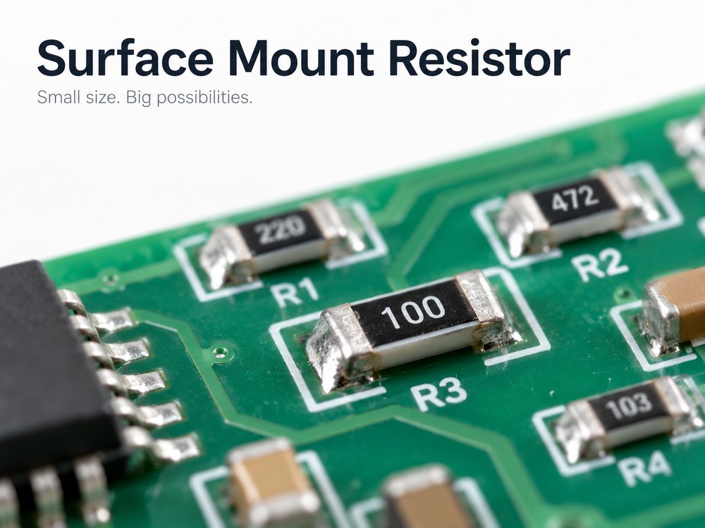
What Is a Surface Mount Resistor?
A surface mount resistor is a resistor designed to sit directly on conductive pads on the surface of a PCB. It does not use long leads passing through drilled holes like a through-hole resistor.
Other names commonly used for the same component include:
- SMD resistor
- chip resistor
- surface mount chip resistor
- SMT resistor
SMD means surface-mount device, while SMT refers to the process used to assemble surface-mount components.
A typical chip resistor contains:
- a ceramic substrate
- a resistive layer
- metal terminal electrodes
- a protective coating
During PCB assembly, solder paste is printed on the pads, the resistor is placed by pick-and-place equipment, and the joint is formed during reflow soldering.
The surface mount resistor symbol on a schematic is normally the same standard resistor symbol used for a through-hole part. Its reference designator is usually R, such as R1 or R24. Package information such as 0603 or 0805 is defined in the PCB footprint rather than the schematic symbol.
What Are the Main Surface Mount Resistor Types?
The main surface mount resistor types differ in resistive material, precision, temperature stability, current capability, and cost.
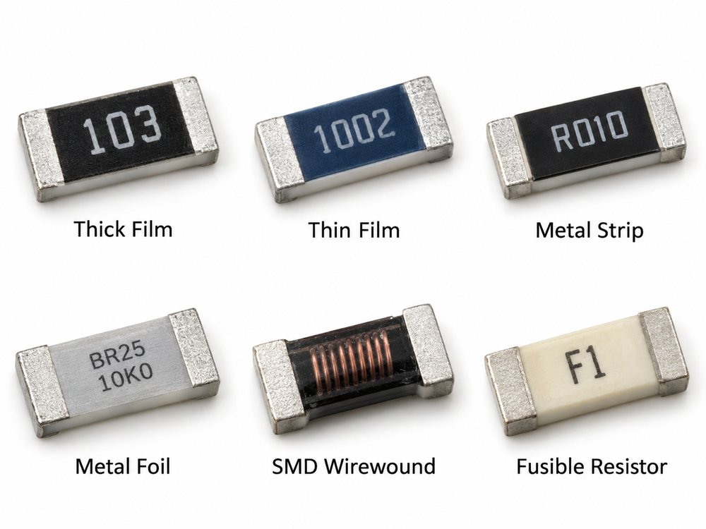
| Type | Main Characteristic | Common Use |
| Thick film | Cost-effective and widely available | General PCB circuits |
| Thin film | High precision and low TCR | Analog and measurement circuits |
| Metal strip | Very low resistance | Current sensing |
| Metal foil | High stability and accuracy | Precision electronics |
| SMD wirewound | Higher power and pulse capability | Power circuits |
| Fusible | Designed to open under overload | Circuit protection |
Thick-film resistors
These are the standard choice for many PCB designs. They cover a broad resistance range and are readily available in packages such as 0402, 0603, 0805, and 1206.
Typical uses include:
- pull-up and pull-down networks
- LED current limiting
- bias circuits
- general signal conditioning
Thin-film resistors
Thin-film parts are used when tighter tolerance and lower temperature coefficient are required. They are common in:
- precision amplifiers
- sensor interfaces
- measurement circuits
- accurate voltage dividers
Metal strip resistors
Metal strip parts are mainly used for low-resistance current sensing. Values may be measured in milliohms rather than ohms, making them useful in battery systems, power supplies, motor drives, and power converters.
The resistor type should therefore match the electrical requirement. Two resistors with the same resistance and package size can have very different tolerance, TCR, pulse capability, and stability.
What Surface Mount Resistor Sizes Are Common?
Common surface mount resistor sizes include 0201, 0402, 0603, 0805, 1206, 2010, and 2512. Smaller packages reduce PCB area, while larger packages generally offer higher power capability and easier handling.
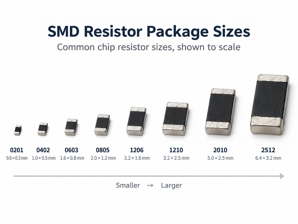
| Imperial Size | Metric Code | Approx. Size (mm) | Typical Conventional Power* |
| 01005 | 0402 | 0.4 × 0.2 | ~0.03 W |
| 0201 | 0603 | 0.6 × 0.3 | ~0.05 W |
| 0402 | 1005 | 1.0 × 0.5 | ~0.063 W |
| 0603 | 1608 | 1.6 × 0.8 | ~0.10 W |
| 0805 | 2012 | 2.0 × 1.25 | ~0.125 W |
| 1206 | 3216 | 3.2 × 1.6 | ~0.25 W |
| 1210 | 3225 | 3.2 × 2.5 | ~0.5 W |
| 2010 | 5025 | 5.0 × 2.5 | ~0.75 W |
| 2512 | 6332 | 6.3 × 3.2 | ~1 W |
*These are common reference ratings rather than universal specifications. The exact rating must be checked in the resistor manufacturer’s datasheet.
The imperial package code approximately represents component length and width in hundredths of an inch. For example:
- 0603 ≈ 0.06 × 0.03 inch
- 0805 ≈ 0.08 × 0.05 inch
- 1206 ≈ 0.12 × 0.06 inch
Metric and imperial codes should not be confused. An imperial 0603 package, for example, corresponds to metric 1608 rather than metric 0603.
Package size also affects manufacturability. Moving from 0805 or 0603 to 0402, 0201, or smaller parts generally requires tighter control of:
- PCB pad dimensions
- solder paste volume
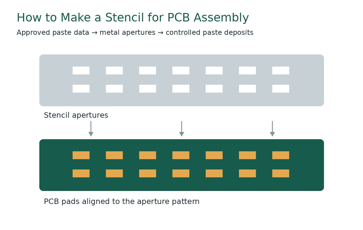
- stencil apertures
- placement accuracy
- component spacing
- automated optical inspection
- rework
The smallest surface mount resistor is therefore not automatically the best choice. Use a smaller package when PCB density requires it, not simply because the package is available.
How Do You Read Surface Mount Resistor Codes and Markings?
Surface mount resistor markings use numbers and letters to represent resistance because the component body is too small for traditional color bands. The most common surface mount resistor code systems are 3-digit codes, 4-digit codes, R notation, and EIA-96.
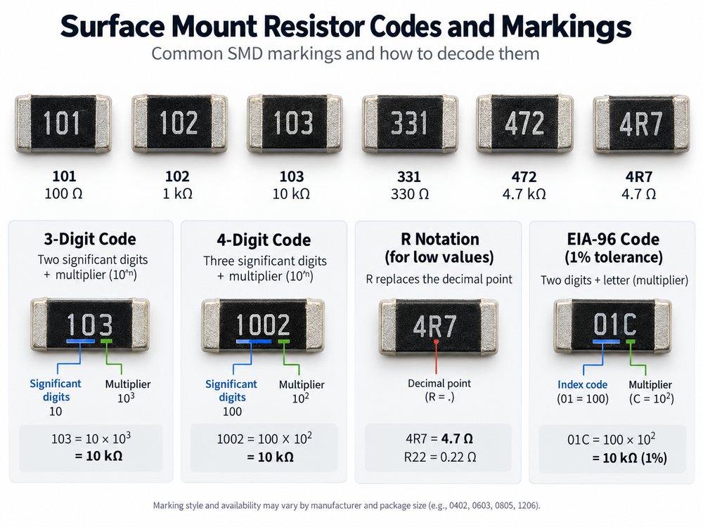
3-digit surface mount resistor code
The first two digits are significant figures. The third digit tells you how many zeros to add.
| Code | Calculation | Value |
| 101 | 10 × 101 | 100 Ω |
| 102 | 10 × 102 | 1 kΩ |
| 103 | 10 × 103 | 10 kΩ |
| 331 | 33 × 101 | 330 Ω |
| 472 | 47 × 102 | 4.7 kΩ |
4-digit surface mount resistor code
The first three digits are significant figures and the fourth digit is the multiplier.
Examples:
1001= 100 × 101 = 1 kΩ4701= 470 × 101 = 4.7 kΩ1002= 100 × 102 = 10 kΩ4702= 470 × 102 = 47 kΩ
Four-digit markings are often found on tighter-tolerance resistor series.
R notation
For low resistance values, R is used as the decimal point.
Examples:
R10= 0.10 ΩR47= 0.47 Ω2R2= 2.2 Ω4R7= 4.7 Ω
EIA-96 resistor markings
EIA-96 uses two digits followed by a letter. The two-digit number refers to one of 96 standard base values, while the letter gives the multiplier.
Because the number is a lookup code rather than the resistance itself, an EIA-96 surface mount resistor code chart or calculator is usually the quickest way to decode it.
Unmarked surface mount resistors
01005, 0201, and some other small resistors may have no readable top marking. Their value should be identified using:
- BOM data
- manufacturer part number
- reel label
- assembly records
- resistance measurement
Appearance alone is not enough because different values can use identical packages.
Surface Mount Resistor Values: What Do 100, 101, 102 and 103 Mean?
For a standard 3-digit surface mount resistor marking, the first two digits give the significant value and the third digit gives the multiplier.
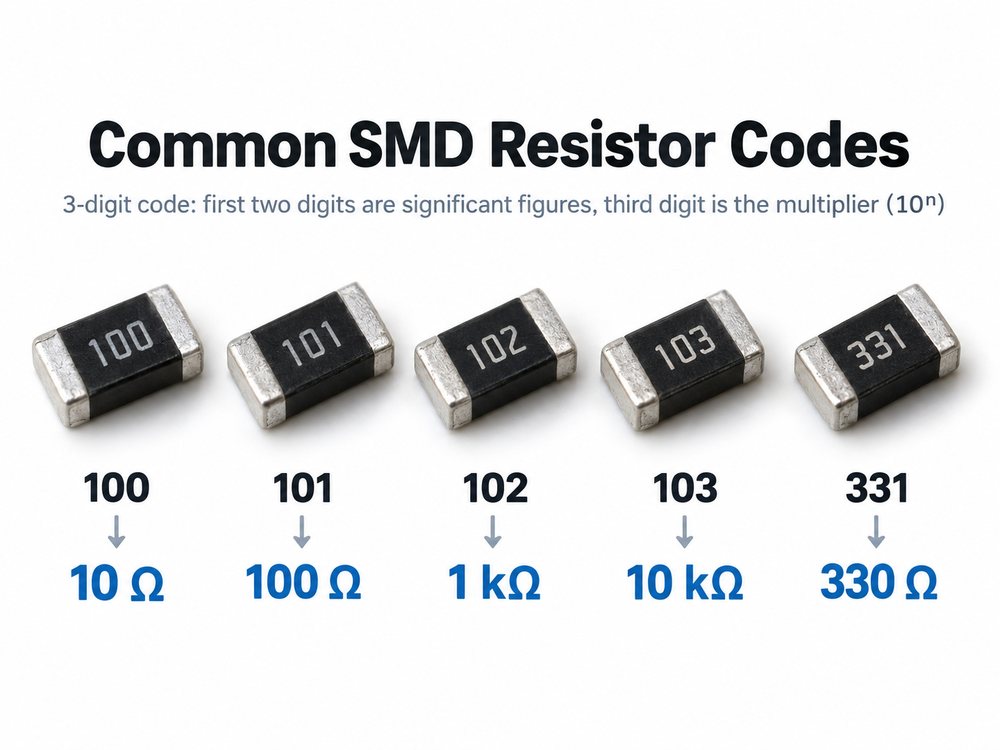
| Surface Mount Resistor Code | Resistance Value |
| 100 | 10 Ω |
| 101 | 100 Ω |
| 102 | 1 kΩ |
| 103 | 10 kΩ |
| 221 | 220 Ω |
| 331 | 330 Ω |
| 472 | 4.7 kΩ |
| 104 | 100 kΩ |
The code 100 is particularly easy to misread.
100 means:
10 × 100 = 10 Ω
It does not normally mean 100 Ω.
A 100 ohm surface mount resistor commonly uses the code 101:
10 × 101 = 100 Ω
Other common examples are:
102surface mount resistor = 1 kΩ103surface mount resistor = 10 kΩ331surface mount resistor = 330 Ω472surface mount resistor = 4.7 kΩ
For example, a standard 330 ohm 0805 surface mount resistor may carry the marking 331 when that resistor series uses body markings.
How Do You Choose the Right Surface Mount Resistor for a PCB?
Choose a surface mount resistor by checking the required resistance first, then tolerance, power, voltage, temperature behavior, pulse load, and package size.
The main specifications are:
- Resistance: Match the nominal value required by the circuit.
- Tolerance: ±5% and ±1% are common; precision designs may need ±0.5%, ±0.1%, or tighter.
- Power rating: Calculate actual dissipation and leave suitable operating margin.
- Working voltage: Check this separately from wattage, especially in high-voltage circuits.
- TCR: Use a lower temperature coefficient when resistance stability over temperature matters.
- Pulse rating: Check surge capability for startup, switching, discharge, and transient loads.
- Package: Select a size that meets both electrical and PCB space requirements.
- Availability: Check whether the exact series is practical to source throughout production.
Resistor power can be estimated using:
P = I2R
P = V2 / R
Package wattage should not be treated as a universal limit. The usable power also depends on the exact resistor series, ambient temperature, PCB copper area, and manufacturer derating curve.
Package selection also affects assembly. An electrically suitable 0201 resistor may be unnecessary if an 0603 fits comfortably and the product does not require extreme component density.
For production PCBs, the preferred package is usually the smallest size that meets the electrical and layout requirements without adding unnecessary assembly difficulty.
Surface Mount Resistor vs Through-Hole Resistor: Which Should You Use?
The surface mount resistor vs through hole choice depends on assembly method, PCB area, mechanical needs, and power requirements. A surface mount resistor is usually preferred for compact and automated PCB assembly, while a through-hole resistor remains useful when easy manual handling, mechanical retention, or certain high-power requirements matter more.
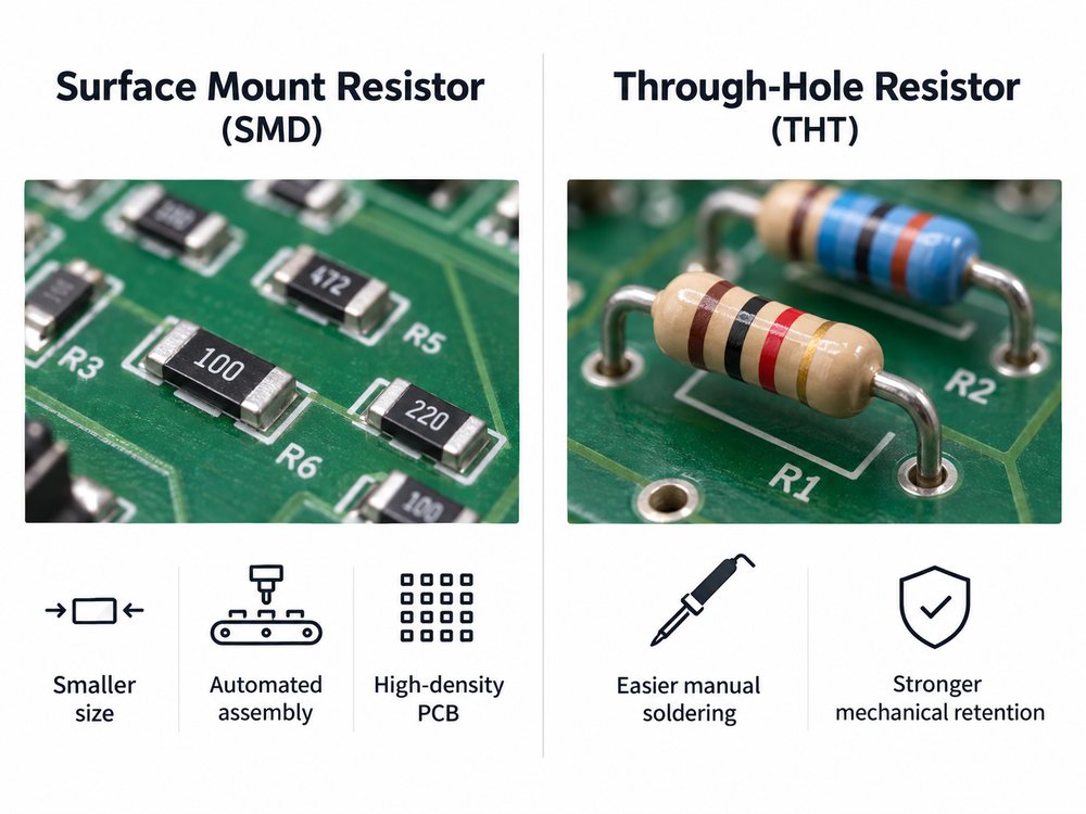
| Factor | Surface Mount Resistor | Through-Hole Resistor |
| PCB area | Smaller | Larger |
| Automated assembly | Well suited | Less efficient |
| Component density | Higher | Lower |
| Lead inductance | Lower | Higher |
| Manual soldering | More difficult | Easier |
| Mechanical retention | Lower | Stronger |
| Rework | Harder at small sizes | Usually easier |
| High-density PCB | Preferred | Less suitable |
Choose a surface mount resistor when the design prioritizes:
- compact PCB size
- automated SMT production
- high component density
- short electrical paths
- double-sided component placement
Choose a through-hole resistor when the design benefits more from:
- manual assembly
- straightforward repair
- stronger mechanical retention
- large leaded power components
- simple prototype construction
For most modern volume-produced PCB assemblies, surface mount resistors are the default choice.
FAQs About Surface Mount Resistors
1. What does 102 mean on a surface mount resistor?
102 means 1 kΩ. The first two digits are 10, and the third digit adds two zeros: 10 × 100 = 1,000 Ω.
2. What does 103 mean on a surface mount resistor?
103 means 10 kΩ: 10 × 1,000 = 10,000 Ω.
3. Is an 0805 resistor always 1/8 watt?
No. Around 0.125 W is a common conventional rating, but the actual rating depends on the resistor series, construction, temperature, and manufacturer.
4. What is the smallest surface mount resistor size?
01005-class and smaller specialized resistors are available. The smallest practical package for a PCB depends on placement capability, stencil printing, inspection, rework, and required production yield.
5. Why do some surface mount resistors have no markings?
Small packages may not have enough body area for readable markings. Their resistance should be verified from the BOM, reel label, manufacturer part number, or measurement.
6. Is an SMD resistor the same as an SMT resistor?
In everyday use, the terms often refer to the same type of component. Technically, SMD means surface-mount device, while SMT is the manufacturing technology used to assemble it.
If you are preparing a PCB or PCBA project and need support with component package selection, SMT manufacturability, stencil design, or assembly planning, send your Gerber files, BOM, and assembly requirements to sales@bestpcbs.com