A serpentine PCB trace adds centerline length, but tightly spaced bends can change how much delay the added length produces. Start with the timing error you need to correct, make a straight-trace estimate, and then compare the actual routing shapes on the same stackup. A CAD length match is not the final pass condition.
Serpentine PCB Trace
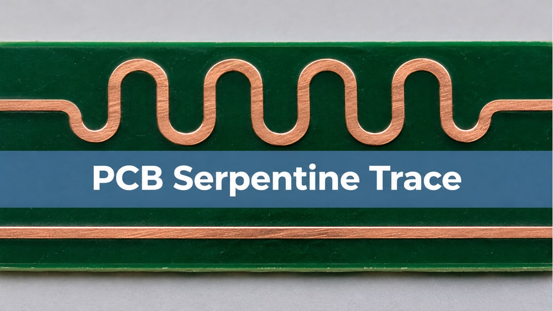
A serpentine trace folds extra conductor into a limited area. Adjacent turns can couple to each other, so the folded section may not behave like the same length of isolated straight trace. The effect depends on the geometry and signal spectrum rather than the shape name alone.
Consider a hypothetical source-synchronous interface with one signal arriving 24 ps early at the receiver. The designer can use a compact meander or route a more open detour. Both add the same CAD length on the same layer. The decision is which leaves acceptable arrival time and waveform quality.
Trace Length Matching
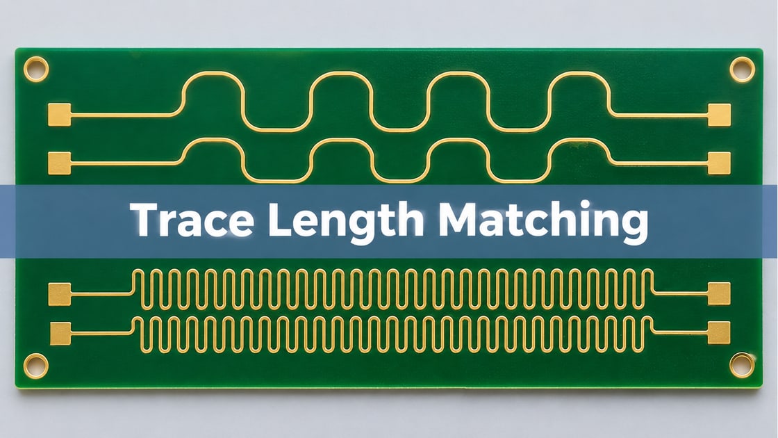
Use CAD length matching to screen the layout, then compare electrical arrival time at the relevant pins. Include package delay, via transitions and route layers when the interface timing model calls for them. Two equal trace lengths on different layers need not produce equal delays.
For the example, keep the vias and reference planes unchanged in both candidates. Correct only the early signal, and measure against the same reference signal and switching criterion. The Best Technology trace length matching guide covers the broader timing budget.
PCB Trace Propagation Delay
As a first estimate, multiply added length by the straight-trace propagation delay per unit length for the actual layer. If an illustrative straight route has 6 ps/mm of delay, 24 ps ÷ 6 ps/mm suggests 4.0 mm of added centerline. This calculation is a starting target, not the predicted delay of a coupled meander.
| Input | Example only |
| Early arrival | 24 ps |
| Straight trace estimate | 6 ps/mm |
| First added-length target | 4.0 mm |
| Electrical acceptance | Use the interface timing budget |
Do not reuse 6 ps/mm across all stackups. Use layer-specific data or a suitable field model and keep the package and board portions of the timing budget distinct.
PCB Trace Spacing
Define spacing between adjacent serpentine legs edge to edge, and note the width and distance to the reference plane. Close parallel runs and long coupled overlap can change both the delay and the impedance behavior. There is no single spacing multiplier that proves the path meets a particular timing budget.
When room is available, compare fewer, more open bends or a gently extended route with the compact geometry. Use a continuous reference plane and avoid creating a new coupling problem with nearby traces to make room for the tune.
PCB Crosstalk Simulation
Model the tuning section with its actual neighbors and return plane, not as a straight segment with the same length. Inspect the simulated transfer response or time-domain arrival, impedance discontinuities and relevant crosstalk. Coupling within one folded signal is a separate concern from coupling to an adjacent aggressor; both can matter.
| Candidate | Why try it | What can disqualify it |
| Tight meander | Fits a narrow corridor | Delay gain or impedance margin is poor |
| Open meander | Separates neighboring legs | Uses space needed by another route |
| Longer detour | Avoids tightly packed folds | Adds vias or changes reference path |
Compare candidates at the same electrical reference points. An apparently faster waveform caused by unequal fixture or launch models is not evidence about meander spacing.
Differential Pair Skew Compensation
In a differential pair, determine whether the problem is skew within the pair or delay between pairs. Adjusting one conductor can correct intra-pair skew, but a wide detour may also disturb pair coupling and create mode conversion. Routing both conductors together changes pair delay while preserving symmetry better, but does not selectively correct one conductor’s lead.
Keep the interface-specific limits and validate the differential waveform and mode conversion where they matter. Do not transfer a tuning prescription from a single-ended bus directly to a tightly coupled differential pair.
Serpentine Routing Guidelines
Compare both candidate routes against a straight reference and change one tuning variable at a time. Suppose a hypothetical controlled simulation predicts 18 ps added delay for a tight shape and 23 ps for an open shape, each with 4.0 mm added CAD length. The remaining error would be 6 ps or 1 ps, respectively. These values are illustrative, not measured or expected values for any design.
If both pass timing and signal quality, choose the geometry that fits without disturbing adjacent routes. If neither passes, reconsider the placement or route and rerun the analysis. Do not add another fold solely to remove a visual mismatch in CAD.
Time Domain Reflectometry PCB
Use time-domain reflectometry to check impedance changes through the tuning section. A reflection trace is not a direct one-way delay comparison between two receivers. For arrival time, use a suitable through measurement, a correctly referenced transmission model or a calibrated system measurement, depending on the design.
Release when the timing result, discontinuity limits and relevant neighboring-net or differential checks all pass. Keep the route, stackup, reference planes and model or test conditions linked to the verified revision so the result survives the next design change.
Frequently Asked Questions
Does a serpentine always add the expected delay per millimeter?
No. The straight-line estimate is useful for sizing the first candidate, but close folds can change effective delay. Simulate or measure the actual routed section and compare it with the same reference path. Keep the signal bandwidth and the reference planes consistent across candidates.
Is a larger gap always the best solution?
A larger gap can reduce interaction between adjacent legs, but it costs routing area and may push the route toward other signals or a broken reference. Compare the actual alternatives against timing and signal-quality limits. Prefer the one that passes without creating a new layout problem.
Can I tune two traces by matching their length on different layers?
Not without checking layer-specific delay. Different reference spacing and dielectric construction can change propagation, and vias add transitions. Use a timing model that includes those paths. A length report from the layout tool is a geometry check, not proof that the two signals arrive together.
Should I put the whole tune near the receiver?
There is no universal location. For a differential pair, think about where skew is introduced and how much unbalanced routing the correction creates. For a single-ended group, check neighboring signals and the return path. Compare the actual proposed positions in the model rather than relying on a default location.
Can a tightly folded trace be acceptable on a slow signal?
It can be acceptable if the actual edge, timing and noise limits are met. Repetition rate alone does not describe signal bandwidth; a low-rate interface can still use fast edges. Use the driver transition and interface constraints to decide how much validation the geometry needs.
What if the timing model and bench test disagree?
Check the reference planes, launch geometry, stackup and measurement thresholds before blaming the routing. Compare the same edge and operating condition, and account for fixture effects where necessary. Retain both records and resolve the difference before using the model to justify a marginal result.
Is the CAD tool’s differential tuning score enough for release?
No. The tool can show length and rule compliance, but the electrical result depends on stackup, coupling, transitions and the interface budget. Verify the actual differential response and skew where required. A clean length report does not certify that the tuned geometry preserves signal quality.
What files help with a serpentine routing review?
Send the routed section and neighboring nets, stackup and reference layers, trace dimensions, spacing, via details and the timing target. If possible, include both the compact and open alternatives. This gives the reviewer enough information to compare the real geometry rather than just the CAD length.
References
- Texas Instruments: High-Speed Interface Layout Guidelines
- Keysight: TDR and TDT Concepts
- Published research: Post-Route Alleviation of Dense Meander Segments
Discuss Your PCB Requirements
For a Best Technology fabrication review, send the stackup, routed tuning geometry and impedance requirements to sales@bestpcbs.com. Include both candidate layouts if you need to compare how the fabrication rules affect them.