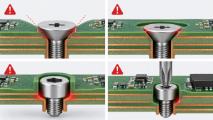
A backdrill must cut deep enough to leave a short via stub, but not so deep that it damages the last connected layer. Check both limits against the same surface datum. If the ranges do not overlap after tolerances, choosing a different nominal drill depth cannot fix the build.
What a Backdrill Removes
A plated through-hole can extend beyond the last layer that uses it. That unused conductive section is the stub. A larger drill removes the unused barrel from the entry side. Altium’s controlled-depth drilling documentation separates the residual-stub design rule from the drill settings.
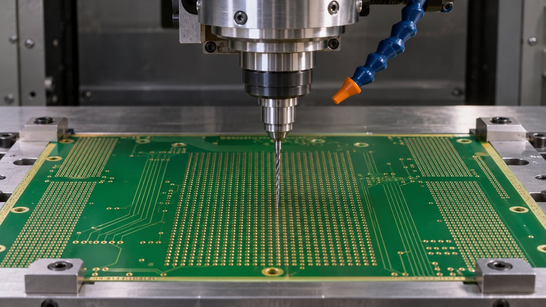
Use One Reference Surface for Every Dimension
Measure both the connected-layer position and effective cut depth from the agreed entry surface. Specify whether the cut depth refers to full barrel removal or another tool reference. A conical tip can extend deeper than the location where the barrel is fully removed.
Detailed Parameters for the Depth Budget
| Symbol | Example value | Meaning |
| — | — | — |
| L | 0.82–0.88 mm | Depth to protected connection |
| S | 0.20 mm max | Allowed residual stub |
| C | 0.05 mm min | Required clearance to protected connection |
| T | ±0.03 mm | Effective cut-depth variation |
| D | To be chosen | Nominal effective removal depth |
These are hypothetical inputs for a simplified model. They are not a manufacturing specification or a supplier’s tolerance. Here the agreed clearance is assumed to account for the cutter geometry; if it does not, include that geometry separately.
Shallow Cut vs Deep Cut
| Case | Risk | Bound to check |
| — | — | — |
| Shallowest removal | Too much unused barrel | Deepest connected layer |
| Deepest removal | Damage to protected copper | Shallowest connected layer |
| Larger tool diameter | Plane or neighboring copper damage | Lateral clearance along drill path |
Calculate the Lower Depth Bound
The shallowest actual cut in the model is D minus T. Its worst-case stub is 0.88 mm minus that cut depth. To leave no more than 0.20 mm, require D to be at least 0.88 − 0.20 + 0.03 = 0.71 mm.
Calculate the Upper Depth Bound
The deepest cut is D plus T. The nearest protected connection is at 0.82 mm, and the model requires 0.05 mm of clearance. That makes D no greater than 0.82 − 0.05 − 0.03 = 0.74 mm.
Example: A Nominal Cut Inside the Window
At a nominal 0.72 mm, the shallowest cut is 0.69 mm and the longest stub is 0.19 mm. The deepest cut is 0.75 mm, leaving 0.07 mm to the nearest connection. Both conditions pass the hypothetical limits. Ask the fabricator to confirm the real tool and layer-depth definitions.
What an Empty Window Means
If the maximum allowed stub were 0.15 mm, the lower bound would rise to 0.76 mm while the upper bound remains 0.74 mm. No nominal choice can satisfy both limits in this model. For a spreadsheet check with independent worst-case bounds, enter Lmax − S + T as the lower limit and Lmin − C − T as the upper limit. A negative difference between upper and lower bounds is a stop signal. Change a justified input such as the layer transition or use a different interconnect instead of choosing the midpoint.
Why to Check Drill Diameter Separately
Depth governs how far the drill travels, not its sideways reach. Verify the proposed diameter and positional allowance against nearby traces and plane copper throughout the drilled span. A feasible depth does not make an oversized lateral envelope acceptable.
Set the Stub Limit From the Actual Link
A short stub generally reduces its influence on the channel, but the allowed length depends on the link and design assumptions. Use the applicable interface guidance and channel analysis. Do not copy a number from another board without considering transition geometry and performance requirements.
Compare a Shorter Through-Via Transition With a Blind Via
A different signal layer can reduce the unused barrel before any backdrill is added. A blind via can avoid the long through-barrel but changes fabrication requirements. The BestPCBs backdrill guide covers those broader alternatives; compare them using your actual layer assignment.
Specify Physical Evidence Before Production
Agree on the entry side, drill pair, residual measurement datum and sample or coupon plan. Ask how depth and retained connection will be verified and what a section can demonstrate at the sampled location. For manufacturing notes and deliverables beyond the calculation, see the controlled-depth drilling DFM guide. Keep the approved stackup and release data together.
Send the Depth Budget for Review
Share the stackup, controlled nets, stop-layer protection and stub criteria with Best Technology.
FAQ
Is a shorter residual stub always better?
Electrically, shortening unused barrel can help the channel, but a tighter requirement can narrow the manufacturing window and raise the risk of cutting into a connection. Set the limit from the actual link and verify it alongside the minimum copper protection, rather than optimizing either number alone.
Can I specify just the stop layer?
A stop layer identifies the relevant part of the stackup, but does not by itself define an acceptable remaining stub or the measurement reference. Agree on the entry side, protected layer and residual criterion, then confirm how the fabricator interprets those details in the manufacturing output.
Is nominal board thickness enough for the depth calculation?
No. The depth to the connected layer depends on the build from the chosen entry surface, not only the overall board thickness. Request the layer depth range and its measurement convention. A board can meet overall thickness while a particular internal layer lies outside the position assumed in the model.
Does a designer’s DRC prove the hole can be made?
No. DRC checks the modeled design and selected rules. The physical result depends on actual fabrication tolerances, tool geometry and the measurement convention. Use the software result to locate and review the affected vias, then confirm the manufacturing window and acceptance evidence with the fabricator.
Can I backdrill from both sides?
It can be possible when unused barrel exists on both sides of a connected segment. Treat each entry side as its own depth budget, then verify that the two cuts preserve the required connections and copper clearances. Ask the fabricator how both sides should be represented in the outputs.
What if the depth window is very narrow but still positive?
A small positive range is a starting point, not a guarantee. Verify rounding, datum definitions, drill tip allowance and whether the quoted variation covers the actual process. Ask whether the drawing and inspection plan can resolve the remaining margin before accepting the proposed nominal setting.
Can a cross-section show the longest stub on the entire panel?
A section shows the geometry at the inspected location. It does not automatically establish the maximum across every via or panel. Agree on how representative samples are chosen, how the cut plane is positioned, and what additional process evidence supports acceptance of the affected lot.
Can I use the same backdrill depth for different via groups?
Only if the groups share compatible depth, geometry and clearance requirements. Different signal exit layers or entry sides can require different settings, even when the via holes look identical in plan view. Map each affected group to the approved stackup and check its worst-case limits separately.