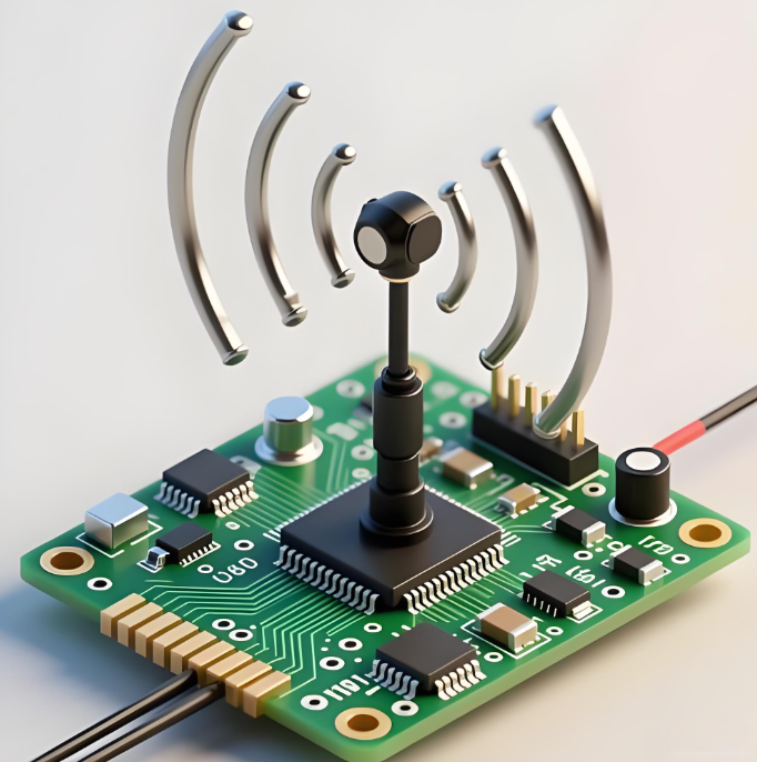
A quarter-wave monopole uses a conductive ground plane as the electrical image of its missing second half. A center-fed half-wave dipole contains both radiating arms, so it can operate without using the product chassis or PCB ground as its return structure.
Neither is universally better. The monopole is shorter and easy to integrate into a grounded product. The dipole occupies more space but is less dependent on RF PCB ground quality. The right choice follows from enclosure size, frequency, mounting, polarization, matching, and the final operating environment.
What Does Quarter-Wave Monopole vs Half-Wave Actually Compare?
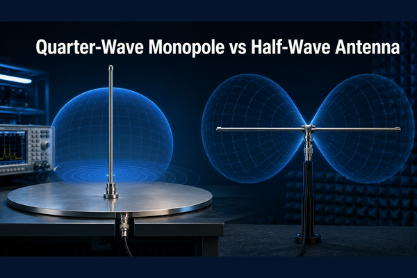
The useful comparison is a quarter-wave monopole against a center-fed half-wave dipole. They can produce similar radiation behavior, but create the required RF current path differently.
- Quarter-wave monopole: one conductor about one-quarter wavelength long, positioned above or beside an RF ground.
- Half-wave dipole: two conductors, each about one-quarter wavelength long, fed between their inner ends.
- Half-wave monopole: a different end-fed structure with high feed-point impedance; it is not another name for a dipole.
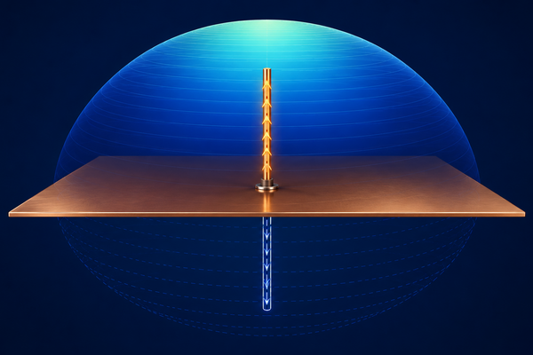
In the ideal monopole model, the conductive plane creates an electromagnetic image of the visible element. The element and its image behave much like the two arms of a dipole. The ground plane is therefore an active part of the antenna, not spare copper.
How Is Antenna Length Calculated?
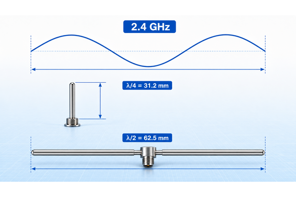
Free-space wavelength is λ = c/f, where c is approximately 299,792,458 m/s and f is frequency in hertz. Initial dimensions are c/(4f) for a quarter-wave element and c/(2f) for a half-wave dipole overall.
| Frequency | Wavelength | Quarter wave | Half wave |
|---|---|---|---|
| 433 MHz | 692.4 mm | 173.1 mm | 346.2 mm |
| 868 MHz | 345.4 mm | 86.4 mm | 172.7 mm |
| 915 MHz | 327.6 mm | 81.9 mm | 163.8 mm |
| 2.4 GHz | 124.9 mm | 31.2 mm | 62.5 mm |
| 5.8 GHz | 51.7 mm | 12.9 mm | 25.8 mm |
These are starting values. Conductor width, substrate, solder mask, enclosure plastic, battery position, ground geometry, and the user’s hand shift resonance. For a printed antenna, do not shorten the trace using FR4 Dk alone: part of its field travels through air. Start from a proven reference layout and retain copper that can be trimmed during prototype tuning.
Quarter-Wave Monopole vs Half-Wave Dipole: Key Differences
| Parameter | Quarter-wave monopole | Half-wave dipole |
|---|---|---|
| Structure | One λ/4 element plus RF ground | Two λ/4 arms |
| Overall radiator | About λ/4 visible | About λ/2 |
| Ground plane | Required for intended operation | Not required as a radiating arm |
| Ideal feed resistance | About 36.5 Ω | About 73 Ω |
| Feed | Usually unbalanced | Balanced; coax normally needs balun/choke |
| Product sensitivity | Strongly affected by ground/chassis | Less dependent on product ground |
| Best fit | Grounded embedded products | Ground-independent external antennas |
Why Does a Quarter-Wave Monopole Need a Ground Plane?
The ground plane provides the RF return-current path and the image current that lets a λ/4 element behave like half of a dipole. In a product, it may be continuous PCB copper, a vehicle roof, a metal chassis, radial wires, or a combination of PCB ground and conductive mechanical parts.
A small or fragmented ground changes impedance, resonance, efficiency, and pattern. RF current may be forced onto USB cables, coax shields, harnesses, or the user’s body. Return loss can still look respectable even while useful radiated power is poor. A dipole supplies its own second arm, although nearby metal and an unbalanced cable can still disturb it.
How Do Impedance and Matching Differ?
Most radios, coax connectors, and PCB transmission lines use 50 Ω, so either antenna may need matching. Monopole impedance can be adjusted through element geometry, feed position, ground dimensions, and radial angle. A dipole’s nominal 73 Ω value also moves with conductor diameter, installation height, and nearby material.
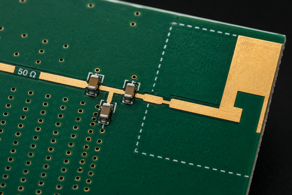
- Reserve a π-network footprint on embedded prototypes, even if the first build uses a zero-ohm link.
- Use a balun or common-mode choke when coax feeds a balanced dipole.
- Measure in the final mechanical assembly before locking values.
- Do not treat matching as a cure for a lossy radiator or inadequate ground.
A low VSWR only confirms limited reflected power at the feed. It does not prove good radiation efficiency or range.
Which Antenna Has More Gain and Range?
A free-space half-wave dipole has about 2.15 dBi theoretical maximum directivity. An ideal quarter-wave monopole over an infinite perfect ground can reach about 5.15 dBi because energy is confined to one hemisphere. That 3 dB difference should not be applied blindly to compact products.
Realized range depends on transmit power, realized gain in the required direction, efficiency, receiver sensitivity, polarization, matching and feed losses, mounting height, obstacles, and multipath. With a useful ground plane, a monopole is compact and effective. With a small or unpredictable ground, a properly fed dipole may be more repeatable.
How Do Radiation Pattern and Polarization Compare?
Both can give broadly omnidirectional azimuth coverage when vertical and kept clear of conductors. Their weakest directions are along the antenna axis. Installation often changes the pattern more than the ideal antenna type.
- Vertical radiators produce vertical polarization; a tilted device introduces mismatch.
- A horizontal dipole has nulls off its ends.
- Batteries, displays, shields, motors, and metal housings can create deep nulls.
- Uncontrolled feedline current makes the cable radiate and distorts measurements.
For handhelds, trackers, and sensors, review the three-dimensional pattern. Uniform coverage may matter more than a single peak-gain figure.
Which Antenna Is Better for PCB and Embedded RF Products?
A printed monopole is a sensible starting point when the PCB has adequate ground and the antenna can sit at a board edge. A dipole is attractive where product ground is limited or varies between host devices.
| Situation | Starting option | Reason |
|---|---|---|
| 2.4 GHz IoT device with adequate PCB | Printed monopole or IFA | Low BOM cost and direct integration |
| Very small sub-GHz PCB | External dipole or validated loaded antenna | λ/4 is long and ground may be inadequate |
| Metal enclosure | External antenna | The enclosure can shield an internal radiator |
| Vehicle installation | Roof-mounted monopole | The roof provides a useful ground plane |
| Ground-independent external antenna | Half-wave dipole | Both radiating arms are included |
| Body-worn product | Prototype and test both | Body loading detunes and absorbs RF |
PCB Layout Rules for a Quarter-Wave Monopole
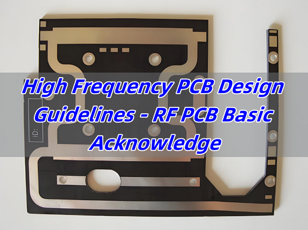
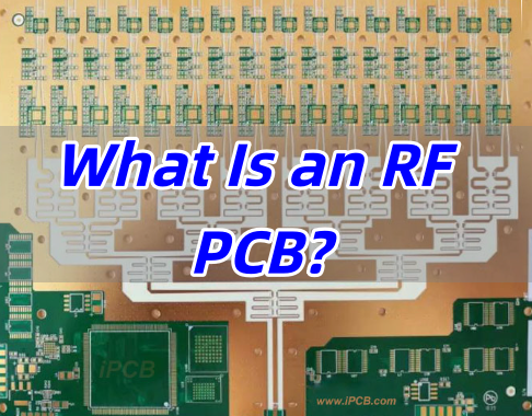
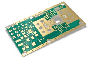
A printed monopole is an RF structure, not an ordinary trace. Copying only its outline while changing stack-up, ground size, feed geometry, or enclosure can produce a different antenna.
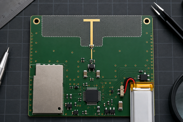
- Place the radiator at the board edge and preserve the reference orientation.
- Maintain the specified copper and component keep-out on every relevant layer.
- Keep batteries, displays, shields, cables, screws, and housing metal away.
- Route the feed as controlled 50 Ω microstrip or grounded coplanar waveguide.
- Use continuous RF ground under the feed, but not under a keep-out radiator.
- Add ground stitching vias at RF transitions and along grounded coplanar edges.
- Keep the matching network close to the feed and leave room for tuning.
- Add a conducted test connector or test path to early prototypes.
Common Antenna Failures and What They Really Mean
| Observed problem | Likely cause | Check |
|---|---|---|
| Resonance below target | Element too long or excess nearby capacitance | Trim the tip gradually in the final enclosure |
| Resonance above target | Element electrically short | Add length or revise matching |
| Good S11, poor range | Low efficiency or unintended cable/chassis loss | Measure OTA efficiency and packet performance |
| Performance changes when touched | Hand loading and inadequate isolation | Test realistic grip positions |
| Unit-to-unit range variation | Material, assembly, housing, or matching spread | Compare multiple production samples |
| Dipole pattern distorted | Common-mode coax current | Correct the balun or choke |
Tune after the complete mechanical assembly exists. An exposed PCB tuned on a bench can shift once it is placed beside a battery, coated, and closed inside plastic.
How Should the Antenna Be Tuned and Tested?
A vector network analyzer reveals feed impedance, return loss, and resonance. Over-the-air testing is still required to judge radiation performance.
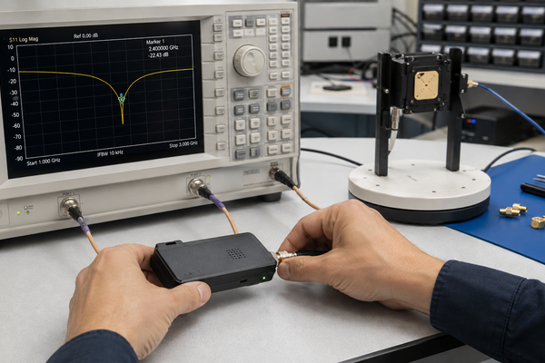
- Begin with a validated reference layout and preserve its stack-up, feed, keep-out, and ground assumptions.
- Measure the bare PCB and record S11 and impedance.
- Add the battery, display, shields, cables, screws, coating, and enclosure.
- Measure after each assembly stage to identify the source of detuning.
- Adjust physical length in small increments before changing several network parts at once.
- Optimize matching with production-grade RF capacitors and inductors.
- Check RSSI, packet error rate, throughput, or sensitivity in several orientations.
- Test several units and complete regulatory verification in maximum transmit mode.
For range-critical or positioning products, total efficiency and 3D radiation-pattern measurements provide far more information than return loss alone.
What Should Be Checked Before PCB Production?
- Operating bands, channels, and target bandwidth
- Final laminate, thickness, copper weight, and stack-up
- Controlled-impedance geometry and reference plane
- Antenna dimensions and manufacturing tolerances
- Keep-outs on every layer and solder-mask requirement
- Matching footprint and available RF component values
- Battery, shield, display, connector, and hardware locations
- Prototype RF test connector and tuning plan
- Enclosure material, spacing, and final-use orientation
Do not silently substitute laminate or board thickness after validation. Send the PCB manufacturer the approved stack-up, impedance requirement, antenna drawing, and keep-out notes together.
Frequently Asked Questions
Is a quarter-wave antenna better than a half-wave antenna?
Not universally. The monopole is compact when a good ground exists; the dipole is longer but less dependent on chassis ground.
Does a quarter-wave monopole have the same pattern as a half-wave dipole?
Over an infinite perfect ground, its upper-half pattern resembles a dipole. Finite ground changes the practical result.
Why does a quarter-wave monopole require a ground plane?
The plane supplies the RF return path and creates the electromagnetic image of the missing arm.
Can a quarter-wave antenna work without a ground plane?
It may radiate, but cables, PCB ground, or the enclosure become uncontrolled parts of the antenna.
Does a half-wave antenna need a ground plane?
A center-fed dipole does not, but a coax-fed version normally needs a balun or common-mode choke.
What is the impedance of a quarter-wave monopole?
About 36.5 Ω in the ideal model; real geometry and ground size can move it substantially.
What is the impedance of a half-wave dipole?
About 73 Ω for a thin free-space resonant dipole, with installation-dependent variation.
Is a monopole always half the length of a dipole?
Its visible element is about half the total dipole span, but its ground or counterpoise also occupies space and performs an electrical function.
How long is a quarter-wave antenna at 2.4 GHz?
The free-space value is about 31.2 mm; printed versions may be shorter after dielectric and enclosure loading.
How long is a quarter-wave antenna at 915 MHz?
About 81.9 mm in free space. Loading can reduce size at the cost of bandwidth or efficiency.
Does a longer antenna always provide more range?
No. Resonance, efficiency, impedance, orientation, and the full link budget determine range.
Can a PCB ground plane be too small?
Yes. It can reduce efficiency, shift resonance, distort coverage, and increase hand or cable sensitivity.
Why does an antenna fail inside its enclosure?
Plastic, adhesive, batteries, displays, shields, wiring, and fasteners change the electromagnetic environment.
Is VSWR enough to judge antenna quality?
No. It measures matching, not useful radiation. Evaluate efficiency and OTA performance too.
Should I use a monopole or dipole for a small IoT device?
Start with a proven printed monopole or IFA when adequate ground exists; consider a dipole or external antenna when ground is small or unpredictable.
Engineering Support for RF PCB Projects
The monopole is normally the smaller and lower-cost option, but ground, feedline, enclosure, and matching must work as one RF system. A dipole needs more span yet can be more predictable when reliable chassis ground is unavailable.
Before production, validate resonance, impedance, efficiency, coverage, enclosure effects, and unit-to-unit consistency. Lock the approved stack-up, controlled-impedance geometry, antenna keep-out, solder-mask requirement, and tuning provisions before Gerber release.
If you are sourcing PCB/PCBA manufacturing for prototyping, custom engineering, or volume production, contact the EBest engineering team at sales@bestpcbs.com.