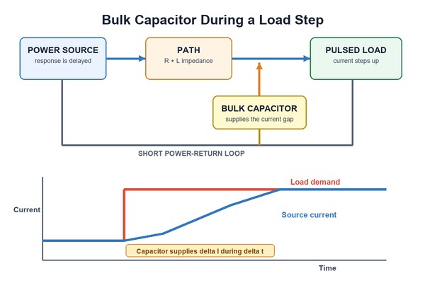
A bulk capacitor is an energy reservoir connected to a power rail. It supplies current when a load changes faster than the upstream source can respond, and it can absorb energy when the load releases current back onto the rail. The result is less voltage droop, overshoot, and low-frequency ripple at the circuit that must remain powered.
Calculating the value begins with the current-versus-time event, not a familiar capacitance such as 470 µF or 2,200 µF. The designer must define the current shortfall, its duration, the permitted rail movement, and the non-ideal losses in the capacitor and PCB path. The nominal value is selected only after those inputs are known, then confirmed on the assembled board.
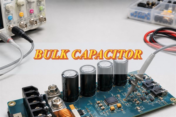
What Is a Bulk Capacitor and What Does It Do?
A bulk capacitor stores enough local charge to support a rail during a relatively high-energy event. The event may be a processor load step, a radio transmission burst, motor startup, a long cable feeding a board, a rectified supply between charging peaks, or energy returned by an inductive load.
The source cannot change its delivered current at the load terminals instantly. A regulator has finite control-loop bandwidth. Cables, connectors, fuses, planes, and vias add resistance and inductance. During the response gap, the capacitor supplies the difference between load demand and source current. When a load suddenly decreases or returns energy, the capacitor absorbs charge and slows the rail rise.
Its practical duties can include:
- Bridging a rising load: The capacitor supplies current until the regulator or remote source catches up. The design target is the minimum voltage observed at the protected load.
- Absorbing a falling or regenerative load: Stored or returned energy charges the capacitor. The maximum rail voltage, clamp strategy, and discharge path determine whether capacitance alone is sufficient.
- Reducing low-frequency ripple: The capacitor delivers charge between source-current pulses. The pulse interval and allowed ripple set the required effective capacitance.
- Isolating a board from a high-impedance feed: A local reservoir reduces the immediate current demanded through long leads or connectors.
The term bulk capacitor describes a circuit role rather than a specific component family. The correct part is the one that can supply or absorb the required charge at the rail voltage, temperature, ripple current, and service-life conditions of the product. That part may be an aluminum electrolytic, polymer, tantalum, ceramic, film capacitor, or a coordinated bank of several technologies.
What Is the Difference Between a Bulk Capacitor and a Decoupling Capacitor?
A bulk capacitor and a decoupling capacitor both control rail impedance, but they solve different parts of the same power-distribution problem. The useful distinction is the current event each capacitor must support and the length of its current loop.
| Comparison | Bulk capacitor | Decoupling capacitor |
|---|---|---|
| Primary job | Supplies or absorbs charge during a longer or higher-energy rail event | Supplies the fastest current edge at an IC power pin |
| Typical event | Regulator response delay, cable-fed load step, motor startup, radio burst, or rectified ripple | Logic switching, clock edges, and high-frequency IC current pulses |
| Placement | At a board input, regulator, load cluster, or other point where stored energy is needed | Immediately beside the relevant power and ground pins |
| Current loop | May include a rail segment, connector, regulator, or load group | Kept as short and low-inductance as the layout allows |
| Common technologies | Electrolytic, polymer, tantalum, ceramic, film, or a mixed bank | Usually small, low-inductance ceramic capacitors |
| Selection basis | Charge demand, support time, allowed rail movement, ESR, ripple current, and source response | Target impedance, edge rate, package inductance, pin location, and IC guidance |
| Can it replace the other? | No. Stored energy cannot overcome a long loop’s inductance during the fastest edge | No. A small local capacitor may not store enough energy for a longer load event |
There is no universal capacitance value that separates bulk from decoupling. A 22 µF ceramic may act as bulk capacitance on one device rail, while a board input may need several thousand microfarads. Many designs also use intermediate capacitance between the two. Review the complete impedance network because parallel values can create resonant peaks, and a very low-ESR bank can affect regulator stability.
What Parameters Do You Need Before Calculating Bulk Capacitance?
The calculation needs a defined electrical event and a voltage budget. Without those inputs, the result is only a copied rule of thumb and cannot show whether the protected rail stays within its operating limits.
- Rail voltage and permitted range: Record the nominal voltage, minimum acceptable voltage, maximum acceptable voltage, source tolerance, and any startup or regenerative peak. Separate the total allowed movement from the portion available for capacitor discharge.
- Current change: Record the initial load current, final load current, and the current the source can deliver during the event. The capacitor supports the shortfall, which may be smaller than the final steady-state load.
- Support time: Determine how long the current shortfall lasts before the regulator, upstream converter, battery, or remote supply responds. Use control-loop data, a load-step measurement, simulation, or a conservative system requirement. Switching frequency is not automatically the response time.
- Load slew rate and waveform: A 1 A change in 10 ns and the same change in 10 ms need different impedance control. Capture pulse duration, repetition rate, duty cycle, and whether the current ramps or steps.
- Source and distribution impedance: Include the cable, connector, fuse, copper path, vias, and protection elements between the source, capacitor, and load. Their resistance and inductance consume part of the voltage budget.
- Operating corners: Identify minimum input voltage, maximum load, cold-start ESR, hot-operation lifetime, tolerance, aging, and the physical configuration that produces the worst rail response.
- Energy direction: A rising load causes droop. Motor braking, solenoid release, load shedding, or cable disconnection can cause overshoot. Both directions may govern the same capacitor bank.
The voltage limit must be defined at the point where failure occurs. A stable waveform at the regulator does not prove that the processor pins, motor-driver supply, radio module, or board connector stays in range. State the measurement node before calculating the capacitor.
How Do You Calculate the Required Bulk Capacitor Value?
Calculate the charge that must be supplied during the interval before the source responds, then divide it by the voltage movement allocated to capacitor discharge. For an approximately constant current shortfall, the first estimate is:
C ≥ ΔI × Δt ÷ ΔVC
Here, ΔI is the current the capacitor must provide, Δt is the support interval, and ΔVC is the capacitive portion of the allowable rail change. If the load or source current ramps, calculate the area between the two current waveforms instead:
C ≥ ∫(Iload − Isource)dt ÷ ΔVC
Before using either expression, subtract the immediate resistive drop from the total voltage budget:
ΔVESR ≈ ΔI × ESR
PCB resistance and fast inductive spikes may require additional allowance. Texas Instruments’ load-transient capacitance guidance also treats the charge equation as an estimate that must account for converter response and non-ideal capacitor behavior.
A worked load-step example
Assume a 5 V rail experiences a 1.5 A load increase. The source needs 300 µs to supply the additional current, and the protected circuit permits a 0.25 V dip. The proposed capacitor and interconnect have 30 mΩ of effective series resistance during the event.
- Calculate the ESR step: 1.5 A × 0.030 Ω = 0.045 V.
- Find the remaining capacitive budget: 0.25 V − 0.045 V = 0.205 V.
- Calculate effective capacitance: 1.5 A × 300 µs ÷ 0.205 V = 0.00220 F, or approximately 2,200 µF.
- Convert the effective requirement into a part requirement: Add margin for tolerance, temperature, voltage dependence, aging, and source-response uncertainty. A nominal 2,200 µF part is not automatically sufficient.
- Check the complete rail: Verify regulator stability, startup, inrush, ripple current, overshoot, and the measured load-step response.
This is a hypothetical screening calculation, not a universal value. If the source current rises during the 300 µs interval, integrating the actual current difference can reduce the estimate. If the load edge is very fast, local ceramic capacitors are still required to control the leading edge while the bulk bank supports the longer pulse.
How Do ESR, ESL, Ripple Current, and DC Bias Affect the Actual Value?
They determine whether the nominal capacitance can control the real waveform without overheating or destabilizing the circuit. The calculated value is an effective in-circuit requirement; it must survive the electrical and environmental conditions of the finished assembly.
- ESR creates an immediate voltage step and heat: The current change multiplied by ESR appears before appreciable capacitive discharge. Lower ESR can reduce droop, but some regulators require a defined ESR range, and a low-loss bank connected through an inductive feed can ring.
- ESL limits the fastest response: Package geometry, leads, pads, vias, and trace length add inductance. A large capacitor located behind a narrow or long path may provide little help during the first part of a fast edge.
- Ripple current raises core temperature: AC current flowing through ESR produces heat. Compare the expected RMS ripple, frequency, ambient temperature, and cooling conditions with the manufacturer’s rating and lifetime model.
- DC bias can reduce ceramic capacitance: High-capacitance Class 2 MLCCs may retain only a portion of their labeled value at operating voltage. Murata’s DC-bias explanation shows why the part-specific bias curve belongs in the sizing calculation.
- Tolerance, temperature, and aging reduce the guaranteed minimum: Use the worst credible combination rather than adding nominal values. Parallel parts also may not share ripple equally when ESR, temperature, or interconnect impedance differs.
- Voltage stress and polarity set safe operating limits: Include line variation, startup overshoot, regenerative rise, ripple peaks, derating, and reverse-voltage exposure.
Aluminum electrolytic lifetime is especially sensitive to core temperature. Nearby power semiconductors, restricted airflow, and ripple heating can shorten service life even when room-temperature measurements look acceptable. Nichicon’s application guidance for aluminum electrolytic capacitors requires operation within the applicable voltage, ripple-current, temperature, polarity, and lifetime limits.
How Do You Choose the Right Type of Bulk Capacitor?
Choose the technology by matching its effective capacitance, impedance, ripple capability, voltage behavior, lifetime, package, and failure risks to the event defined earlier. The following options solve different constraints:
- Aluminum electrolytic for high capacitance at board inputs: It is often practical when the rail needs hundreds or thousands of microfarads at moderate cost. Check ripple-current rating, ESR at the coldest operating temperature, expected life at the measured case temperature, polarity, and vent clearance. Its larger size and finite service life may limit compact or high-vibration products.
- Aluminum polymer for low ESR and high ripple current: It can reduce the immediate ESR-related voltage step on compact low-voltage rails. Confirm rated voltage, surge tolerance, leakage, regulator stability, and the manufacturer’s ripple conditions. The tradeoff is usually higher cost and a narrower voltage range than many electrolytics.
- Tantalum or tantalum polymer for compact, stable capacitance: These parts can fit space-constrained rails that need predictable capacitance. Review voltage derating, surge and inrush behavior, failure mode, and protection requirements before approval.
- High-capacitance MLCCs for a low-inductance response: Ceramic banks help when low ESR and ESL matter, but the part-specific DC-bias curve may leave far less capacitance than the label suggests. Also check temperature class, board-flex cracking risk, acoustic behavior, and the current shared by each package.
- Film capacitors for high voltage, pulse current, or low loss: Film technology is useful when repetitive pulses, low dielectric loss, or voltage stress dominate the design. Confirm physical volume, termination-current capability, mounting, and vibration support because the required package may be large.
- A hybrid bank when one technology cannot cover the full impedance range: Combining a bulk electrolytic or polymer part with local ceramics can divide the energy and high-frequency duties. Model or measure the network so that anti-resonance and regulator stability are controlled rather than assuming more parallel values are always better.
After selecting the technology, lock exact manufacturer part numbers or reviewed alternates in the BOM. An unreviewed substitution can change capacitance under bias, ESR, ripple rating, lifetime, voltage margin, or package geometry even when the printed µF value is unchanged.
Where Should a Bulk Capacitor Be Placed on a PCB?
Place it where it closes the current loop responsible for the rail disturbance. Distance alone is an incomplete rule: the supply path, return path, switching device, source of the transient, and measurement point determine whether the capacitor is electrically close.
- At the board power entry: Put the reservoir after the connector, fuse, or protection stage when the board must ride through impedance in the external feed. Confirm that the source and protection path tolerate charging current.
- At a regulator input: Keep the high-current input loop short. A distant board-level reservoir cannot replace the local input capacitor required by the regulator data sheet.
- At a regulator output: Follow the permitted capacitance and ESR range, then connect the bank through short, wide power and return paths. Sense lines should observe the intended load point.
- Near a pulsed or regenerative load: Place local energy storage at the motor driver, solenoid driver, radio power amplifier, or other pulsed load when interconnect impedance would otherwise dominate the event.
- Across a distributed rail: Several reservoirs near separate load clusters can outperform one distant bank. Each bank still needs a defined role and an interaction check with the rest of the power-distribution network.
Route power and return as a pair. Avoid a narrow copper neck between the capacitor and load, and use enough vias for the transient current. For polarized or tall parts, make polarity clear, provide vent and mechanical clearance, keep heat sources away, and review shock or vibration when the product environment requires it.
How Does Bulk Capacitor Sizing Change for Different Applications?
The governing equation changes with the source waveform and energy path. The same charge relationship applies, but the current interval, voltage boundary, ripple spectrum, and failure consequence differ by application.
- Point-of-load regulator output: The regulator’s control-loop response defines the support interval. Both minimum and maximum output capacitance, ESR, load-step droop, and recovery behavior must remain inside the regulator’s stability requirements.
- Board input fed through a cable: Cable and connector impedance may make the local bank supply a pulse before the remote source responds. Cable length, source current limit, hot-plug behavior, inrush, and input-filter damping become part of the calculation.
- Motor or solenoid driver: Startup current can create droop, while braking or current interruption can return energy and create overshoot. Calculate both directions and determine whether a clamp, brake resistor, transient suppressor, or bidirectional source is also required.
- Rectified AC reservoir: The capacitor supplies the load between charging peaks. Use the rectified ripple interval, load waveform, line frequency, conduction angle, ripple-current rating, and safety requirements rather than a regulator load-step time.
- Radio, LED, or pulsed load: Pulse current, pulse width, repetition rate, and permitted modulation of the rail drive the required charge. Check cumulative ripple heating as well as the voltage movement during one pulse.
- Battery-powered product: Battery impedance, protection FETs, wiring, state of charge, and cold-temperature behavior may dominate the source path. Extra capacitance can help a short pulse but may increase connector spark, protection stress, or startup delay.
For every case, calculate at the node that must stay inside its voltage limit. A capacitor value derived for a board connector cannot automatically guarantee the voltage at a distant device rail.
What Happens If the Bulk Capacitor Is Too Large or Too Small?
Too little capacitance allows excessive droop, ripple, or overshoot; too much capacitance can create charging, stability, and stored-energy problems. The acceptable range is set by the source, regulator, protection circuit, and operating event rather than by a preference for the largest available value.
If the value is too small, the clearest warning signs are processor resets, excessive rail ripple, motor-driver undervoltage trips, regenerative overshoot, and high capacitor temperature because too few parts share the ripple current.
If the value is too large, check for excessive inrush, connector arcing, nuisance operation of a fuse or current limiter, failed startup, regulator instability, and an overly long discharge time. The extra stored energy can also increase fault stress, board area, and mechanical load.
The design therefore needs a verified capacitance range rather than a single minimum number. Confirm the lower limit with the worst load transient and effective capacitance, then confirm the upper limit against startup, inrush, stability, protection, and discharge requirements.
How Do You Verify Bulk Capacitor Performance on an Assembled PCB?
Verify the same event and limits used in the calculation. A capacitance meter or BOM check confirms a component property, but only a powered test at the correct node shows whether the assembled PCB controls droop, overshoot, ringing, and temperature.
- Reproduce the worst credible event: Apply the specified load step, pulse train, startup sequence, line condition, or regenerative event. Record current amplitude, edge rate, duration, repetition rate, input voltage, cable configuration, and temperature.
- Probe at the protected node: Measure power and return at the load pins or defined test points. Use a short oscilloscope ground spring or suitable differential probe so the measurement loop does not invent a spike.
- Interpret the waveform by region: The first voltage step points to ESR and path inductance. The following slope reflects capacitance and charge removal. Later recovery reflects the source and control loop.
- Test both current directions: Measure droop when the load rises and overshoot when it falls. For motors and inductive loads, include braking, reversal, and supply-disconnection cases.
- Check startup and faults: Confirm that the source starts reliably, current limiting does not nuisance-trip, connectors remain within rating, and stored energy discharges as required.
- Measure thermal stress: Record capacitor case temperature during sustained ripple at the worst ambient condition, then apply the selected part’s ripple and lifetime model.
- Lock the verified configuration: Record part numbers, quantities, locations, board revision, firmware or load state, test setup, and acceptance limits. Re-test alternates or layout changes that affect the power loop.
Match the correction to the observed waveform. A large instantaneous step calls for lower ESR or a shorter loop. A continuing slope calls for more effective capacitance or a faster source response. Ringing calls for impedance and stability analysis. Adding capacitance without identifying the failing region can hide one symptom while creating another.
What Are the Most Common Bulk Capacitor Selection Mistakes?
The most common mistakes come from replacing a defined electrical event with one catalog number or rule of thumb. Each error can be found before production by checking the calculation inputs, part curves, layout, and powered waveform together.
- Copying a value from another board: The other design may have a different rail, source response, current step, cable, or voltage limit. Recalculate from the present load event.
- Using nominal capacitance as effective capacitance: Tolerance, DC bias, temperature, and aging can reduce the available value. Use the part-specific minimum at the operating point.
- Giving the full droop budget to capacitance: ESR, copper resistance, connector resistance, and inductive spikes also move the rail. Reserve voltage margin for each known term.
- Replacing local decoupling with one large part: A bulk capacitor cannot overcome the inductance of a long loop during the fastest current edge.
- Ignoring the regulator’s capacitance limits: More capacitance or lower ESR can slow startup, trigger current limiting, or destabilize the loop.
- Sizing only for load increase: Motor braking, load release, or cable disconnection can raise the rail. Check whether energy must be clamped or dissipated.
- Checking ripple current at the wrong condition: Frequency, ambient temperature, airflow, and current sharing affect heating.
- Placing the part beside the load but routing it through a narrow loop: Physical proximity does not compensate for shared vias, necked copper, or a remote return path.
- Approving an alternate by µF and voltage alone: Package, ESR, ESL, ripple rating, life, surge behavior, and terminal geometry can change the result.
FAQs About Bulk Capacitors
Q1: Is a bulk capacitor always an electrolytic capacitor?
A1: No. Electrolytic capacitors are common because they provide high capacitance economically, but polymer, tantalum polymer, ceramic, film, or hybrid banks may serve the same role when their ratings suit the circuit.
Q2: Can power in watts determine the required bulk capacitance?
A2: No. Power alone does not define rail voltage, current change, support time, allowed droop, source response, ESR, pulse repetition, or returned energy. Calculate from the actual current-versus-time event and voltage limits.
Q3: Can several smaller capacitors replace one large bulk capacitor?
A3: They can when their combined effective capacitance, voltage rating, ripple capacity, ESR, ESL, layout, and lifetime satisfy the requirement. Parallel parts may lower impedance and distribute heat, but unequal paths can prevent equal current sharing and can introduce anti-resonance.
Q4: Should the bulk capacitor be placed before or after the voltage regulator?
A4: It depends on which rail event must be controlled. Input capacitance supports the switching stage and isolates source-path impedance. Output capacitance supports the regulated load and participates in loop stability. Many designs need both.
Q5: Does a bulk capacitor need a discharge resistor?
A5: Add a discharge path when stored voltage must fall within a defined time for safety, service, sequencing, or reliable restart. Balance discharge time against continuous power loss, and verify any discharge path already provided by the load or regulator.
Need help bringing a bulk capacitor design into production? Send EBest Circuit your rail voltage, load-step or ripple requirement, selected capacitor part number or approved-alternate limits, Gerber files, BOM, order quantity, delivery target, and test criteria. Our team can review the footprint, polarity, hole size, copper path, component availability, and assembly requirements together. Email sales@bestpcbs.com for a free DFM review and a quotation based on your actual board and production scope.