A PCB trace fuse is a deliberately narrowed copper conductor intended to open under a fault. It can break a circuit, but a narrow track alone does not provide a specified clearing time, interrupt rating or safe post-fault condition. Whether it protects the circuit depends on the available fault current, the finished copper geometry, heat flow into the board and evidence from destructive tests on representative boards. For safety-critical isolation, use a protection device with ratings that cover the actual fault.
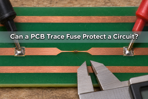
What Is a PCB Trace Fuse?
The fusible section is a reduced-width copper neck in series with the circuit. During normal operation it must carry the load without excessive voltage drop or heating. Under a fault, Joule heating may raise the weakest part of the neck until the conductor separates. The board material, however, is directly beneath that event. A visibly open copper trace is therefore not proof that the insulating board remains safe.
This is different from the discrete protection components covered in our PCB fuse selection guide. That guide addresses rated components, placement and replacement; the question here is whether the PCB copper itself can be treated as the sacrificial element.
How Does a Copper Trace Open During a Fault?
Current produces heat in the neck according to P = I²R. Resistance rises as copper warms, while heat flows into neighboring copper, laminate and air. A severe short may open a weak spot quickly; a modest overload may warm the entire area for a long time before anything opens. Neither outcome can be inferred from the normal-current trace-width calculation alone.
In published PCB trace-fusing experiments, the test traces were 6 in (152.4 mm) long and driven by a constant-current supply. One 15 mil, 0.5 oz trace opened in 2.75 seconds at 6 A with little visible board damage. A different 20 mil, 1.5 oz trace at 8.5 A took about 30 minutes and damaged the laminate. The long-trace results illustrate different failure behavior; they do not specify the opening time or dimensions of a short fuse neck.
Why Is Slight Overload More Dangerous Than It Looks?
A trace can remain continuous while its temperature approaches a level that degrades the resin or bond to the copper. In that experiment, the same 6 in trace carried 8.3 A for 120 minutes without opening, then was tested again at 8.4 A about 12 hours later and opened after 76 minutes. The trace had cooled between runs, but these were not independent samples differing only in current. The result illustrates slow thermal failure, not a precise trip threshold for another board.
For a real product, the difficult case may be the lowest available fault current, not the largest short-circuit current. If a source or cable limits the fault to a sustained intermediate level, the PCB can heat for minutes while remaining energized. Record both the fastest high-current opening and the slowest credible fault condition.
How Does Finished Copper Thickness Change the Result?
Specify the finished copper thickness at the neck, not just the nominal starting foil weight. Outer-layer plating can add copper; process variation changes the local cross-section. A thicker finished neck has lower resistance and can take more energy to open, while a thinner one may run hotter under the normal load. Both ends of the manufacturing range matter.
The experimental board set above used 0.5 oz foil plus plated copper on most samples. Its measured combined thickness ranged from 1.9 to 2.6 mil in the reported worst case. That range belongs to those boards only. At EBest Circuit (Best Technology), we would first review the customer’s specified layer build, plating route and achievable finished-neck dimensions for FR-4 PCB fabrication; we would not substitute a general copper-weight label for a fuse tolerance.
How Do Etching and Plating Change the Fuse Neck?
Photo-etching defines the actual neck width, and a small local narrowing can become the hottest point. Plating thickness also varies with panel position and pattern density. If the design relies on a narrow opening window, request a fabrication review of the finished minimum and maximum neck width and thickness on the chosen construction. A nominal CAD width is not an as-built measurement.
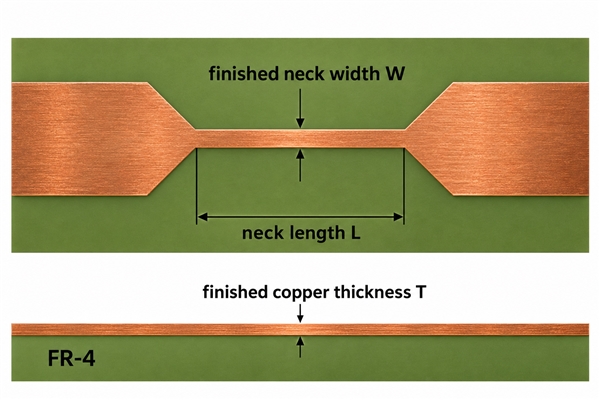
The plan view narrows the copper width at the neck. The side section keeps copper thickness uniform along that same trace; a locally thinned copper neck would be a different, separately specified process.
Keep the drawing unambiguous about the neck geometry. A solder bridge, unintended parallel layer path or copper pour connected across the neck can defeat the intended opening. Before assembly, check the actual exported copper and inspection data, not only the schematic symbol.
What Else Changes the Trace Temperature?
The two wide copper lands at the ends of a neck carry heat away. Nearby planes, vias, mask coverage, board thickness, enclosure airflow and component heat can change the temperature profile. A coupon floating in still air cannot represent a neck beside a power plane and a hot component inside a sealed housing.
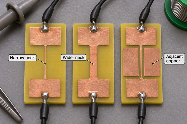
Hold these surroundings constant when comparing prototypes. If the production layout moves the neck or changes a plane, rerun the fault tests on that revision. The difference is not cosmetic: the local thermal path is part of the protection behavior.
Can Solder Mask or Assembly Change the Opening Behavior?
A mask opening changes the copper’s exposure to air and the chance that solder will wet the neck during assembly. Accidental solder buildup increases its cross-section and may delay opening. An uncovered neck can expose the surrounding area to contamination and mechanical contact. Neither mask-covered nor bare copper is automatically the right choice; build and test the construction that will ship.
At our PCB assembly stage, an agreed no-solder zone and the actual finished board artwork are more useful than a note saying merely “fuse trace.” The assembly and inspection plan should confirm that no reflow or manual operation bypasses or thickens the intended weak section.
Can a Blown Trace Leave a Conductive Carbon Path?
Yes, especially if the trace stays hot through a sustained overload. The resin may char or delaminate before copper separates. A gap in metal can coexist with damaged laminate, conductive debris or reduced insulation between energized conductors. It is incorrect to call the board safe solely because a continuity meter reads open at room temperature.
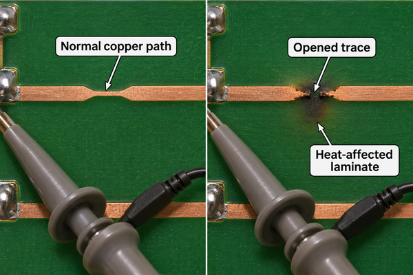
Charring can leave a leakage path even after the copper separates. The damaged area may extend under the trace or toward adjacent conductors, so the visible gap alone cannot define the affected area.
Can IPC-2152 Predict When a Trace Fuse Opens?
No. IPC-2152 addresses conductor sizing for current carrying and temperature rise in printed-board design. It helps screen the normal operating path. It does not give a validated opening-time curve, interrupting rating or post-fault insulation result for a chosen fuse neck. A wire-fusing formula is also only a starting estimate when the copper is bonded to a heat-sinking and potentially degradable PCB laminate.
Use calculations to reject obviously poor starting geometries, then determine opening behavior from the real stackup and representative samples. The question is not just “does the copper melt?” but “does it open before the rest of the circuit or board becomes unsafe under every fault in scope?”
How Should You Prototype and Test a PCB Trace Fuse?
Build test coupons and assembled boards with the same laminate, finished copper, mask, neck geometry and nearby copper as the production design. Include both low and high ends of the approved fabrication dimensions. For each planned fault, define the source voltage, source impedance, prospective current, ambient, enclosure state, applied duration and stop condition before energizing a sample.
| Test condition | Observe | Evidence to retain |
|---|---|---|
| Maximum normal load and specified inrush | Voltage drop, neck temperature, repeated-pulse survival | Waveform, thermal record and board revision |
| Lowest credible sustained fault current | Whether and when the neck opens; board heating while energized | Current/voltage trace, stop condition, visual inspection |
| Highest prospective short current | Opening time, arc/debris and damage containment | Waveform, test setup and post-event photographs |
| Worst-case geometry and thermal surroundings | Variation in opening time and normal-load rise | Measured neck width/thickness, location and ambient |
| After an opening event | Residual leakage and damaged insulation | Agreed insulation test result and disposition |
For example, a controlled test of the lowest credible fault starts with a measured neck cross-section and the customer’s stated supply limit. Apply that current with a bounded source, record current and voltage until opening or the predefined thermal stop, then inspect the laminate and perform the agreed insulation check. Compare all records with the customer-approved pass criteria. No universal current, time or leakage limit is implied by this example.
What Should Be Inspected After the Trace Opens?
Identify where copper separated, whether the gap is bridged by particles or solder, and whether the nearby resin is discolored, blistered or delaminated. Check adjacent traces and the underside when heat may have spread through the laminate. Do the product-specific insulation test only after the board has cooled and the source is safely isolated.
Record the fault waveform, photographs and measured insulation/leakage result against the product’s approved criterion. Quarantine the board until the fault source and damage extent are known. A board with charring, delamination or an uncertain leakage path is not returned to service by bridging the copper; repair or scrap disposition follows the approved product procedure.
When Is a PCB Trace Fuse Appropriate?
Start with the job the copper neck is expected to do:
- Characterize failure behavior: use a test coupon to observe opening, heating and laminate damage. The result is experimental evidence, not a protective rating.
- Make a controlled sacrificial board feature: consider it only if the product specification permits board replacement after a fault, the fault energy is bounded, and representative builds meet defined normal-load, opening and post-fault criteria across finished-dimension limits.
- Provide rated circuit protection: if the design requires specified interrupting capacity, isolation or certification, select a device rated for the prospective fault and verify its coordination with the PCB.
- Enable field replacement: if service must restore the product without replacing the board, plan for a suitable replaceable protective component and a fault-diagnosis procedure.
Document the chosen role and test limits on the drawing and in the system review. A successful coupon test does not authorize the same copper feature for a different source, layout or service requirement.
What Detailed Parameters Should a PCB Trace Fuse Drawing Specify?
The drawing must identify both the geometry that can be fabricated and the electrical conditions that must be validated. A nominal foil weight or CAD line width alone cannot define the opening response. The table separates design inputs from acceptance evidence; numerical limits come from the product specification and a reviewed fabrication process, not a universal fuse-trace chart.
| Parameter | Unit or required form | Why it matters | Acceptance evidence |
|---|---|---|---|
| Finished neck width, minimum and maximum | mm or mil | Sets local cross-section and current density | Fabrication measurement or approved coupon |
| Neck length and land transition | mm or mil plus drawing | Changes resistance and end cooling | Artwork and dimensional inspection |
| Finished neck copper thickness range | µm or mil, by layer | Foil plus plating determine actual cross-section | Cross-section or agreed process record |
| Laminate and mask construction | Material/grade and coverage drawing | Controls thermal path and post-fault insulation | Stackup and material records |
| Adjacent copper and via geometry | Clearance/distance in mm or mil | Can sink heat or create a parallel path | Released artwork and inspection |
| Normal current and inrush envelope | A and duration/profile | Sets no-open and temperature-rise conditions | Load waveform and thermal result |
| Minimum and maximum fault envelope | Source V, A, impedance and duration | Defines slow-heating and high-energy cases | Fault waveforms and opening-time distribution |
| Post-fault insulation criterion | Specified test V, leakage limit and environment | Checks that a copper gap is also a safe isolation state | Customer-approved test record |
PCB Trace Fuse vs SMD Fuse: Which Fits the Protection Requirement?
The decision turns on what must be proven after a fault. An SMD fuse selected for the actual voltage and prospective fault current has manufacturer time-current and interrupting data; a trace neck has no comparable rating unless the complete board design has been characterized for its specific use. The device still needs correct placement and fault coordination, so the comparison is not a promise that every SMD fuse will be adequate.
| Decision point | PCB trace fuse | Specified SMD fuse |
|---|---|---|
| Opening-time evidence | Must be measured on representative board variants | Use the exact part’s time-current and I²t data, then validate in-circuit |
| Fault voltage and interrupting capacity | No component interrupt rating by default | Select a part whose ratings cover the prospective fault |
| Heat and debris location | Failure occurs on the laminate | Failure occurs inside the device; board heating still requires review |
| After-fault service | Often requires board disposition | Part may be replaced after root-cause diagnosis |
| Best fit | Only a narrowly qualified sacrificial board feature | Defined overcurrent protection where rated data and replacement matter |
For most applications that require dependable isolation, the rated device is the clearer engineering choice. A fusible trace should not be described as equivalent simply because both can produce an open circuit.
What Should You Send for a Fabrication Review?
Send the released copper artwork, stackup, intended finished copper range, mask opening, neck dimensions, normal and fault-current envelopes, source characteristics and the proposed test criteria. For a simple build, our single- and two-layer PCB product route may be relevant; more complex constructions need a separate layer-by-layer review. We can assess manufacturability of the specified copper feature and coordinate bare-board and assembly inputs. We cannot promise a fuse clearing curve from a fabrication drawing alone.
If the design requires rated protection, include the exact fuse part number, footprint and fault requirements instead. A concise enquiry to sales@bestpcbs.com with those files lets us discuss a build and test plan without treating a prototype result as a universal safety approval.
PCB Trace Fuse FAQs
Should every production board be tested until the neck opens?
No. Opening is a destructive qualification test on representative boards or coupons. Production inspection can check the agreed neck dimensions, layer, mask and continuity without destroying every assembly.
What changes require another fault test?
Reassess changes to finished copper, neck geometry, laminate, mask, adjacent copper, enclosure cooling or the fault source. Each can alter the tested thermal path or available energy.
Can a blown copper link be bridged with solder?
Only if an approved service procedure permits repair after root-cause and insulation checks. A solder bridge changes the intended sacrificial feature; it is not a replacement for the original qualification.
Conclusion
A PCB trace fuse is appropriate only for a documented role that its finished-board tests actually support. Where the product needs a rated, replaceable protective element, specify and validate that device instead.