SPDT means single pole, double throw: one common contact can connect to either of two switched contacts. An SPDT switch is therefore useful when a circuit must select between two signal paths, operating modes or power sources. The three-terminal concept is simple, but a reliable design still depends on the contact arrangement, load type, actuator, footprint, switching sequence and PCB assembly method.
What Is an SPDT Switch?
An SPDT switch has one pole and two throws. The pole is the common moving contact, and the throws are the two alternative contacts it can reach. A typical mechanical SPDT device therefore has three electrical terminals. In one actuator position, COM connects to the first throw; in the other position, COM connects to the second. The two throw terminals are not normally connected to each other.
The term describes the contact function rather than the external shape. A toggle switch, slide switch, pushbutton, microswitch, relay contact set or semiconductor switch can all provide an SPDT function. The package, pinout, operating force, switching speed and electrical limits can be completely different, so the abbreviation alone is not enough to select a part.
What Do Pole and Throw Mean in SPDT?
A pole is an independently controlled circuit path. Single pole means the actuator controls one common path. A throw is one selectable contact position for that pole. Double throw means the common path can be routed to either of two contacts. This naming system also explains other common forms: SPST controls one path with one throw, while DPDT operates two SPDT contact sets from one actuator.
Do not interpret double throw as two outputs being powered simultaneously. In a standard SPDT function, the common contact selects one throw at a time. A center-off ON-OFF-ON switch adds a mechanical position in which COM connects to neither throw, but it is still a double-throw device.
How Does an SPDT Switch Work?
Inside a mechanical SPDT switch, the actuator moves a conductive contact between two stationary contacts. The electrical state changes from COM-to-throw-A to COM-to-throw-B. Many devices are break-before-make, meaning the first path opens before the second path closes. Some specialized parts are make-before-break and briefly connect both paths during transfer. That switching sequence must come from the datasheet because it affects source selection, analog signals and circuits that cannot tolerate an open interval or path overlap.
Mechanical contacts also bounce during actuation. Instead of changing state once, the contacts may make and break several times over a short interval. A lamp may not reveal the effect, but a microcontroller input can register multiple transitions. Hardware filtering, a Schmitt-trigger input or firmware debounce may be necessary when one operation must produce one digital event.
What Are COM, NO and NC Terminals?
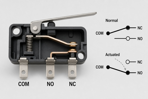
COM is the common terminal connected to the movable contact. On a snap-action switch or relay contact set, NC is connected to COM in the normal, unactuated state, while NO connects to COM after actuation. The normal state is defined by the manufacturer and may refer to an unpressed plunger, a de-energized relay coil or another specified rest condition.
A generic ON-ON toggle or slide switch may label its pins as common, position 1 and position 2 instead of NO and NC. Physical pin position is not a dependable identification method. Read the terminal diagram and pin numbering for the exact part. When markings are unclear, disconnect power and use continuity mode to identify which pin alternately connects to the other two.
How Do You Read an SPDT Switch Diagram?
An SPDT diagram shows one movable line starting at the common terminal and pointing toward one of two fixed contacts. The drawn position usually represents the normal or unactuated state, not necessarily the visual direction of the installed actuator. Pin numbers beside the symbol must be matched to the footprint and manufacturer drawing.
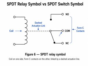
Symbol orientation can be rotated or mirrored without changing the electrical function. For a closer look at IEC and ANSI representations, different actuator symbols and the distinction between switch and relay drawings, see the BestPCBs guide to the switch SPDT symbol.
How Do You Wire an SPDT Switch?
Start by deciding what the common terminal should carry. For a mode selector, COM may connect to a microcontroller input while the two throws connect to defined logic levels through suitable pull resistors. For source selection, COM may feed the load while the throws connect to two approved sources. The arrangement can also be reversed when the circuit function requires one source to select between two destinations.
Before wiring, check that the switch rating covers the actual voltage, current and load type. A DC motor, relay coil, solenoid, lamp or capacitive input can produce inrush or inductive transients that are more severe than a steady resistive load. Use the protection recommended for the load, such as a flyback path for a DC coil or an appropriate snubber or suppression device. Never assume an AC rating can be applied unchanged to DC.
- Confirm the exact COM and throw pin numbers from the datasheet.
- Choose ON-ON, ON-OFF-ON or momentary action to match the required states.
- Keep low-level signals away from noisy power-switching traces.
- Define the state of every MCU input; do not leave a selected or unselected node floating.
- Verify both actuator positions with continuity before applying system power.
Which SPDT Switch Types Are Available?
The correct type depends on how the circuit is operated and what must be switched. The contact function may be the same, but the mechanical and electrical behavior is not interchangeable.
| SPDT type | Typical action | Useful design consideration |
|---|---|---|
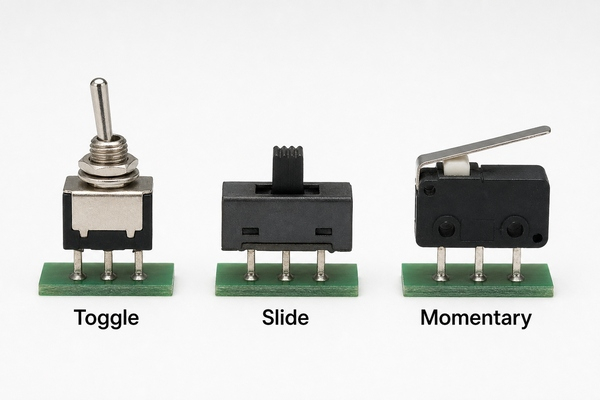
| Toggle switch | Maintained ON-ON or ON-OFF-ON | Panel clearance, lever access and mechanical support |
| Slide switch | Maintained position selection | Compact PCB mounting, travel direction and board-edge access |
| Momentary pushbutton or microswitch | Spring return after release | Operating force, overtravel, debounce and actuator alignment |
| SPDT relay contact | Electrically actuated changeover contact | Coil drive, isolation, contact rating and flyback suppression |
| Analog or RF SPDT IC | Electronic signal routing | On-resistance, bandwidth, insertion loss, isolation and control levels |
A mechanical SPDT switch creates galvanic metal-to-metal contact and may switch signals or power within its rating. An SPDT relay separates the control coil from the switched contact set. A semiconductor SPDT switch has no mechanical actuator and is selected by a logic signal; its specifications use parameters such as on-resistance, leakage, bandwidth or isolation. Treat these as different component classes even when the block diagram shows one input and two selectable paths.
Where Are SPDT Switches Used?
SPDT devices are used wherever one path must select between two alternatives. Common examples include operating-mode selectors, source selection, limit detection, interlocks, test routing, alarm contacts, audio signal selection and communication or instrumentation signal paths. Automotive and industrial systems also use sealed snap-action SPDT switches for position sensing, provided the environmental and load ratings are appropriate.
In low-voltage electronic products, a PCB-mounted slide or toggle switch often selects boot mode, battery or adapter input, local or remote control, or one of two signal routes. A microswitch can report two complementary states through NO and NC contacts. An SPDT relay can switch a load from a primary path to a backup path, while an analog or RF SPDT IC handles high-speed or low-level signals without a mechanical actuator.
How Does SPDT Compare with SPST and DPDT?
The decision depends on how many independent circuits must be controlled and how many selectable paths each circuit needs. Use the simplest contact form that supports the required states; extra poles and terminals increase footprint, wiring and verification work.
| Contact form | Independent poles | Throws per pole | Typical terminals | Typical use |
|---|---|---|---|---|
| SPST | 1 | 1 | 2 | Basic on/off control |
| SPDT | 1 | 2 | 3 | Select one of two paths |
| DPST | 2 | 1 | 4 | Open or close two circuits together |
| DPDT | 2 | 2 | 6 | Switch two paths together or reverse a paired connection |
An SPDT switch can be used as a simple on/off contact by using COM and one throw while leaving the other throw unconnected, but a purpose-built SPST part may be smaller or clearer. A DPDT part is appropriate when two isolated conductors must change together. Its suitability for a load still depends on the exact electrical rating; the extra pole does not automatically make it a higher-power switch.
Which SPDT Ratings Matter Most?
Contact configuration is only the first selection field. A datasheet should be checked for both electrical and mechanical limits. Values from one switch family cannot be generalized to all SPDT devices.
- Voltage and current rating: confirm AC or DC rating and the specified resistive, inductive, motor or lamp load.
- Minimum applicable load: important for dry-circuit and low-level signals because some contact materials need sufficient wetting current.
- Initial and end-of-life contact resistance: relevant to voltage drop, heat and small-signal integrity.
- Electrical and mechanical life: electrical life is measured under stated load conditions; mechanical life is normally measured without load.
- Insulation resistance and dielectric strength: define isolation performance between contacts and non-live parts.
- Operating force, travel and actuator life: determine user feel, mechanism compatibility and mechanical margin.
- Temperature, humidity and sealing: match the actual environment and cleaning process.
- Terminal and mounting style: choose through-hole, surface-mount, panel, wire lead or connector termination to fit assembly needs.
For example, official switch datasheets may specify contact resistance, insulation resistance, dielectric strength and separate mechanical and electrical durability values. Those numbers are test-condition dependent. Compare the intended load and operating environment with the exact datasheet rather than selecting a switch from contact form alone.
How Should an SPDT Switch Be Placed on a PCB?
Use the manufacturer-recommended land pattern and pin numbering, then verify it against the component drawing before releasing Gerber data. For through-hole switches, plated-hole diameter must accommodate the maximum terminal dimension plus insertion and plating allowance. For SMT switches, pad geometry, solder volume and coplanarity affect both solder quality and mechanical strength.
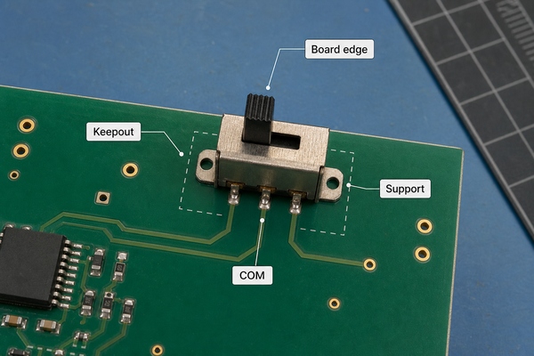
Place a user-operated switch where the actuator can be reached without transferring excessive force into the PCB. Board-edge placement may simplify enclosure access, but it reduces surrounding board material and can increase flexing. Add mounting support, enclosure features or a panel-mounted part when the expected force is too high for solder joints alone. Keep copper, components and enclosure walls outside the actuator travel and body keepout.
Route COM and the two throws according to signal sensitivity. Keep switch nodes short when they carry high-impedance analog signals, clocks or fast edges. Separate noisy switched loads from low-level logic, and provide return paths and suppression components close to the relevant devices. Compact interfaces may use an HDI PCB, while conventional controls commonly use an FR4 PCB; the footprint and mechanical requirements remain part-specific in either case.
How Do You Test an SPDT Switch with a Multimeter?
Remove circuit power and discharge stored energy before using continuity or resistance mode. If the switch is already on a PCB, parallel paths can affect the reading, so compare the schematic and isolate a terminal when necessary.
- Identify the three candidate terminals from the datasheet or board drawing.
- Place one probe on the suspected COM terminal and the other on one throw.
- Operate the switch and note the position that produces low resistance or a continuity tone.
- Move the second probe to the other throw and repeat the operation.
- Confirm that the two throws do not show continuity to each other in either normal position.
- Watch for unstable or unexpectedly high resistance that may indicate contamination, wear, a cracked joint or a wrong pin assumption.
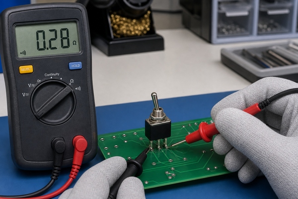
A slow multimeter may not display brief bounce or transfer timing. Use an oscilloscope or logic analyzer when the circuit depends on debounce duration, break-before-make interval or high-speed signal behavior.
What Common SPDT Circuit Problems Should Be Checked?
Start with pinout and contact state. A footprint mirrored from the wrong view can swap the common and throw terminals. A schematic may also use a generic symbol whose pin numbers do not match the selected component. Verify the manufacturer drawing, PCB footprint, placement orientation and assembled board together.
Intermittent behavior can come from contact bounce, insufficient wetting current, contamination, overload, inductive arcing, weak solder joints or PCB flex around the switch. If the fault occurs only under mechanical pressure, inspect the actuator alignment, housing interference and board support. If it occurs only with the load connected, compare inrush and transient conditions with the contact rating and protection network.
Production checks should cover solder fillet quality, terminal alignment, actuator movement and electrical state in every required position. Functional fixtures can verify that COM reaches the intended throw and that the product firmware interprets the state correctly.
How Do You Select an SPDT Switch for a PCB Assembly?
Define the required states first: maintained or momentary, ON-ON or ON-OFF-ON, and break-before-make or make-before-break. Then match the electrical load, minimum signal level, expected cycles, environment, actuator force, enclosure geometry and assembly process. Confirm that the supplier drawing includes an unambiguous footprint, pin numbering, body keepout and recommended soldering conditions.
The component package must also fit the production method. Through-hole switches may need selective or hand soldering after SMT reflow; surface-mount switches require appropriate paste apertures and support against operating force. EBest Circuit (Best Technology) provides PCB assembly covering SMT, through-hole and mixed assembly. Available inspection and test processes include 3D SPI, AOI, X-ray and functional testing, selected according to the board and assembly. Stated maximum capabilities remain subject to component package, board design, materials, quantity and engineering review.
FAQ About SPDT
What is an SPDT switch?
It is a single-pole, double-throw switch in which one common contact connects to either of two alternative contacts. A typical mechanical device has three electrical terminals.
What is the difference between an SPDT and DPDT switch?
SPDT controls one common path and selects between two throws. DPDT contains two poles that are operated together, with two throws available for each pole. A typical DPDT device therefore has six switched terminals.
What are the differences between SPST and SPDT switches?
SPST opens or closes one path and normally has two terminals. SPDT routes one common path to either of two contacts and normally has three terminals.
Is a 3-way switch an SPDT switch?
In North American building wiring, a mechanical 3-way switch commonly performs an SPDT changeover function. Mains wiring must follow the applicable electrical code and device instructions; PCB-level signal switching is a different installation context.
Can an SPDT switch be used as an SPST switch?
Yes. Use COM and one throw, leaving the other throw unconnected and safely isolated. A dedicated SPST switch may still provide a smaller footprint or clearer function.
Does an SPDT switch always have NO and NC terminals?
No. Snap-action switches and relay contacts often use COM, NO and NC labels relative to a defined normal state. Maintained ON-ON switches may identify the two throws by position instead. Always use the exact datasheet and continuity test.
Conclusion
SPDT describes a one-pole, two-throw contact function, but a successful design depends on much more than the abbreviation. Confirm the three-terminal pinout, switching sequence, actuator action, load rating, contact life, footprint, mechanical support and test method for the exact part. When the switch is integrated into a PCB assembly, layout and production controls should protect both the signal path and the soldered mechanical interface.
For support with PCB fabrication, component assembly or functional testing for a control product using SPDT devices, contact EBest Circuit (Best Technology) at sales@bestpcbs.com.