

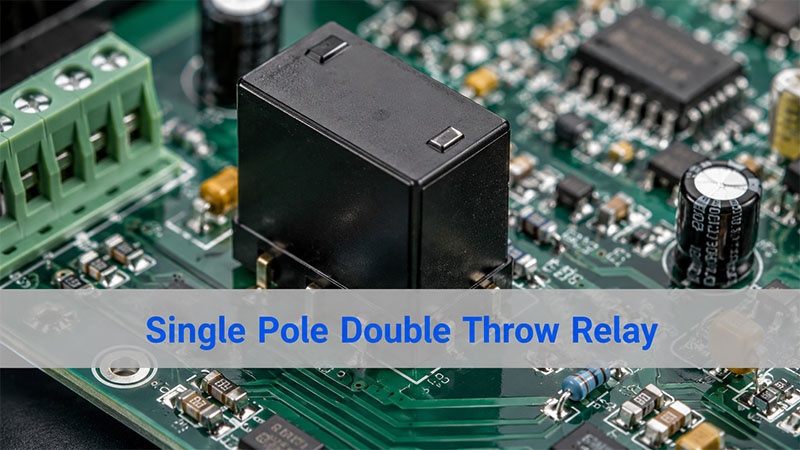
Single pole double throw relay is one of the most common relay types used to switch one circuit between two different output paths. In simple terms, it allows one input contact to connect with either of two output contacts, depending on whether the relay coil is energized or not.
You may also see it called an SPDT relay, changeover relay, or Form C relay. These names point to the same basic contact arrangement: one common terminal, one normally closed terminal, and one normally open terminal. This relay is widely used in control circuits, automotive electronics, power switching, signal routing, industrial automation, battery backup systems, alarm circuits, and PCB assemblies. For engineers, technicians, and electronics buyers, understanding how it works makes relay selection, wiring, troubleshooting, and PCB layout much easier.
In this guide, we will explain what an SPDT relay does, how it works, how to read its diagram and symbol, how to wire it, and how to choose the right relay for PCB or PCBA designs.
What Is a Single Pole Double Throw Relay?
A single pole double throw relay is an electromechanical or solid-state switching device that controls one circuit and switches it between two possible outputs.
The term can be broken down like this:
| Term | Meaning |
|---|---|
| Single Pole | The relay controls one common circuit path |
| Double Throw | The common contact can connect to either of two output contacts |
| Relay | An electrically controlled switch |
In a standard SPDT relay, there are three main contact terminals:
| Terminal | Full Name | Function |
|---|---|---|
| COM | Common | The moving contact or shared input/output terminal |
| NC | Normally Closed | Connected to COM when the relay is not energized |
| NO | Normally Open | Connected to COM when the relay is energized |
The relay also has two coil terminals in an electromechanical version. When voltage is applied to the coil, the internal armature moves and changes the contact connection from NC to NO.
So, in its resting state, COM connects to NC. Once the coil is powered, COM disconnects from NC and connects to NO.
This simple changeover action is why SPDT relays are so useful in electronic control circuits.
What Does a Single Pole Double Throw Relay Do?
A single pole double throw relay allows a circuit to choose between two paths.
For example, it can switch:
- A motor between forward and off control logic
- A signal between two output lines
- A device between main power and backup power
- A lamp between two control states
- A PCB circuit between normal operation and fault indication
The main value of an SPDT relay is not just turning something on or off. Its real advantage is changeover switching.
A simple ON/OFF relay only opens or closes one path. An SPDT relay gives you two possible states:
| Relay State | COM Connects To | Typical Meaning |
|---|---|---|
| Coil Off | NC | Default or standby path |
| Coil On | NO | Active or switched path |
This makes it helpful when the circuit needs a default connection before the control signal is applied.
For example, in a backup power system, the NC contact may connect to the main power line. When the control circuit detects a fault or change, the relay can switch COM to NO and route the circuit to an alternate power source.
How Does a Single Pole Double Throw Relay Work?
A standard electromechanical SPDT relay works through magnetic force.
Inside the relay, there is a coil, a movable armature, a spring mechanism, and three switching contacts: COM, NO, and NC.
When the coil has no voltage, the spring holds the armature in its default position. In this state, COM is connected to NC.
When voltage is applied to the coil, current flows through the winding and creates a magnetic field. This magnetic field pulls the armature toward the coil. As the armature moves, it breaks the COM-to-NC connection and makes the COM-to-NO connection.
When the coil voltage is removed, the magnetic field disappears. Then the spring returns the armature to its resting position, and COM connects back to NC.
Here is the basic operation:
| Coil Condition | Internal Action | Contact State |
|---|---|---|
| Coil not energized | Spring holds armature in default position | COM connects to NC |
| Coil energized | Magnetic field pulls armature | COM connects to NO |
| Coil de-energized again | Spring resets armature | COM returns to NC |
This action is fast, repeatable, and electrically isolated. The control side and the load side are separated, which allows a low-power circuit to control a higher-power circuit safely when the relay is properly rated.
Single Pole Double Throw Relay Diagram
A basic single pole double throw relay diagram usually shows the coil on one side and the switching contacts on the other side.
A typical SPDT relay has five pins:
| Pin Group | Description |
|---|---|
| 2 coil pins | Used to energize the relay |
| 1 COM pin | Common switching terminal |
| 1 NC pin | Normally closed contact |
| 1 NO pin | Normally open contact |
A simple contact diagram looks like this:
          NC
           |
           |
COM -------o
            \
             o
             |
             NO
In the relay’s normal state, COM touches NC. When the coil is energized, the internal contact moves and connects COM to NO.
A complete diagram may show the coil as a rectangle or loop symbol beside the contact structure:
Coil Side                  Contact Side

+ ----[ Coil ]---- -        NC
                            |
                            |
                   COM -----o
                             \
                              o
                              |
                              NO
This diagram helps users understand two important points:
First, the coil side controls the relay action. Second, the contact side switches the load or signal path.
The coil circuit and contact circuit are not the same electrical path in an electromechanical relay. This isolation is one reason relays are widely used in PCBs that must separate logic control from power switching.
Single Pole Double Throw Relay Wiring Diagram
A single pole double throw relay wiring diagram depends on what you want the relay to do. However, the basic wiring method is always built around COM, NO, NC, and the coil pins.
Here is a simple low-voltage switching example:
Control Side:

+12V Control Supply ---- Switch/Transistor ---- Relay Coil ---- GND


Load Side:

Power Supply + ---- COM

NC ---- Load A ---- GND

NO ---- Load B ---- GND
In this example:
- When the relay coil is off, power flows from COM to NC and turns on Load A.
- When the relay coil is on, COM switches to NO and turns on Load B.
- Load A turns off when Load B turns on.
This is the classic changeover function.
For a circuit where a load should only turn on when the relay is energized, use COM and NO:
Power Supply + ---- COM
NO ---- Load ---- GND
For a circuit where a load should stay on by default and turn off when the relay is energized, use COM and NC:
Power Supply + ---- COM
NC ---- Load ---- GND
This is useful for safety loops, alarm circuits, and default-on control paths.
Before wiring, always confirm the relay’s pinout from the datasheet or case marking. Pin arrangements can vary between manufacturers, even when the relay has the same voltage and contact form.
Single Pole Double Throw Relay Schematic and Symbol
In a schematic, an SPDT relay symbol usually includes two parts: the coil and the changeover contact.
The coil is drawn as a rectangle or winding symbol. The contact section shows COM switching between NC and NO.
A simplified schematic symbol looks like this:
        Relay Coil
A1 ----[      ]---- A2


        NC
        |
COM ----o
         \
          o---- NO
The slanted line represents the movable contact. In the normal position, it touches NC. When the coil is energized, it moves toward NO.
You may also see labels such as:
- A1 / A2 for coil terminals
- COM / C for common
- NO for normally open
- NC for normally closed
- Form C for SPDT contact form
In relay datasheets, the schematic may also include polarity marks if the relay has an internal diode, LED, or surge suppression component. This detail matters because a relay with an internal diode must be connected with the correct coil polarity.
For PCB design, the schematic symbol should match the physical footprint. A mismatch between schematic pins and PCB pads is a common source of relay assembly errors.
Single Pole Double Throw Relay Pinout: COM, NO, and NC
The most important part of an SPDT relay pinout is identifying the COM, NO, and NC terminals correctly.
Here is what each terminal means in practical use:
| Terminal | State When Coil Is Off | State When Coil Is On | Common Use |
|---|---|---|---|
| COM | Connected to NC | Connected to NO | Main input or output path |
| NC | Connected to COM | Disconnected from COM | Default-on circuit |
| NO | Disconnected from COM | Connected to COM | Active-on circuit |
In many small PCB relays, the five pins are arranged in a compact rectangular pattern. Automotive relays often use numbered terminals. Common automotive relay numbering may include:
| Terminal Number | Typical Meaning |
|---|---|
| 85 | Coil |
| 86 | Coil |
| 30 | COM |
| 87 | NO |
| 87a | NC |
This numbering is common, but it should not replace datasheet verification. Some relays may use different layouts, especially signal relays, telecom relays, power relays, and latching relays.
A quick continuity test with a multimeter can also help identify terminals:
- Find the two coil pins by measuring coil resistance.
- Find the pair that has continuity without coil power. That pair is COM and NC.
- Energize the coil with the rated voltage.
- The terminal that now connects to COM is NO.
This method is useful during troubleshooting, but for production design, the datasheet remains the correct source.
Single Pole Double Throw Relay Circuit Example
A common SPDT relay circuit uses a microcontroller or transistor to control a load. Since most microcontroller pins cannot drive a relay coil directly, a transistor driver is usually added.
A basic control circuit includes:
- Microcontroller output pin
- Base or gate resistor
- NPN transistor or MOSFET
- Relay coil
- Flyback diode
- External load circuit
Example structure:
Microcontroller Pin ---- Resistor ---- Transistor Base/Gate

Relay Coil + ---- +V
Relay Coil - ---- Transistor ---- GND

Flyback Diode Across Relay Coil
The relay contacts then switch the load:
Power Source ---- COM

NO ---- Load ---- GND
NC ---- Optional Default Load ---- GND
When the microcontroller output turns on the transistor, current flows through the coil. The relay energizes and COM switches from NC to NO.
The flyback diode is important in DC relay circuits. When the coil is turned off, the magnetic field collapses and creates a voltage spike. The diode gives this energy a safe discharge path and helps protect the transistor, microcontroller, and nearby PCB traces.
For AC loads or high-current switching, additional protection may be needed, such as an RC snubber, MOV, TVS diode, contact arc suppression, or proper creepage and clearance spacing.
12V Single Pole Double Throw Relay and Other Common Coil Voltages
A 12V single pole double throw relay is one of the most common types, especially in automotive electronics, low-voltage control boards, battery systems, lighting controls, and industrial modules.
However, SPDT relays are available in many coil voltage options.
| Coil Voltage | Common Application |
|---|---|
| 3V | Portable electronics, battery-powered modules |
| 5V | Microcontroller boards, Arduino-style projects, digital control PCBs |
| 9V | Small control circuits |
| 12V | Automotive, industrial control, LED lighting, battery systems |
| 24V | PLC systems, industrial automation, control cabinets |
| 120V AC | Appliance control, HVAC, mains-powered equipment |
| 230V AC | Industrial and regional mains-control circuits |
Coil voltage is not the same as contact rating. A relay may have a 12V coil but switch a much higher load voltage through its contacts, as long as the load remains within the relay’s rated contact voltage and current.
For example, a 12V relay may be rated to switch 250VAC at a specific current. Still, the exact rating depends on the contact material, relay structure, safety approval, load type, and switching frequency.
When selecting a relay, check these points:
- Coil voltage
- Coil current
- Contact voltage rating
- Contact current rating
- AC or DC load type
- Resistive or inductive load
- Contact arrangement
- Mechanical life
- Electrical life
- PCB footprint
- Operating temperature
- Safety approvals
For PCB or PCBA projects, relay height, pin pitch, soldering method, and insulation distance should also be reviewed early in the design.
Single Pole Double Throw Solid State Relay vs Electromechanical Relay
A single pole double throw solid state relay performs changeover switching without moving mechanical contacts. Instead, it uses semiconductor devices such as MOSFETs, optocouplers, triacs, or photovoltaic drivers.
The main difference is the switching mechanism.
| Feature | Electromechanical SPDT Relay | SPDT Solid State Relay |
|---|---|---|
| Switching Method | Moving metal contacts | Semiconductor switching |
| Isolation | Coil-to-contact isolation | Optical or electronic isolation |
| Speed | Moderate | Fast |
| Contact Wear | Yes, over time | No mechanical contact wear |
| Audible Click | Yes | No |
| Leakage Current | Usually near zero when open | May have small leakage |
| Contact Resistance | Low metal contact resistance | Depends on semiconductor device |
| Load Type | AC/DC depending on relay | Must match SSR output type |
| Cost | Often lower | Often higher |
Electromechanical relays remain popular because they provide true contact isolation, low off-state leakage, and clear contact behavior. They are also easy to understand, test, and replace.
Solid state relays are often chosen when the application needs silent operation, long switching life, high-speed switching, or resistance to vibration.
For PCB design, the choice depends on load type, switching speed, heat generation, leakage current, expected lifetime, and available board space. In many industrial and automotive designs, mechanical SPDT relays are still a practical and economical choice.
Single Pole Double Throw Relay vs SPST, DPST, and DPDT Relay
Relay names can look confusing at first, but the logic becomes simple once you understand poles and throws.
- Pole means the number of independent circuits being controlled.
- Throw means the number of output positions each pole can connect to.
Here is a practical comparison:
| Relay Type | Full Name | Contact Function | Best Used For |
|---|---|---|---|
| SPST | Single Pole Single Throw | One circuit, one output path | Simple ON/OFF control |
| SPDT | Single Pole Double Throw | One circuit, two output paths | Changeover switching |
| DPST | Double Pole Single Throw | Two circuits switched ON/OFF together | Switching two lines at the same time |
| DPDT | Double Pole Double Throw | Two circuits, each with two output paths | Polarity reversal, dual changeover control |
An SPST relay is like a basic switch. It opens or closes one circuit.
An SPDT relay can switch one common line between two outputs.
A DPST relay works like two SPST relays operated together.
A DPDT relay works like two SPDT relays operated together.
This is why a double pole single throw relay should not be confused with an SPDT relay. DPST controls two separate circuits but only provides one throw for each circuit. SPDT controls one circuit but gives it two throw positions.
For an information-focused article, it is useful to include DPST and DPDT in a comparison section, but the main topic should stay centered on SPDT relay operation.
Where Is a Single Pole Double Throw Relay Used?
SPDT relays are used anywhere a circuit needs to switch between two states or two paths.
Common applications include:
| Application | How the Relay Is Used |
|---|---|
| Automotive electronics | Switching lights, horns, fans, pumps, or accessories |
| Battery backup systems | Changing between main power and backup power |
| Industrial control | Routing control signals or switching loads |
| Alarm systems | Default closed safety loops or triggered outputs |
| HVAC control | Fan, compressor, or mode switching |
| Test equipment | Signal path selection |
| Audio circuits | Channel switching or mute control |
| Lighting control | Switching between modes or power paths |
| PCB control boards | Logic-controlled load switching |
In automotive circuits, a 12V SPDT relay is especially common because vehicle electrical systems are usually based around 12V control power.
In industrial electronics, 24V relays are common because many control cabinets and PLC systems use 24VDC control voltage.
In PCB assemblies, smaller signal relays may be used for low-current switching, while power relays are chosen for higher load current.
How to Choose a Single Pole Double Throw Relay for PCB or PCBA Design?
Choosing the right relay is not only about matching the coil voltage. For a reliable PCB or PCBA design, the relay must match the electrical, mechanical, thermal, and manufacturing requirements of the project.
Start with the coil voltage.
The coil voltage should match the control circuit. For example, a 5V relay can work well with logic-level boards when the driver circuit provides enough coil current. A 12V relay is common in automotive or battery-powered systems. A 24V relay is common in industrial automation.
Check the contact rating carefully.
The contact rating must support the load voltage and current. Also, pay attention to whether the load is resistive, inductive, capacitive, or motor-based. Inductive loads can create arcs and voltage spikes, so they usually need more protection.
Review the relay footprint.
For PCB mounting, the pad size, pin pitch, hole diameter, body outline, and keep-out area must match the selected relay. A good footprint reduces soldering defects and assembly variation.
Plan creepage and clearance.
When a relay switches high voltage, the PCB layout must provide enough distance between low-voltage control circuits and high-voltage load circuits. This matters for safety, reliability, and compliance.
Add coil protection.
For DC coils, a flyback diode is often used. In faster release circuits, a TVS diode or Zener clamp may be better because a standard diode can slow relay release time.
Consider contact protection.
For motor loads, solenoids, transformers, and other inductive loads, add suitable suppression. Options include RC snubbers, MOVs, TVS diodes, or load-side protection circuits.
Think about production testing.
For PCBA manufacturing, test points can be added near the coil driver and relay contacts. This helps with ICT, functional testing, and troubleshooting.
Confirm operating environment.
Temperature, humidity, vibration, dust, and switching frequency all affect relay performance. Automotive, medical, industrial, and outdoor lighting products may need stricter validation.
For EBest Circuit, relay-related PCB and PCBA projects usually require attention to footprint accuracy, soldering quality, BOM verification, test coverage, and DFM review. A relay is a familiar component, but its layout and load path can strongly affect long-term reliability.
Common Design Mistakes With Single Pole Double Throw Relay Circuits
Even though SPDT relays are simple components, mistakes can still happen during schematic design, PCB layout, wiring, or assembly.
Here are several common issues to avoid.
| Mistake | Result | Better Practice |
|---|---|---|
| Confusing NO and NC | Load works in the opposite state | Verify the contact diagram before wiring |
| Ignoring coil current | Microcontroller pin may be damaged | Use a transistor or MOSFET driver |
| No flyback diode on DC coil | Voltage spike may damage control circuit | Add diode, TVS, or clamp circuit |
| Wrong PCB footprint | Assembly failure or misconnection | Match datasheet pinout to footprint |
| Underrated contact current | Contact overheating or early failure | Select rating with proper margin |
| Poor spacing for high voltage | Safety and reliability risk | Follow creepage and clearance rules |
| No suppression for inductive load | Contact arcing and EMI | Use snubber, MOV, or diode protection |
| Routing high current through thin traces | Heat rise or voltage drop | Calculate trace width and copper weight |
For production boards, the relay should also be reviewed during DFM and DFT. This is especially important when the relay switches high current, high voltage, or safety-related circuits.
In closing, a single pole double throw relay is a practical changeover switching device that connects one common terminal to either a normally closed or normally open terminal. This makes it more flexible than a simple ON/OFF relay and useful in many control, power, signal, automotive, and PCB applications.
For a strong understanding, focus on five key points: COM, NO, NC, coil operation, and contact rating. Once these are clear, relay diagrams, wiring diagrams, symbols, and circuit examples become much easier to read.
For PCB and PCBA projects, relay selection should also include coil voltage, load rating, footprint accuracy, protection circuits, creepage and clearance, soldering process, and functional testing. A relay may look like a small component, but it often controls critical circuit behavior. Careful design and manufacturing review can make the final product safer, cleaner, and more reliable.
FAQs About Single Pole Double Throw Relay
What Is the Difference Between SPDT and Single Pole Double Throw Relay?
SPDT and single pole double throw relay mean the same thing. SPDT is simply the abbreviation. “Single pole” means one common circuit is controlled. “Double throw” means that common contact can switch between two output contacts.
What Are COM, NO, and NC on an SPDT Relay?
COM is the common contact. NO means normally open, and NC means normally closed. When the relay is not energized, COM connects to NC. When the relay is energized, COM connects to NO.
Is a Single Pole Double Throw Relay Normally Open or Normally Closed?
An SPDT relay has both normally open and normally closed contacts. That is why it can support two circuit states. You can use COM and NO for active-on switching, or COM and NC for default-on switching.
What Is a 12V Single Pole Double Throw Relay Used For?
A 12V SPDT relay is often used in automotive electronics, battery control systems, LED lighting, low-voltage control boards, alarm circuits, and small industrial modules. It uses a 12V coil to switch the relay contacts.
Can a Single Pole Double Throw Relay Switch AC and DC Loads?
Yes, many SPDT relays can switch AC or DC loads, but the rating is different for each type. DC switching is often harder on contacts because arcs do not self-extinguish as easily as AC arcs. Always check the relay datasheet.
Is a Single Pole Double Throw Relay the Same as a Changeover Relay?
Yes. A changeover relay is another common name for an SPDT relay. The term describes how the common contact changes over from NC to NO when the relay coil is energized.
What Is the Difference Between SPDT and DPDT Relay?
An SPDT relay controls one circuit and switches it between two outputs. A DPDT relay controls two circuits, and each circuit can switch between two outputs. A DPDT relay is similar to two SPDT relays operated together.
Do I Need a Diode for a Single Pole Double Throw Relay?
For a DC relay coil, a flyback diode or another suppression component is strongly recommended. It helps absorb the voltage spike generated when the coil turns off and protects the driver circuit.
You may also like


Tags: Relay PCB Assembly, Single Pole Double Throw Relay, SPDT Relay