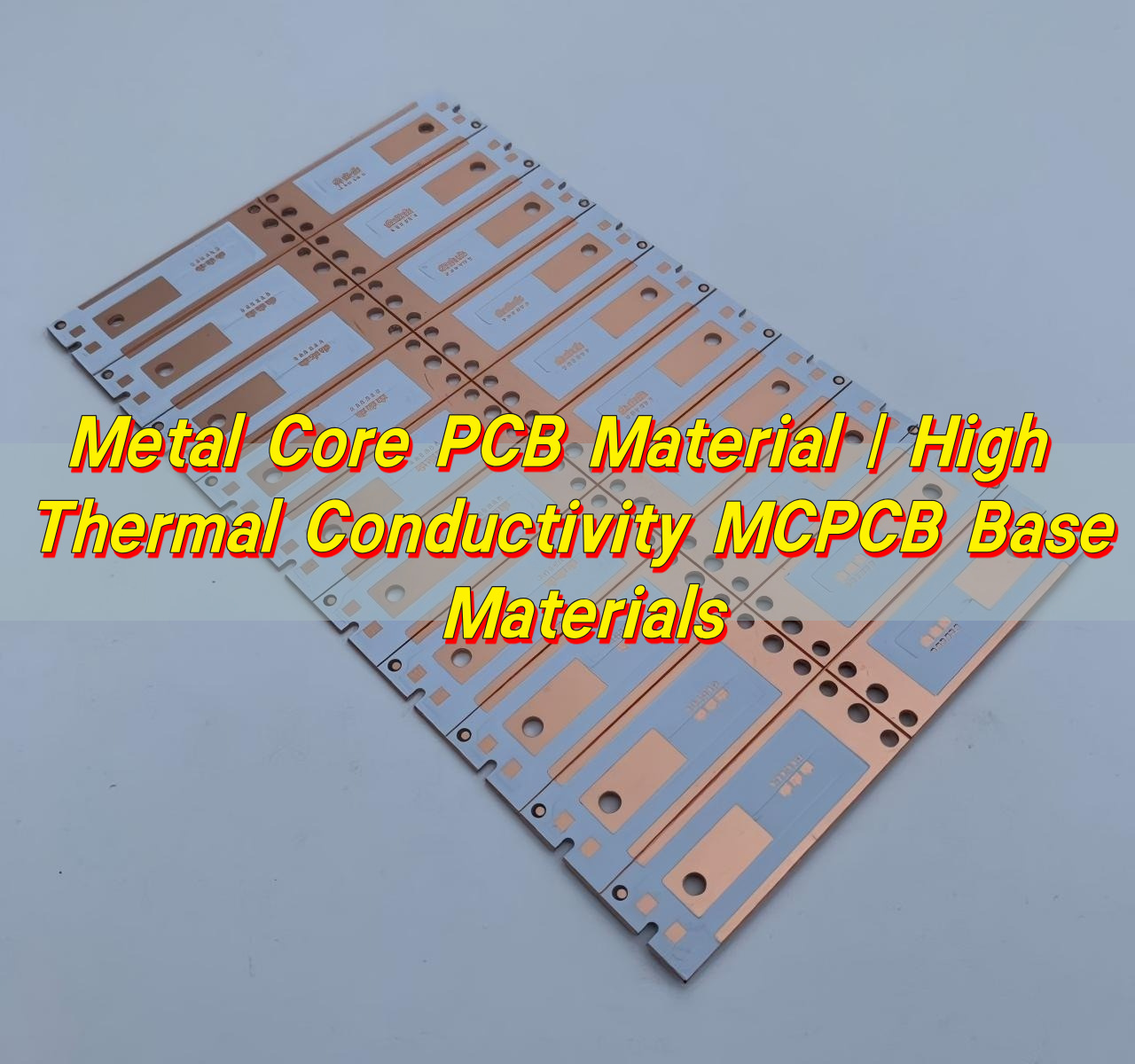
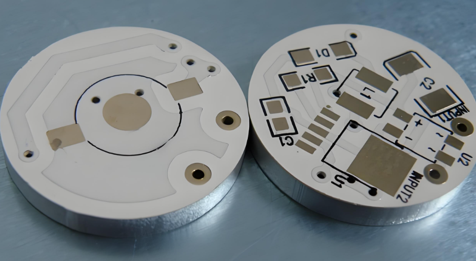
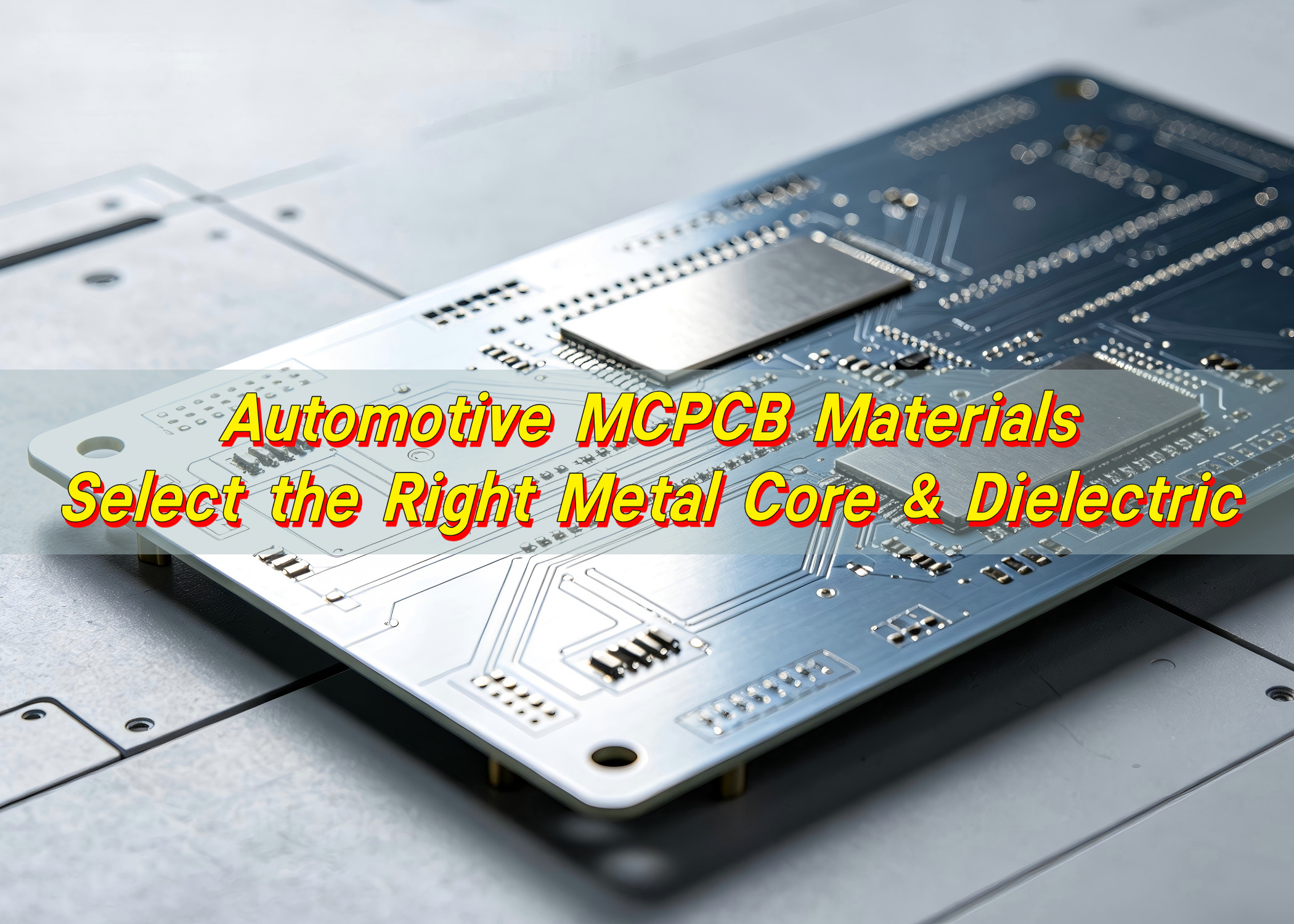
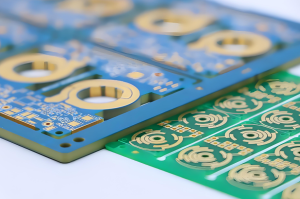
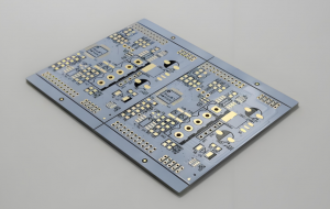
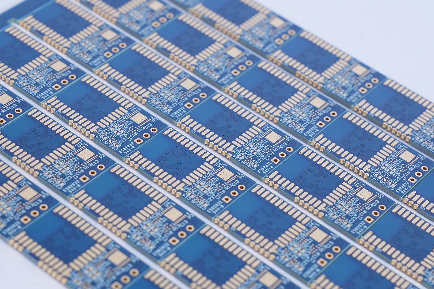
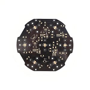
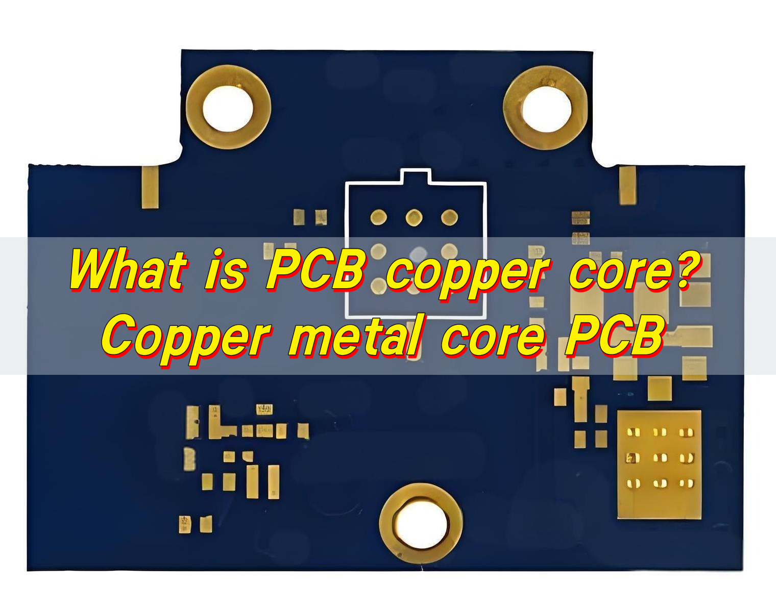
Metal core PCB material is selected when a circuit board needs stronger heat dissipation than a standard FR4 board can provide. Instead of using only fiberglass epoxy as the base, a metal core PCB uses aluminum, copper, or another metal substrate to transfer heat away from components such as LEDs, power ICs, MOSFETs, voltage regulators, motor drivers, and automotive lighting modules.
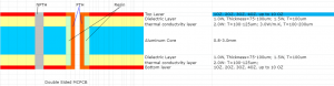
A typical metal core PCB has three key parts: the copper circuit layer, the thermally conductive dielectric layer, and the metal base. The copper layer carries electrical signals and current. The dielectric layer provides insulation while helping heat move downward. The metal base spreads that heat into the housing, heat sink, chassis, or surrounding air.
For many projects, aluminum is the most practical choice. For higher-power or high-current designs, copper may be a better fit. The final choice depends on heat load, current level, board size, insulation requirement, product environment, and cost target.
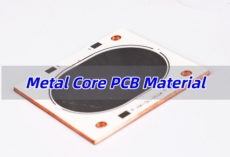
What Is Metal Core PCB Material?
Metal core PCB material refers to the material system used to build a metal core printed circuit board. It is not only the metal base. It also includes the copper foil, insulation layer, solder mask, surface finish, and sometimes special thermal interface materials.
The main purpose of this material system is to move heat away from components more efficiently. In a standard FR4 PCB, heat moves slowly through the fiberglass epoxy base. In a metal core PCB, heat can travel through a thermal dielectric layer into a metal substrate, which spreads heat across a larger area.
A common metal core PCB stack-up includes:
| Layer | Main Function | Why It Matters |
|---|---|---|
| Solder mask | Protects copper traces and prevents solder bridging | Improves surface protection and assembly reliability |
| Copper circuit layer | Carries current and electrical signals | Defines circuit performance and current capacity |
| Thermal dielectric layer | Transfers heat while providing electrical insulation | A key factor in thermal resistance |
| Metal core | Spreads and conducts heat | Usually aluminum or copper |
| Surface finish | Protects exposed copper pads | Supports solderability and assembly quality |
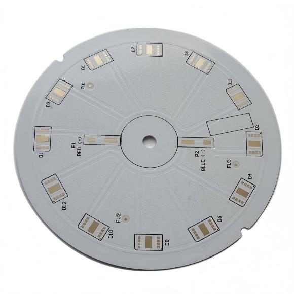
Metal core PCBs are often called MCPCB, IMS PCB or insulated metal substrate PCB. They are widely used in LED lighting, automotive lighting, power electronics, motor control, industrial modules, and thermal management products.
What Materials Are Used in a Metal Core PCB?
The most common materials used in a metal core PCB are aluminum, copper, thermal dielectric material, copper foil, solder mask, and surface finish materials. Each one affects thermal performance, electrical safety, mechanical strength, and manufacturing cost.
Aluminum is the most widely used metal base because it offers a good balance between thermal performance, weight, machinability, and price. Copper provides stronger heat spreading and current-carrying capability, but it is heavier and more expensive. The dielectric layer is especially important because it must conduct heat and insulate electricity at the same time.
| Material | Common Role | Typical Application | Selection Note |
|---|---|---|---|
| Aluminum core | Main heat-spreading base | LED lighting, power supply, automotive lighting | Best balance for cost and thermal performance |
| Copper core | High-performance heat-spreading base | High-power modules, RF, high-current electronics | Better thermal conduction but higher cost |
| Thermal dielectric | Heat transfer and electrical insulation | All metal core PCB structures | A major factor in thermal resistance |
| Copper foil | Electrical circuit layer | Signal and power traces | 1oz, 2oz, 3oz or heavier copper may be used |
| Solder mask | Surface protection | Most assembled PCBs | Must withstand assembly and operating conditions |
| ENIG / HASL / OSP | Surface finish | Solder pads and exposed copper areas | Chosen based on assembly, shelf life, and cost |
Public manufacturing specifications often show dielectric thermal conductivity options around 1W/m·K, 2W/m·K, 3W/m·K, or higher, while metal thickness may range from about 0.4mm to 3.2mm depending on supplier capability and design class.
Why Is Aluminum the Most Common Metal Core PCB Material?
Aluminum is the most common metal core PCB material because it gives designers a practical mix of heat dissipation, light weight, stable mechanical support, and manufacturability. It is widely used when the product needs better thermal control than FR4 but does not require the cost level of copper core PCB.
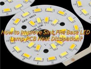
Aluminum core PCB is especially common in LED products. LED chips are sensitive to temperature, and poor heat transfer can reduce luminous efficiency and shorten service life. An aluminum substrate helps move heat from the LED package into the board and then into the fixture body or heat sink.
Aluminum core PCB is also common in:
- LED bulbs and LED modules
- Automotive headlights and taillights
- Street lighting and high-bay lighting
- Power supply boards
- Motor control electronics
- Battery charging products
- Industrial control modules
- Consumer power devices
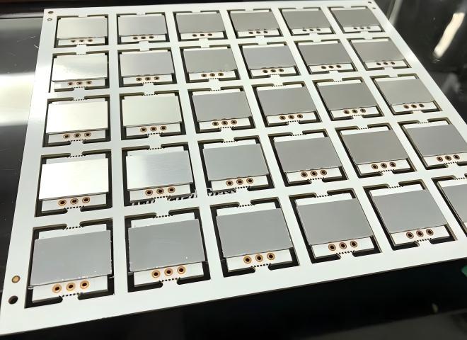
Aluminum PCBs are commonly available in thicknesses such as 1.0mm, 1.5mm, 1.6mm, and 2.0mm, with copper thickness often selected from 1oz to 3oz for many thermal and power designs. Public capability tables from PCB manufacturers show aluminum PCB thickness ranges from about 0.3mm to 3.0mm, with special options available for thicker structures.
Aluminum is not always the highest-performance choice, but it is often the best commercial choice. When the heat load is moderate and the project needs stable quality at a reasonable cost, aluminum core PCB is usually the first material to evaluate.
When Should You Choose Copper Core PCB Material?
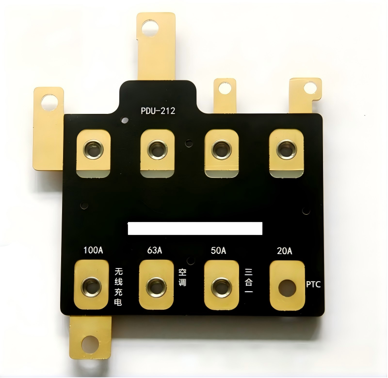
Copper core PCB material should be considered when the design has high heat density, high current, compact board size, or strict reliability requirements. Copper spreads heat faster than aluminum and can support demanding thermal paths in power electronics, RF modules, automotive systems, and aerospace-grade assemblies.
Copper core PCB is suitable for applications such as:
- High-power LED modules
- Power converters and inverters
- High-current control boards
- RF and microwave power modules
- Automotive power electronics
- Aerospace electronics
- Laser diode modules
- High-reliability industrial equipment
The main value of copper core material is its stronger thermal conductivity and current-handling potential. When heat is concentrated in a small area, copper can spread it more quickly across the board. This helps reduce hot spots and improve thermal stability.
However, copper core PCB also requires more careful cost control. Copper is heavier and more expensive than aluminum. It can also be more challenging to machine, drill, and process. For this reason, copper core material is usually selected when the design clearly needs the extra thermal performance.
A good approach is to start with the thermal requirement, not the material name. If aluminum with a high-performance dielectric layer can meet the junction temperature target, it may be the more economical solution. If the design still has heat concentration or current stress, copper core becomes a stronger option.
Is Copper Core Better Than Aluminum Core?
Copper core is better than aluminum core for maximum thermal spreading and high-current applications, but aluminum core is better for many cost-sensitive and weight-sensitive products. The better choice depends on heat load, budget, board size, mechanical structure, and reliability target.
| Comparison Item | Aluminum Core PCB | Copper Core PCB |
|---|---|---|
| Thermal performance | Good | Excellent |
| Weight | Lighter | Heavier |
| Cost | Lower | Higher |
| Machining difficulty | Easier | More difficult |
| Current support | Good for many power designs | Better for high-current structures |
| Common use | LED lighting, power supply, automotive lighting | High-power electronics, RF, aerospace, heavy-current modules |
| Best fit | Balanced thermal and cost requirements | High heat density or high reliability requirements |
For most LED lighting and general power products, aluminum core PCB is enough. For high-power density modules, copper core PCB can be a better investment because it improves heat spreading and reduces thermal stress.
A practical selection rule is simple:
Choose aluminum core when the design needs reliable heat dissipation at a controlled cost. Choose copper core when the product has concentrated heat, high current, limited cooling space, or strict thermal margins.
How Important Is the Dielectric Layer in Metal Core PCB Material?
The dielectric layer is one of the most important parts of metal core PCB material. It sits between the copper circuit and the metal base. Its job is difficult because it must conduct heat while preventing electrical current from reaching the metal core.
Many buyers focus only on whether the board is aluminum or copper. In real thermal design, the dielectric layer can be the bottleneck. Even when the metal base has strong thermal conductivity, heat still needs to pass through the dielectric first.
Important dielectric layer parameters include:
| Parameter | Why It Matters |
|---|---|
| Thermal conductivity | Higher values help heat move through the insulation layer |
| Dielectric thickness | Thinner layers often reduce thermal resistance |
| Breakdown voltage | Ensures electrical insulation safety |
| Peel strength | Helps copper stay bonded to the dielectric |
| Glass transition and thermal stability | Supports soldering and long-term operation |
| Moisture resistance | Helps reliability in humid or outdoor applications |
Typical metal core PCB dielectric materials may offer thermal conductivity from about 1W/m·K to 4W/m·K, with higher grades available from some material systems. Conventional MCPCB structures often rely on the dielectric layer as the main thermal path between copper traces and the metal base.
For LED and power electronics, the dielectric layer should be selected together with component power loss, copper area, board thickness, housing structure, and expected operating temperature. A high-conductivity dielectric may cost more, but it can improve product stability when the heat source is intense.
What Thickness Is Best for Metal Core PCB Material?
The best metal core pcb thickness depends on heat dissipation, mechanical strength, current level, product structure, and assembly requirements. There is no universal thickness that fits every project. Many metal core PCBs use total board thicknesses around 1.0mm, 1.5mm, 1.6mm, or 2.0mm, while special designs may use thinner or thicker structures.
Thickness selection should consider three areas: total board thickness, metal base thickness, and dielectric thickness.
| Thickness Item | Common Range | Selection Guidance |
|---|---|---|
| Total board thickness | 0.8–3.0mm common | Choose based on mechanical support, fixture design, and heat path |
| Aluminum base thickness | 0.5–2.0mm common | Thicker base improves rigidity and heat spreading |
| Copper foil thickness | 1oz–3oz common | Higher current often needs thicker copper |
| Dielectric thickness | 75–150μm common; some specs show wider ranges | Thinner dielectric can improve heat transfer but must meet voltage needs |
| Metal thickness capability | Around 0.4–3.2mm in some public specifications | Depends on manufacturer capability and stack-up |
Some public MCPCB manufacturing data lists metal thickness around 0.4–3.2mm and dielectric thickness around 100–300μm, depending on standard or advanced capability.
For LED boards, 1.5mm or 1.6mm aluminum core PCB is commonly selected because it offers good mechanical stability and familiar assembly handling. For automotive lighting or higher-power designs, thicker metal bases may be used to increase heat spreading and structural strength.
When selecting thickness, avoid looking at only the total board number. A 1.6mm metal core PCB can behave very differently depending on copper thickness, dielectric thickness, dielectric thermal conductivity, and base metal type.
Metal Core PCB vs FR4: Which Is Better for Heat Dissipation?
Metal core pcb vs fr4 is mainly a heat dissipation comparison. Metal core PCB is better for heat dissipation because its aluminum or copper substrate spreads heat faster than fiberglass epoxy. FR4 is still suitable for general electronic products, signal circuits, control boards, and multilayer routing, but it is not the first choice for high-power thermal designs.
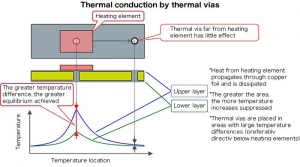
FR4 is widely used because it is cost-effective, easy to process, and suitable for multilayer circuits. However, when components generate significant heat, FR4 often needs extra thermal vias, copper pours, heat sinks, or larger board area. Metal core PCB creates a more direct heat path from the component to the metal base.
| Feature | FR4 PCB | Metal Core PCB |
|---|---|---|
| Base material | Fiberglass epoxy laminate | Aluminum, copper, or metal alloy |
| Thermal performance | Limited | Strong |
| Typical thermal conductivity | Around 0.3W/m·K for many FR4 materials | Often much higher through thermal dielectric systems |
| Best use | General electronics, control circuits, multilayer designs | LEDs, power modules, thermal products |
| Layer complexity | Very flexible for multilayer routing | More limited, especially in simple MCPCB structures |
| Mechanical rigidity | Good | Very strong |
| Cost | Usually lower | Usually higher |
| Heat sink integration | Often needs extra design work | Easier to connect to housing or heat sink |
FR4 thermal conductivity is often cited around 0.25–0.3W/m·K, while MCPCB dielectric systems are commonly listed around 1–4W/m·K or higher depending on material grade.
Choose FR4 when the circuit is low-power, routing density is high, or cost control is the main goal. Choose metal core PCB when heat is a primary design concern, especially for LEDs, power devices, automotive lighting, and compact electronics with limited cooling space.
How to Choose the Right Metal Core PCB Material for Your Design?
To choose the right metal core PCB material, start with the heat source and working environment. Then match the metal base, dielectric layer, copper thickness, surface finish, and board thickness to the actual product requirement.
A clear selection process helps reduce redesign risk:
1. Identify the heat source
List the components that generate heat, such as LEDs, MOSFETs, power ICs, regulators, bridge rectifiers, or high-current connectors.
2. Estimate power loss
Check how much heat the component will generate during normal and peak operation. Use this to define the thermal path.
3. Choose aluminum or copper core
Use aluminum for most balanced thermal designs. Use copper when heat density or current level is high.
4. Select dielectric thermal conductivity
For general LED and power designs, 1–2W/m·K may be enough. For compact or high-power designs, 3W/m·K or higher may be considered.
5. Check dielectric thickness and voltage requirement
A thinner dielectric can improve heat transfer, but it must still meet insulation and breakdown voltage requirements.
6. Define copper thickness
For low-to-medium current circuits, 1oz copper may be enough. For power boards, 2oz or 3oz copper is often considered.
7. Confirm total metal core pcb thickness
Match the board thickness with mechanical mounting, housing flatness, screw holes, thermal interface material, and assembly process.
8. Review surface finish
ENIG, HASL, lead-free HASL, and OSP may be selected depending on assembly, shelf life, solderability, and cost.
9. Discuss DFM before production
Before mass production, the stack-up, hole design, outline tolerance, solder mask clearance, copper spacing, thermal pad design, and assembly method should be reviewed.
A strong MCPCB design is not built by choosing the most expensive material. It is built by matching the right material to the real thermal path.
Why Choose EBest Circuit as Your Metal Core PCB Manufacturer?
Choosing the right metal core pcb manufacturer is important because MCPCB quality depends on material selection, lamination control, dielectric reliability, copper bonding, surface finish, machining accuracy, and thermal performance. A small stack-up mistake can affect heat transfer, soldering, assembly, and long-term stability.
EBest Circuit supports metal core PCB projects from early design review to fabrication, assembly, and testing. For customers developing LED lighting, automotive electronics, industrial controls, power modules, medical electronics, communication products, and UAV systems, EBest can help review the material stack-up before production.
EBest Circuit can support:
- Aluminum core PCB manufacturing
- Copper core PCB manufacturing
- DFM review before fabrication
- Thermal material and stack-up suggestions
- Prototype and small-batch production
- PCB fabrication and PCBA assembly
- Component sourcing and BOM support
- AOI, X-ray, electrical testing, and process inspection
- Quality control for regulated and high-reliability applications
For customers who are not sure whether to use aluminum core, copper core, or FR4, EBest can review the drawing, Gerber file, BOM, current load, heat source, and application environment. This helps avoid over-design and under-design.
A reliable metal core PCB manufacturer should not only produce the board. It should help customers make practical decisions about thermal conductivity, dielectric thickness, copper weight, surface finish, and assembly risk.
FAQs
1. What is metal core PCB material?
Metal core PCB material is the material system used in a metal core printed circuit board. It usually includes a copper circuit layer, thermal dielectric layer, and aluminum or copper metal base. Its main purpose is to improve heat dissipation.
2. What is the most common metal core PCB material?
Aluminum is the most common metal core PCB material. It offers a good balance of thermal performance, weight, cost, and manufacturability, making it suitable for LED lighting, power supplies, automotive lighting, and industrial electronics.
3. Is copper core better than aluminum core?
Copper core is better for high thermal conductivity and high-current designs. Aluminum core is better for many projects that need reliable heat dissipation at a more controlled cost. The better choice depends on heat load, budget, and application.
4. What is the normal metal core pcb thickness?
Common metal core pcb thickness options include 1.0mm, 1.5mm, 1.6mm, and 2.0mm. Some projects may use thinner or thicker boards depending on heat dissipation, mechanical structure, and assembly requirements.
5. Is metal core PCB better than FR4?
Metal core PCB is better than FR4 for heat dissipation. FR4 is better for general electronics, complex multilayer routing, and cost-sensitive low-power circuits. For LEDs, power modules, and automotive lighting, metal core PCB is often the better thermal choice.
6. What is the dielectric layer in metal core PCB material?
The dielectric layer is the insulating layer between the copper circuit and the metal base. It transfers heat while preventing electrical current from reaching the metal core. Its thermal conductivity and thickness strongly affect board performance.
7. Can metal core PCB be multilayer?
Yes, metal core PCB can be designed as single-layer, double-layer, or more complex structures. However, multilayer MCPCB requires careful stack-up design, insulation control, drilling process, and manufacturer review.
8. How do I choose a metal core PCB manufacturer?
Choose a metal core PCB manufacturer with material knowledge, DFM support, stable fabrication capability, thermal stack-up experience, testing systems, and PCB assembly support. For high-power or high-reliability products, early engineering review is especially valuable.
Conclusion
Need support with metal core PCB material selection or MCPCB manufacturing? Contact EBest Circuit for DFM review, material suggestions, PCB fabrication, PCBA assembly, and prototype-to-production support.