PCB manufacturing PCB manufacturing
Home > Blog

metal core circuit board

Best Metal Core Circuit Board Manufacturer in China | Thermal Solution
Wednesday, May 6th, 2026

Are you struggling with overheating, signal instability, low yield, or long lead time in your metal core circuit board projects? This guide breaks down real-world pain points in design, prototyping, and assembly, shares proven solutions, and shows how EBest delivers reliable, high-performance metal core circuit board and metal core printed circuit board solutions for LED, medical, aerospace, and industrial applications. We combine 20+ years of expertise, strict certifications, and one-stop services to solve your thermal and reliability challenges.

Metal Core Circuit Board, https://www.bestpcbs.com/blog/2026/05/metal-core-circuit-board-2/

What Are the Pain Points in Metal Core Circuit Board Design and How Do We Solve Them?

Metal core circuit board design often brings thermal, electrical, and manufacturability conflicts. Below we list the most common pain points and our targeted engineering fixes.

  • Poor thermal conductivity causing overheating in high‑power devices: We optimize dielectric layer thickness and metal substrate selection to boost heat dissipation.
  • Signal interference and crosstalk in dense layouts: We use grounded metal cores and impedance matching to stabilize signal integrity.
  • Complex DFM rules leading to low yield: Our engineers provide early design reviews and standardized design guidelines.
  • Warpage and deformation under thermal cycles: We balance material CTE and apply structural reinforcement in layout.
  • Insulation breakdown risk at high voltage: We use high‑quality dielectric materials and strict creepage/clearance control.
  • Difficulty integrating HDI structures: We combine laser drilling and metal core processing for reliable HDI integration.

What Are the Challenges in Metal Core Circuit Board Prototype and How Do We Fix Them?

Prototyping metal core printed circuit boards often means tight deadlines, inconsistent quality, and high costs. Here’s how we eliminate those hurdles.

  • Long lead times delaying product development: We offer 24-hour rapid prototyping for urgent metal core circuit board projects.
  • Inconsistent performance between prototype and mass production: We use stable production lines and unified materials for prototypes.
  • High cost for small‑batch prototypes: We provide flexible MOQ and cost‑effective prototype solutions.
  • Poor dimensional accuracy in complex structures: We apply precision machining and online inspection throughout production.
  • Material compatibility failures: We pre‑test metal substrates, dielectrics, and copper foils for reliability.
  • Limited prototype customization: We support single‑sided, double‑sided, and multilayer custom prototypes.

What Are the Problems in Metal Core Circuit Board Assembly and How Do We Solve Them?

Assembly of metal core printed circuit boards involves unique thermal and mechanical stresses. We address every common failure point to ensure robust, long‑lasting assemblies.

  • Component damage from excessive heat during soldering: We use controlled reflow profiles and thermal buffer designs.
  • Poor solder wetting on metal core boards: We optimize surface finishes and pre‑treat metal substrates.
  • Thermal stress causing delamination or cracking: We match CTE and reinforce key assembly areas.
  • Difficulty with thick or heavy boards: We provide rigid support fixtures and professional assembly lines.
  • Insulation defects after assembly: We perform 100% electrical and hi‑pot testing.
  • Low efficiency in mixed assembly: We integrate SMT, through‑hole, and connector assembly in one stop.

Why Choose EBest as Your Metal Core Circuit Board Manufacturer in China?

EBest focuses on services that directly improve your product performance, speed, and reliability. We deliver end-to-end support for your metal core circuit board needs.

  • Professional metal core circuit board design review & DFM optimization: Our experienced engineers conduct comprehensive design audits to identify potential manufacturability issues (such as acid traps or weak annular rings) in advance,lowering production failure rates, reducing rework costs, and ensuring your project stays on budget and on schedule.
  • Rapid 24-hour prototyping for metal core printed circuit boards: We prioritize your R&D timeline with urgent prototyping services, speeding up your product development cycle, helping you test and validate designs faster, and gaining a competitive edge in the market.
  • Full-process assembly (SMT + through-hole + testing) for one-stop project delivery: We integrate all assembly processes in-house, eliminating handovers between multiple factories, shortening lead times, reducing quality variation risks, and saving you time and effort in coordinating multiple suppliers.
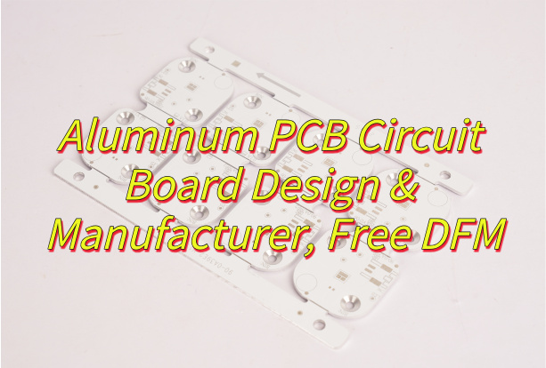
  • Custom material matching (aluminum/copper/alloy) for ideal thermal performance: We tailor substrate material selection to your specific project needs, ensuring optimal heat dissipation, improving the stability and lifespan of your end products, and avoiding overheating-related failures.
  • Strict quality control with IATF 16949, ISO 9001, ISO 13485, AS9100D, RoHS, REACH, UL: Our certified quality management system covers every production step, guaranteeing consistent product quality, ensuring compliance with global industry standards, and giving you confidence in using our products in regulated industries like medical, aerospace, and automotive.
  • Stable mass production with consistent quality from prototype to volume: We maintain unified production processes and material standards for both prototypes and mass production, ensuring no performance differences between small-batch samples and large-volume orders, stabilizing your per-unit costs, and supporting your long-term production planning.
  • Thermal simulation & reliability testing to validate performance before shipment: We conduct rigorous thermal and reliability tests prior to delivery, identifying potential performance issues in advance, ensuring your metal core circuit boards meet design expectations, and reducing post-delivery maintenance costs.
  • Flexible order quantities from samples to mass production: We support small-batch samples, medium-volume orders, and large-scale mass production, accommodating your project’s different stages, reducing your initial investment risk, and scaling seamlessly with your business growth.
  • 24/7 technical support from layout to after-sales: Our professional technical team is available around the clock, providing timely guidance from design layout to after-sales use, solving your technical problems quickly, and ensuring your project progresses smoothly without delays.

What Types of Metal Core Printed Circuit Boards Can EBest Provide?

We support standard and custom configurations to match your thermal, electrical, and mechanical needs.

  • Single sided metal core printed circuit board
  • Double sided metal core printed circuit board
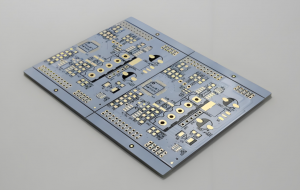
  • Customized multilayer metal core circuit boards PCB
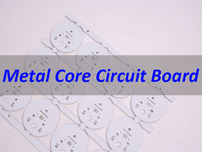
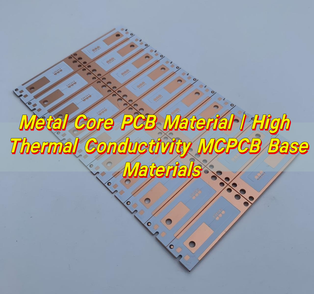
  • High thermal conductivity metal core printed circuit boards
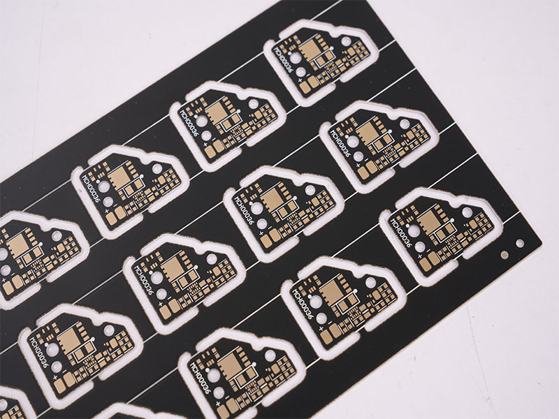
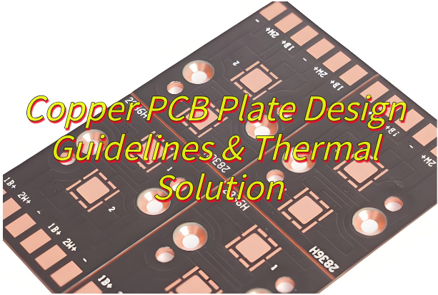
  • Heavy copper metal core printed circuit board
  • High‑TG metal core printed circuit boards
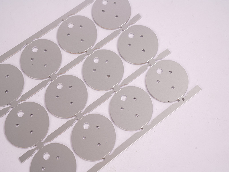
  • Thin metal core printed circuit board for compact devices
metal core circuit board, https://www.bestpcbs.com/blog/2026/05/metal-core-circuit-board-2/

What Qualifications Should a Reliable Metal Core Circuit Board Manufacturer Have?

A trusted provider must meet industry, quality, and technical benchmarks to ensure safe, consistent metal core circuit board production.

  • ISO 9001 quality management system
  • IATF 16949 for automotive, ISO 13485 for medical, AS9100D for aerospace
  • RoHS and REACH compliance for environmental safety
  • UL safety certification for global markets

How Does EBest Ensure Superior Thermal Conductivity in Metal Core Circuit Boards?

We use a full-system, engineering-driven approach to maximize heat dissipation in every metal core circuit board, addressing material selection, design, production, and testing to ensure superior thermal conductivity. Below are our key steps, detailed yet concise:

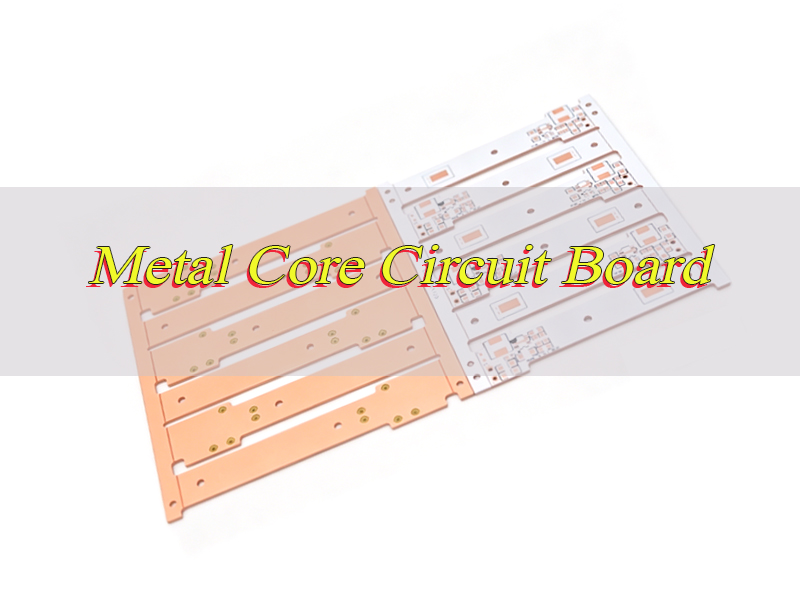
  • Customized Metal Substrate Selection: We select high-purity aluminum, copper, or alloy substrates based on your specific thermal demand. Aluminum substrates (150–240 W/mK) offer cost-effective thermal performance for most applications, while copper substrates (385–400 W/mK) deliver maximum heat dissipation for ultra-high-power scenarios, ensuring optimal heat transfer from components to the heat sink.
  • High-K Dielectric Layer Optimization: We use high-k dielectric materials (k value 6–100+) with thermal conductivity of 3.0–8.0 W/(m・K) — far superior to standard FR-4 (0.3–0.4 W/mK) to balance low thermal resistance and high insulation. This ensures efficient heat transfer while preventing electrical breakdown[superscript:2].
  • Precise Dielectric Thickness Control: We precisely adjust dielectric layer thickness (typically 50–200 μm) to strike the perfect balance between heat transfer and voltage safety. Thinner layers reduce thermal resistance, while ensuring adequate breakdown voltage to meet your project’s electrical requirements.
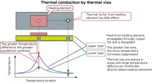
  • High-Density Thermal Via Design: We deploy high-density thermal via arrays with thermally conductive resin plugging to eliminate heat accumulation points. These vias create direct heat paths from components to the metal core, minimizing thermal bottlenecks and ensuring uniform heat distribution across the board.
  • Thermal Simulation & Layout Optimization: Before production, we use thermal simulation tools to optimize component placement and heat dissipation paths. We position high-power components over metal core areas and avoid heat coupling, ensuring efficient heat spread and preventing hotspots that degrade performance.
  • Void-Free Vacuum Lamination: We use stable vacuum lamination with controlled pressure to eliminate microscopic air gaps (which act as thermal insulators). This ensures consistent bonding between layers, minimizing interface thermal resistance and maximizing heat transfer efficiency.
  • 100% Pre-Shipment Thermal & Electrical Testing: Every metal core circuit board undergoes rigorous thermal conductivity and electrical tests before shipment. We verify thermal performance meets design specifications, ensuring no defects and guaranteeing consistent, reliable heat dissipation for your end products.
metal core circuit board, https://www.bestpcbs.com/blog/2026/05/metal-core-circuit-board-2/

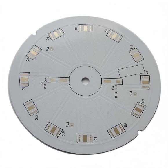
EBest’s Metal Core Circuit Board for LED Lighting Industry Case Study

This real-world case demonstrates how our metal core circuit board solutions address core pain points of high-power LED lighting, delivering tangible value for our clients. We focus on practical, results-driven solutions tailored to LED lighting industry needs.

Project Background

Our client, a global LED lighting manufacturer, had critical issues with their high-power LED streetlights: severe heat buildup in the closed lamp housing caused rapid lumen decay (30% within 6 months), frequent dead lights, and a shortened service life (under 20,000 hours), damaging their reputation and increasing after-sales costs.

Project Requirements

The client’s core needs centered on resolving heat-related failures and ensuring market competitiveness, with clear, measurable goals:

  • Resolve heat dissipation issues to ensure stable long-term operation of LED streetlights.
  • Extend the LED streetlight service life to over 50,000 hours (a standard benchmark for high-quality LED lighting).
  • Reduce lumen decay to less than 10% within 2 years (far below the industry average for poorly cooled products).
  • Completely eliminate dead light problems caused by overheating.
  • Maintain compliance with RoHS and UL standards to ensure global market access.

Our Solution

We customized a high-thermal metal core printed circuit board specifically tailored to their LED streetlight specifications, addressing every heat dissipation pain point with targeted engineering:

  • Substrate selection: Chose high-purity 1060 aluminum substrates (with excellent thermal conductivity of 205W/(m・K)) to accelerate heat transfer from LED chips to the heat sink.
  • Dielectric layer optimization: Set dielectric layer thickness to 0.15mm and used high-k dielectric materials (thermal conductivity 3.0-4.0W/(m・K)) to balance heat dissipation and insulation performance, reducing thermal resistance by 50% compared to standard materials.
  • Thermal via design: Added high-density thermal via arrays with resin plugging to eliminate heat accumulation points, ensuring uniform heat distribution across the board.
  • Layout & validation: Optimized the board layout to avoid heat coupling between components, conducted pre-production thermal simulations to verify design effectiveness, and provided 24-hour rapid prototyping for quick validation of performance.

Project Results

After mass production and on-site testing, the LED streetlights equipped with our metal core printed circuit boards delivered tangible, measurable improvements for the client:

  • Temperature control: Stable operating temperatures reduced by 25℃ compared to the client’s previous solution, keeping LED chip junction temperature below 70℃ (the threshold for avoiding accelerated lumen decay).
  • Lumen decay & lifespan: Lumen decay was controlled within 8% after 2 years of continuous operation, and service life extended to 55,000 hours (exceeding the client’s 50,000-hour requirement).
  • Reliability improvement: Dead light issues were completely eliminated, reducing the client’s after-sales maintenance costs by 40%.
  • Market compliance: The product fully met RoHS and UL standards, helping the client expand their global market share and enhance brand credibility.

What Should You Look for When Choosing a Metal Core Circuit Board Manufacturer?

Focus on these critical factors to select a partner that delivers consistent, high‑quality metal core circuit board solutions.

  • Strong thermal design and testing capabilities: Prioritize manufacturers with professional thermal design teams and advanced testing equipment. They should offer thermal simulation services to optimize metal core circuit board layout and heat dissipation paths, and have in-house labs to conduct thermal conductivity, thermal cycling, and insulation tests, this ensures the board meets your heat management needs and avoids overheating-related failures.
  • Complete industry certifications matching your target market: Certifications are non-negotiable for reliability and market access. Ensure the manufacturer holds ISO 9001 (basic quality), plus industry-specific certifications: IATF 16949 (automotive), ISO 13485 (medical), AS9100D (aerospace), as well as RoHS, REACH, and UL compliance to meet global regulatory requirements.
  • One-stop service covering design, prototyping, assembly, and mass production: Choose a manufacturer that offers end-to-end services to avoid coordination hassle between multiple suppliers. This includes DFM design reviews, rapid prototyping, SMT/through-hole assembly, and mass production, which shortens lead times, reduces quality inconsistencies, and saves you time and costs.
  • Consistent quality between prototype and mass production: Inconsistent performance between samples and bulk orders is a common pain point. Verify the manufacturer uses unified materials, production processes, and quality control standards for both prototypes and mass production to ensure stable product performance and avoid rework or product failures post-launch.
  • Flexible customization for special requirements: Your metal core circuit board may need custom specifications (e.g., single/double/multilayer structures, heavy copper, thin boards, or high-TG materials). The manufacturer should accommodate custom material selection, layer designs, and dimensional requirements to match your specific product needs.
  • Fast, reliable lead times and urgent order support: Timely delivery is critical for your R&D and production schedules. Look for manufacturers that offer 24-hour rapid prototyping for urgent projects and have stable production capacity to meet your mass production deadlines, even during peak periods.
  • Transparent quality control (QC) processes and test reports: A reliable manufacturer will have transparent QC processes covering every production step from material inspection to final shipment. They should provide detailed test reports (thermal, electrical, reliability) to prove product quality, giving you confidence in the boards you receive.
  • Experienced engineering and after-sales support: Optimize for a manufacturer with a professional engineering team that can provide timely guidance from design layout to problem-solving. 24/7 after-sales support is also essential to resolve any issues (e.g., performance discrepancies) quickly and avoid project delays.
Metal Core Circuit Board, https://www.bestpcbs.com/blog/2026/05/metal-core-circuit-board-2/

FAQs About Metal Core Circuit Board

Q1: What is the current trend in the metal core printed circuit board market? A1: The metal core printed circuit board market is growing rapidly, driven by LED, automotive, industrial, and 5G applications. Demand is rising for higher thermal conductivity, thinner structures, heavy copper, and multilayer designs.

Q2: What factors affect metal core printed circuit board performance? A2: Key factors include metal substrate type, dielectric material, layer structure, thermal design, production process, and assembly quality.

Q3: What is the difference between aluminum and copper metal core printed circuit boards? A3: Aluminum offers good thermal performance at a lower cost; copper provides higher thermal conductivity for ultra‑high‑power applications.

Q4: Can metal core printed circuit boards be used in high‑frequency devices? A4: Yes, with optimized dielectric and layout, metal core circuit board supports high‑frequency and RF applications.

Q5: Are metal core printed circuit boards suitable for mass production? A5: Yes, EBest provides stable mass production for metal core printed circuit boards with consistent quality.

Q6: How to improve thermal performance of a metal core printed circuit board? A6: Optimize substrate material, dielectric layer, thermal vias, component layout, and heat sink design.

Q7: What industries use metal core printed circuit boards most? A7: LED lighting, automotive electronics, industrial power, medical devices, aerospace, and 5G communications.

Contact EBest for Your Metal Core Circuit Board Needs

EBest is a leading metal core circuit board manufacturer in China, providing professional custom thermal solutions. We support design, prototyping, assembly, and mass production for global clients. For inquiries about metal core printed circuit boards, please contact us at: sales@bestpcbs.com.

You may also like

Metal Core Circuit Board Manufacturer | From Prototype to Mass Production
Wednesday, April 22nd, 2026

A metal core circuit board (MCPCB) is a specialized printed circuit board designed to solve one critical issue in modern electronics—heat. By replacing traditional FR4 with a thermally conductive metal base, MCPCBs significantly improve heat dissipation, making them essential for high-power and high-reliability applications.

Common Challenges in High-Power PCB Design

  • Component Overheating
    High-power components generate excessive heat, reducing efficiency and lifespan.
  • Thermal Fatigue Failures
    Repeated heating cycles weaken solder joints and increase failure rates.
  • Limited Power Density
    FR4 materials restrict compact, high-power layouts.
  • High Cooling Cost
    External heat sinks and fans increase BOM and assembly complexity.
  • Supplier Instability
    Difficulty finding a reliable partner for both prototyping and volume production.

Our Tailored MCPCB Solutions

  • Efficient Heat Dissipation
    Heat transfers directly through the metal base, improving thermal performance.
  • Extended Product Lifespan
    Lower operating temperatures reduce stress and improve reliability.
  • Compact Design Support
    Higher power density enables smaller and lighter products.
  • Reduced System Cost
    Integrated thermal design reduces need for external cooling.
  • One-Stop Manufacturing
    From prototype to mass production with stable quality and pricing.

EBest Circuit is a professional metal core printed circuit board manufacturer specializing in high-performance thermal solutions. We support applications from LED lighting to telecom and automotive systems. Our strength lies in combining material expertise with strict process control. Whether you need a single double sided metal core printed circuit board prototype or large-scale production, we ensure consistent thermal and electrical performance. For fast quotation and engineering support, pls feel free to contact us via sales@bestpcbs.com.

Metal Core Circuit Board

What Is a Metal Core Circuit Board?

A metal core circuit board replaces the standard FR4 substrate with a metal base, typically aluminum or copper. This metal layer acts as a heat spreader, allowing heat to move away from critical components efficiently.

The typical MCPCB structure includes:

  • Circuit Layer – Copper traces for electrical connection
  • Dielectric Layer – Thermally conductive insulation
  • Metal Core – Heat dissipation base

In practice, MCPCB integrates heat management directly into the PCB itself, making it ideal for high-power electronic designs.

Why Choose MCPCB Over FR4?

The key difference lies in thermal performance. FR4 is cost-effective but thermally inefficient, while MCPCB is designed specifically for heat management.

MCPCB vs FR4 Comparison

FeatureFR4 PCBMetal Core PCBDesign Impact
Thermal Conductivity~0.3 W/mK1–8+ W/mK3x–25x better heat transfer
Heat DissipationPoorExcellentLess external cooling needed
Mechanical StrengthGoodHighBetter durability
CostLowHigherUsed in high-power designs
ApplicationsGeneral electronicsLED, power, automotiveThermal-critical systems

As a result, MCPCB is the preferred choice when heat directly impacts performance and reliability.

What Materials Are Used in MCPCB?

The performance of a metal core printed circuit board depends on three key materials:

1. Metal Core

  • Aluminum – Most common, cost-effective, good thermal performance
  • Copper – Best thermal conductivity, higher cost
  • Steel – Used for structural or shielding needs

2. Dielectric Layer

  • Provides electrical insulation
  • Transfers heat to metal core
  • Typical conductivity: 1.0–8.0 W/mK

3. Copper Layer

  • Forms electrical circuits
  • Thickness varies based on current requirements

From a design perspective, selecting the right material combination directly determines thermal efficiency and reliability.

Types of Metal Core Circuit Boards

TypeStructureKey BenefitTypical Use
Single-SidedOne copper layerLow cost, high efficiencyLED modules
Double-SidedTwo copper layersMore routing flexibilityPower circuits
MultilayerMultiple layersHigh density designRF, aerospace
Flexible MCPCBBendable structureSpace savingWearables

In real applications, the choice depends on circuit complexity, thermal requirements, and budget.

How MCPCB Improves Thermal Management

MCPCB improves thermal performance by creating a direct heat path:

  • Heat flows from component to copper layer
  • Passes through dielectric layer
  • Transfers into metal core
  • Spreads across board surface

This significantly reduces thermal resistance and prevents hot spots.

For engineers, this means higher power handling, better reliability, and more compact designs.

Typical Applications of MCPCB

MCPCBs are widely used in heat-intensive applications:

  • LED Lighting – street lights, automotive headlights
  • Power Electronics – converters, motor drivers
  • Automotive Systems – ECU, battery modules
  • Telecom & RF – power amplifiers, transmitters
  • Industrial Equipment – inverters, control systems

In high-power scenarios, MCPCB is often the only practical solution to manage heat effectively.

How to Choose the Right Manufacturer

Selecting a reliable metal core circuit board manufacturer is critical.

Key Evaluation Points:

  • Material Expertise – aluminum, copper, dielectric selection
  • Process Capability – multilayer, heavy copper, thermal vias
  • Prototype to Volume – seamless scaling
  • Engineering Support – DFM and thermal design advice
  • Certifications – ISO, automotive standards

This means your supplier should not just produce boards, but also optimize your thermal design.

Top Metal Core PCB Manufacturers in China

ManufacturerStrengthBest For
EBest CircuitLarge-scale productionHigh volume
FastprintAdvanced PCB techHDI & IC
Sihui FujiLED specializationLighting
JLCPCBLow-cost prototypeStartups
PCBCartEngineering supportCustom design
KinwongThermal expertiseHigh-reliability MCPCB

In practice, the best choice depends on your project scale, complexity, and support needs.

What Affects MCPCB Cost?

Key cost drivers include:

  • Material Type – copper vs aluminum
  • Thermal Conductivity – higher = higher cost
  • Layer Count – multilayer increases complexity
  • Copper Thickness – heavy copper adds cost
  • Board Size & Shape – affects material usage
  • Order Volume – larger quantity reduces unit price

As a result, optimizing design early can significantly reduce total cost.

In short, a metal core circuit board is not just a PCB—it is a thermal solution. By integrating heat dissipation into the board itself, MCPCBs enable higher performance, longer lifespan, and more compact designs.

For projects that demand reliable thermal management, choosing the right partner is essential. EBest Circuit provides full support from prototype to mass production, ensuring your design meets both electrical and thermal requirements. Pls kindly note that free DFM and thermal design support available. A warm welcome to get a fast quote within 24 hours via sales@bestpcbs.com.

Technical FAQs About Metal Core Circuit Board

1. Why Is an Aluminum PCB More Reliable Than FR4 for LED Surgical Lights?

Aluminum PCBs are better suited for surgical lighting because their high thermal conductivity helps prevent lumen depreciation and color shifting during critical procedures. Unlike FR4, which tends to trap heat, an aluminum substrate quickly transfers thermal energy away from the LED dies. This helps maintain a stable junction temperature, so light output remains consistent and the color rendering index (CRI) stays reliable. For medical lighting, that level of stability is essential.

2. What Are the Primary Cost Drivers in MCPCB Manufacturing?

The cost of a metal core PCB is mainly influenced by the thermal conductivity of the dielectric layer and the choice of base material.

  • Thermal conductivity of the dielectric layer:
    High-performance dielectric materials, such as 3.0 W/mK and above, are usually much more expensive than standard 1.0 W/mK options.
  • Base material selection:
    Copper substrates provide stronger thermal performance, but they are much more expensive and heavier than aluminum substrates.
  • Secondary processing requirements:
    Extra processes such as ENIG surface finish, heavy copper foil, or complex mechanical routing for custom housings will also increase the total cost.

3. How Is Dielectric Breakdown Prevented in High-Voltage MCPCB Designs?

Dielectric breakdown is prevented by selecting an insulating layer with sufficient dielectric strength to handle the maximum operating voltage of the application. In power electronics and automotive systems, the insulation layer between the copper circuit and the metal base must provide stable electrical isolation. High-quality MCPCBs are often designed to pass Hi-Pot testing from 2000 VAC to 6000 VAC, depending on the dielectric thickness and material composition.

4. How Do Metal Core PCBs Perform in Extreme Outdoor Environments?

Metal core PCBs perform very well in harsh outdoor environments because they offer strong mechanical stability and excellent resistance to thermal shock. In applications such as street lights and construction warning lights, the metal base helps prevent warping during repeated temperature changes. At the same time, the rigid aluminum or copper core protects solder joints from cracking under vibration or physical impact, which is a common issue with traditional FR4 boards used outdoors.

You may also like

Metal Core PCB Material | High Thermal Conductivity MCPCB Base Materials
Friday, March 6th, 2026

Electronic devices continue to shrink while power density keeps rising. Excess heat can shorten component life, reduce performance, and cause signal instability. Because of this, designers often select metal core PCB material instead of conventional laminates when thermal control becomes critical.

A metal core circuit board integrates a thermally conductive metal base beneath the dielectric and copper circuitry. This structure creates a direct path for heat to travel away from components. Compared with standard FR-4 boards, metal core PCBs can dissipate heat more efficiently and maintain better thermal balance during operation.

Metal Core PCB Material | High Thermal Conductivity MCPCB Base Materials

These boards are widely used in high-power LED lighting, automotive electronics, power converters, industrial control systems, and communication equipment. As power levels increase and device footprints shrink, engineers increasingly rely on aluminium core PCB, copper core PCB, and IMS PCB (Insulated Metal Substrate) technologies to stabilize thermal performance.

EBest Circuit (Best Technology)’s metal core PCB material provides excellent thermal conductivity, high stability and reliable performance for LED, power and high‑heat electronic applications.

What materials are used in metal core PCB?

A typical metal core PCB material structure consists of three primary layers. These layers work together to transfer heat efficiently from components to the metal substrate. Each layer performs a specific thermal and electrical function that ensures stable circuit performance.

The typical MCPCB stack structure includes:

  • Copper circuit layer
  • Thermal dielectric layer
  • Metal base layer

1. Copper Circuit Layer

The top layer contains copper traces that form the electrical circuit. This layer functions similarly to the copper layer in standard PCBs. Thicker copper improves current carrying capability and also spreads heat across the board surface. Copper thickness usually ranges from:

Copper ThicknessTypical Use
1 oz (35 μm)Standard LED and low-power circuits
2 oz (70 μm)Power LED modules
3 oz – 4 ozHigh-current power electronics

2. Thermal Dielectric Layer

The dielectric layer is a critical part of metal core PCB material. It electrically isolates the circuit from the metal base while still allowing heat to pass through. High thermal conductivity dielectric materials allow heat to move quickly from components into the metal base. Typical dielectric properties include:

PropertyTypical Range
Thermal conductivity1 W/mK – 10 W/mK
Thickness50 μm – 150 μm
Breakdown voltage2 kV – 6 kV

Common dielectric fillers include:

  • Ceramic particles
  • Aluminum oxide
  • Silicon compounds

These fillers increase thermal conductivity while maintaining insulation strength.

3. Metal Base Layer

The bottom layer of a pcb metal core acts as the primary heat sink. It spreads heat over a large surface area and transfers it to the external environment. Aluminum is widely used because it provides strong thermal performance at a reasonable cost. Copper offers the highest thermal conductivity but is heavier and more expensive. The most common base materials are:

Metal Base TypeThermal Conductivity
Aluminum~200 W/mK
Copper~385 W/mK
Steel~50 W/mK

How to choose metal core PCB material?

Selecting the right metal core pcb material depends on several engineering factors. The design must balance thermal performance, mechanical strength, electrical insulation, and manufacturing cost.

1. Thermal conductivity requirement

Heat dissipation is the main reason for using IMS PCB technology. The thermal conductivity of the dielectric layer determines how quickly heat moves into the metal base. Higher conductivity improves cooling performance. Typical ranges include:

Thermal ConductivityApplication
1–2 W/mKStandard LED lighting
3–5 W/mKAutomotive lighting
5–10 W/mKHigh-power electronics

2. Electrical insulation performance

Although the metal base conducts heat well, it must remain electrically isolated from the circuit layer. Reliable insulation prevents short circuits and protects sensitive components. Designers must verify:

  • Dielectric breakdown voltage
  • Insulation resistance
  • Long-term reliability under temperature cycling

3. Mechanical stability

Mechanical strength is also important when selecting metal core PCB materials. Aluminum substrates provide good rigidity while keeping board weight low. Copper base boards offer superior strength but increase overall board mass.

4. Manufacturing compatibility

Manufacturers evaluate whether the material supports standard processes such as:

  • SMT assembly
  • reflow soldering
  • drilling and routing
  • surface finishing

A stable material simplifies production and improves yield.

Metal Core PCB Material | High Thermal Conductivity MCPCB Base Materials

What material is the MCPCB made of?

An MCPCB (Metal Core Printed Circuit Board) typically combines three major materials: copper circuitry, thermal dielectric, and a metal substrate. However, within this structure, several variants exist depending on the application.

Aluminum Core PCB

An aluminium core PCB is the most widely used type of MCPCB. Aluminum offers excellent thermal conductivity while remaining lightweight and cost-effective. Typical aluminum grades used include:

  • 5052 aluminum
  • 6061 aluminum
  • 1060 aluminum

Advantages of aluminum core PCB include:

  • Lightweight structure
  • Good heat dissipation
  • Low material cost
  • Stable mechanical properties

Because of these benefits, aluminum core boards dominate LED lighting and power modules.

Copper Core PCB

A copper core PCB uses a solid copper substrate instead of aluminum. Copper has almost double the thermal conductivity of aluminum. This allows heat to move even faster away from components. However, copper boards are heavier and more expensive. Copper core PCBs are often used in:

  • high-power LEDs
  • RF power amplifiers
  • motor drivers
  • automotive electronics

IMS PCB (Insulated Metal Substrate)

An IMS PCB refers to a board where a dielectric layer isolates the circuit from the metal base. Most metal core PCBs fall into this category. The IMS structure allows designers to combine electrical insulation with thermal efficiency.

Typical IMS stack: Copper layer → thermal dielectric → aluminum base. This structure provides excellent heat dissipation while maintaining electrical isolation.

Metal Core PCB Material | High Thermal Conductivity MCPCB Base Materials

How thick is the metal core PCB?

The metal core pcb thickness varies depending on the design requirements. Engineers must consider both electrical performance and heat transfer efficiency. A typical MCPCB includes several thickness parameters.

Total board thickness. Thicker boards often improve mechanical strength. Common board thickness values include:

Board ThicknessApplication
1.0 mmThin LED modules
1.6 mmStandard MCPCB
2.0 mmHigh-power lighting
3.2 mmPower electronics

Metal core thickness. The metal base itself can vary significantly. A thicker metal base improves heat spreading capacity.

Metal Core ThicknessTypical Range
Aluminum base0.8 mm – 3.0 mm
Copper base1.0 mm – 4.0 mm

Dielectric thickness. The dielectric layer usually ranges between: 50 μm – 150 μm. A thinner dielectric improves thermal transfer but must still provide reliable electrical insulation.

Why is thermal conductivity important in metal core PCB material?

Thermal conductivity determines how quickly heat moves through a material. In electronic circuits, efficient heat removal protects components and stabilizes performance. High temperatures can reduce LED brightness, affect semiconductor switching speed, and shorten component lifespan.

A well-designed metal core PCB material structure solves this problem by creating a direct thermal path. Because the metal base spreads heat efficiently, the board avoids localized hot spots.

Heat flows through the following stages:

  • Component generates heat
  • Heat enters copper circuit layer
  • Heat moves through dielectric layer
  • Heat spreads across metal substrate
  • Heat dissipates into air or heat sink

Typical thermal conductivity comparison:

MaterialThermal Conductivity
FR-40.3 W/mK
Aluminum base~200 W/mK
Copper base~385 W/mK

What are benefits of metal core PCB material?

The advantages of metal core pcb materials extend beyond thermal performance. Engineers often select them because they improve reliability and design flexibility. Several benefits stand out. These advantages make pcb metal core technology suitable for high-power electronics.

  • 1. Excellent heat dissipation

Metal substrates rapidly transfer heat away from components. This reduces thermal stress and improves long-term reliability.

  • 2. Improved circuit stability

Stable temperatures keep semiconductor devices operating within their optimal range.

  • 3. High mechanical strength

Metal substrates increase board rigidity and durability.

  • 4. Compact product design

Efficient heat transfer allows designers to place components closer together.

  • 5. Longer product lifespan

Lower operating temperature helps protect LEDs, ICs, and power components.

  • 6. Reduced external cooling requirements

Many MCPCB designs operate without large heat sinks.

What is the difference between metal core PCB and FR4?

A metal core PCB vs FR4 comparison highlights the fundamental differences between the two technologies.

FR-4 is a fiberglass epoxy laminate commonly used in conventional PCBs. While it offers good electrical insulation, it has limited thermal conductivity. Metal core boards replace the fiberglass base with a thermally conductive metal substrate. In applications with high power density, metal core circuit boards offer clear advantages.

Below is a comparison of the two materials.

FeatureMetal Core PCBFR-4 PCB
Base materialAluminum or copperGlass fiber epoxy
Thermal conductivityHighLow
Heat dissipationExcellentLimited
Mechanical strengthStrongModerate
WeightHeavierLightweight
Typical applicationsLEDs, power electronicsConsumer electronics
Metal Core PCB Material | High Thermal Conductivity MCPCB Base Materials

Where is metal core PCB material used?

Because of its thermal advantages, metal core PCB material appears in many modern electronic systems. Industries rely on MCPCBs to manage heat in compact designs. Common applications include:

LED lighting, High-power LEDs generate substantial heat. MCPCBs help maintain consistent brightness and extend LED life.

Examples include:

  • street lighting
  • automotive headlights
  • industrial lighting

Automotive electronics, Vehicles require reliable thermal management for components such as:

  • engine control modules
  • power converters
  • lighting systems

Power electronics, Power supplies and converters generate high heat density. Metal core boards stabilize thermal performance in:

  • motor drives
  • DC-DC converters
  • industrial power modules

Communication systems, RF amplifiers and communication equipment often use copper core PCB structures to dissipate heat from power devices.

Consumer electronics, Compact devices such as projectors and audio equipment also benefit from MCPCB technology.

At EBest Circuit (Best Technology), we specialize in manufacturing high-quality metal core PCBs and thermal management circuit boards for demanding applications. Our engineering team supports customers from design review to production, ensuring each board meets strict performance standards.

If you are developing high-power electronic products and need reliable metal core PCB materials, feel free to contact our team. Email: sales@bestpcbs.com

You may also like