PCB manufacturing PCB manufacturing
Home > Blog

led pcb assembly

LED Module Assembly: Building Reliable Lighting Boards
Monday, June 22nd, 2026

LED module assembly is not just about placing LEDs onto a PCB. A reliable lighting board needs the right PCB base, stable solder joints, correct LED polarity, controlled heat transfer, and suitable protection for the working environment.

For many lighting products, the customer already controls the final lamp housing, optics, driver, structure, and product-level validation. The PCB and PCBA partner focuses on the assembled lighting board: MCPCB fabrication, SMT LED mounting, soldering control, coating support, and basic testing.

This guide explains what buyers should know before sourcing LED module assembly for lighting boards.
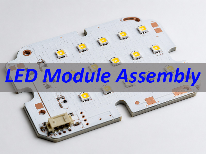
LED Module Assembly

What Is LED Module Assembly?

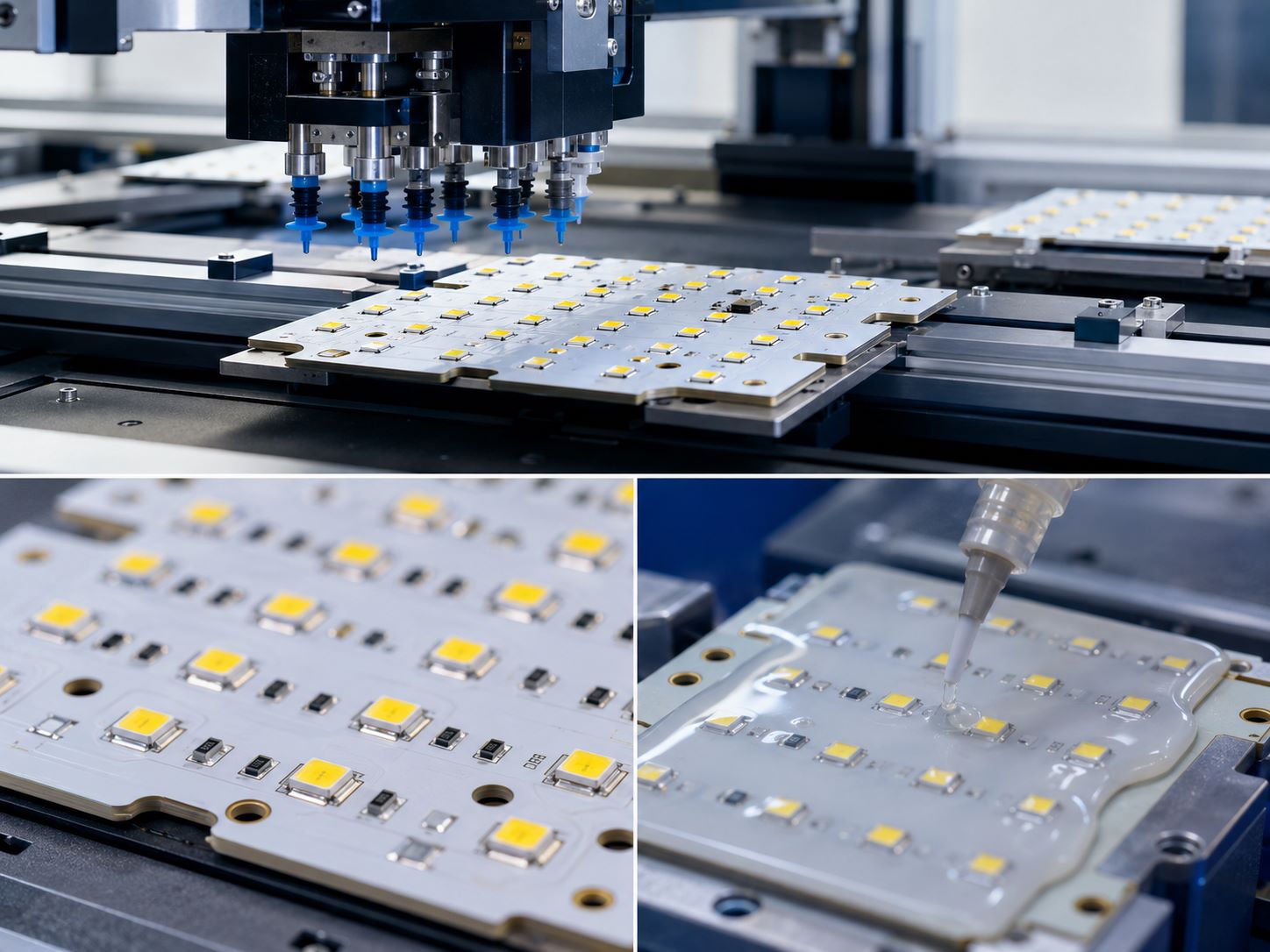
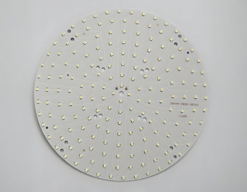
LED module assembly is the process of turning a bare LED PCB into an assembled lighting board. It usually includes PCB fabrication, solder paste printing, SMT LED mounting, lead-free reflow soldering, inspection, testing, and sometimes protective coating.

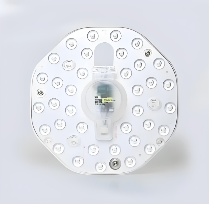
In PCB manufacturing, an LED module does not always mean a complete finished lamp. It usually means the LED board inside the product. The housing, lens, driver, thermal structure, final packaging, and product certification may still belong to the customer’s final product scope.

This distinction matters. If you need only the bare board, you are requesting LED PCB or MCPCB fabrication. If you need LEDs mounted and tested, you are requesting LED module assembly or LED PCB assembly.

ItemLED PCBLED Module
StatusBare boardAssembled lighting board
LEDsNot mountedMounted and soldered
FunctionCannot light up aloneCan be powered and tested
Main servicePCB fabricationPCB + SMT assembly
Quality focusMaterial, copper, finishSoldering, polarity, function
LED Module Assembly

Why Are MCPCBs Used in LED Lighting Boards?

LEDs generate heat during operation. If heat stays near the LED package and solder joint, the module may face faster brightness decay, color shift, solder stress, or early failure. That is why many LED lighting boards use MCPCBs, especially aluminium core PCBs.

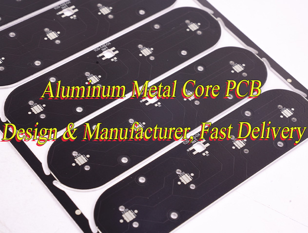
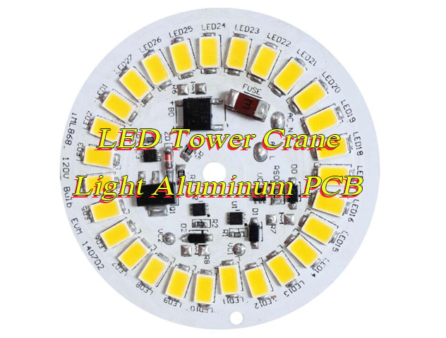
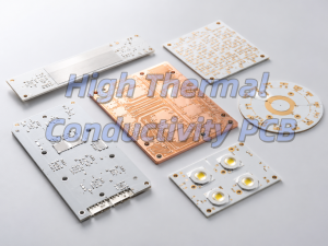
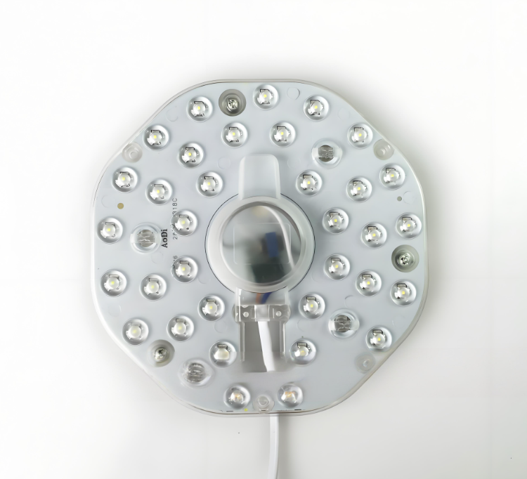
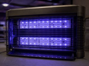
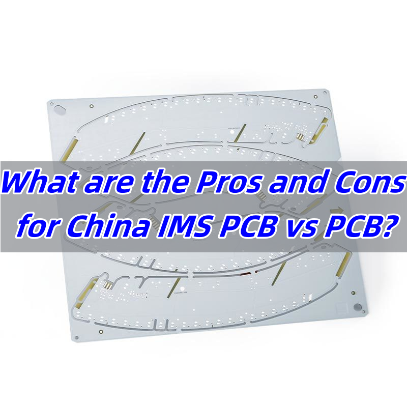
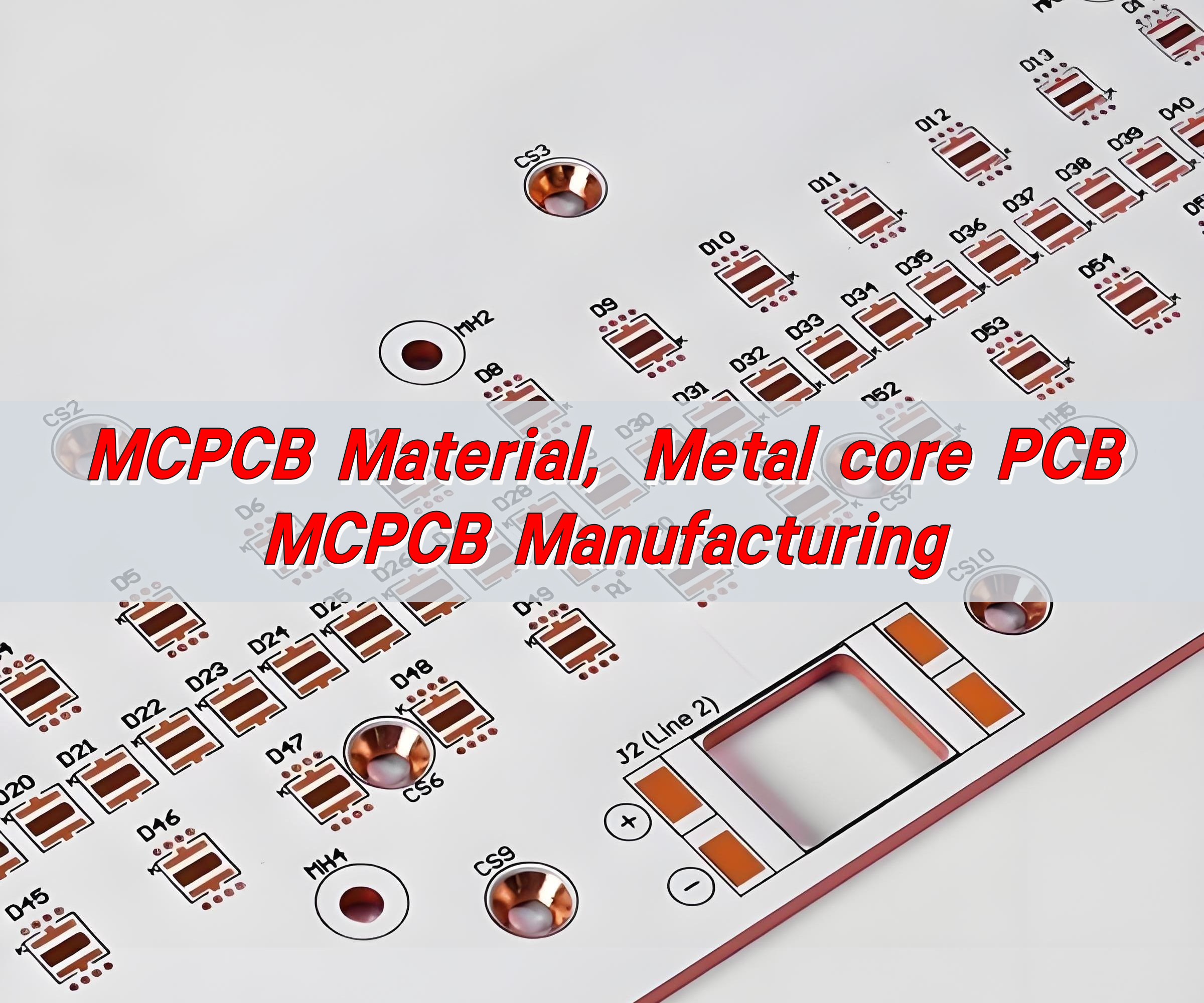
A metal-core PCB gives heat a better path from the LED pad area toward the metal base. This is especially useful for compact lighting boards, circular LED modules, UV LED boards, insect trap modules, and higher-power LED applications.

Thermal FactorFR4 ExampleIMS / MCPCB ExampleMeaning
Thermal conductivityAbout 0.25 W/m·KAbout 3 W/m·K dielectricBetter heat transfer
Junction-to-ambient thermal resistance61.56°C/W39.1°C/WLower thermal resistance
Main roleCircuit carrierCircuit carrier + heat-spreading baseMore suitable for many LED boards

This does not mean every LED board must use aluminum PCB. Low-power LED boards may still use FR4. But when heat, service life, compact space, or continuous operation matters, MCPCB is often the safer starting point.

The PCB manufacturer’s role is to build the selected board structure correctly: metal base, dielectric layer, copper thickness, solder mask, surface finish, outline, flatness, and solderability.

How Does LED Module Assembly Work?

A good LED module starts with file review. Before production, the manufacturer should check the Gerber files, BOM, pick-and-place file, LED datasheet, polarity information, coating requirement, and testing requirement.

After that, the MCPCB is fabricated, LEDs are prepared, solder paste is printed, LEDs are placed by SMT equipment, and the board goes through lead-free reflow soldering. After reflow, the module is inspected, tested, and coated if required.

A practical flow looks like this:

StepWhat to Check
File reviewGerber, BOM, polarity, coating area
MCPCB fabricationMaterial, copper, finish, flatness
LED preparationPart number, bin, reel label, polarity
SMT mountingPaste volume, placement, reflow profile
InspectionVisual, AOI, polarity check
TestingElectrical and power-on test
CoatingArea, thickness, keep-out zones

The process is straightforward, but the risk is in the details. Wrong LED polarity, unstable solder paste volume, poor pad wetting, or unclear coating areas can all create defects during batch production.

What Affects LED SMT Assembly Quality?

LED SMT quality depends on PCB solderability, LED package condition, solder paste control, placement accuracy, and reflow stability.

The first key point is polarity. LEDs are directional components. If polarity is reversed, the module may not light up. Polarity should be clear in the datasheet, BOM, assembly drawing, and first article inspection.

The second key point is solder volume. Too much solder can cause LED tilt or movement. Too little solder can create weak joints. On aluminum PCBs, the metal base also affects heat absorption during reflow, so the reflow profile should be verified with the actual board when needed.

The third key point is LED bin control. For lighting boards, mixed LED bins can cause visible brightness or color differences even if every LED turns on.

RiskResultControl Point
Wrong polarityLED does not lightPolarity check
Too much solderTilt or shiftingStencil and paste control
Too little solderWeak jointPaste process control
Poor wettingUnstable solderingSurface finish and reflow
Mixed LED binsColor or brightness mismatchReel and bin traceability

For customer-supplied LEDs, the assembler should confirm reel labels, bin codes, polarity marks, storage condition, and spare quantity before production.

How Does PCB Layout Support Heat Dissipation?

PCB layout can support heat dissipation, but it does not replace full lamp thermal design. This boundary should be clear.

From the PCB and PCBA side, the focus is on manufacturable details: LED thermal pad connection, copper area, current path width, solder mask opening, pad solderability, board flatness, and MCPCB material selection.

A typical heat path in an aluminum PCB LED module is:

LED package → solder joint → copper pad → thermal dielectric layer → aluminum base → housing or air.

The PCB/PCBA manufacturer can support the first part of this path through board fabrication and SMT quality control. But final temperature still depends on the customer’s housing, heat sink, airflow, screw pressure, thermal interface, LED current, and working environment.

So the right message is not “we design the whole lamp thermal system.” The right message is: the PCB and assembly process help build a stable thermal path inside the LED lighting board.

When Is Protective Coating Needed?

Protective coating is useful when LED modules may face moisture, dust, insects, condensation, cleaning exposure, or semi-outdoor conditions. This is common in insect light traps, industrial lighting, agricultural lighting, and boards used in harsh environments.

Silicone conformal coating is often used on LED boards because it is flexible and suitable for environmental protection. But coating must be controlled carefully.

Coating TypeTypical Thickness Range
Acrylic / Epoxy / Urethane0.03–0.13 mm
Silicone0.05–0.21 mm
Parylene0.01–0.05 mm

The coating drawing should define where coating is required and where it must be avoided. Connectors, test points, screw holes, contact areas, and optical surfaces may need keep-out zones.

Poor coating control can create bubbles, uneven appearance, blocked connectors, contaminated pads, or reduced light performance. For LED modules, coating is both a protection process and a quality-control point.
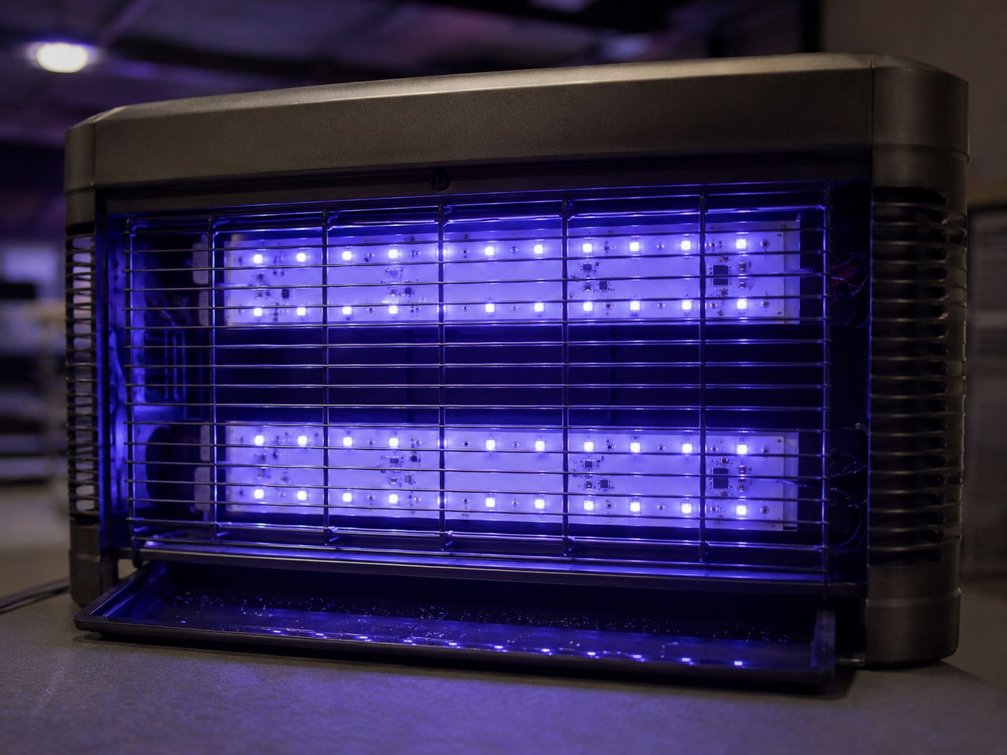
LED Module Assembly

How Should LED Modules Be Tested?

Power-on testing is necessary, but it is not the whole quality check. A module can light up and still have weak solder joints, mixed LED bins, coating defects, or unstable current.

A practical LED module test plan may include:

Test ItemPurpose
Visual inspectionCheck appearance and contamination
AOICheck placement and visible solder joints
Polarity checkPrevent reversed LEDs
Electrical testCheck shorts, opens, continuity
Power-on testConfirm light-up function
Current checkConfirm operating condition
Coating inspectionCheck coverage and keep-out areas
Sample agingFind early failures before shipment

The test scope should match the application. A simple indoor board may need basic testing. A higher-reliability or semi-outdoor lighting board may need stricter inspection, current checks, coating inspection, and sample aging.

Buyers should define test voltage, current limit, inspection standard, coating acceptance criteria, and aging requirement before quotation.

What Should Buyers Prepare Before an LED Module RFQ?

A clear RFQ helps the supplier quote faster and avoid wrong assumptions. For early discussion, a rough drawing may be enough for a ballpark estimate. For formal quotation, complete engineering files are needed.

Useful RFQ documents include:

RFQ FileWhy It Matters
Gerber and drill filesPCB fabrication
BOMComponent and assembly review
Pick-and-place fileSMT programming
LED datasheetPackage, polarity, soldering data
Assembly drawingPlacement and special notes
Coating drawingCoating and keep-out control
Test requirementInspection and quotation scope
QuantityPrice and lead time

If LEDs are supplied by the customer, also provide part number, manufacturer, reel label, bin code, polarity mark, storage condition, MSL information if applicable, and spare quantity for SMT loss.

The more complete the RFQ, the easier it is to confirm feasibility, sample lead time, production cost, and quality control.

LED Module Assembly Case Study: How Does EBest Circuit Support MCPCB and SMT Projects?

A practical LED module assembly project often starts with a clear board specification. For one LED lighting board project, EBest Circuit supported a single-sided aluminum PCB with 2.0 mm finished thickness, 2 W/m·K thermal conductivity, 2 oz copper, white solder mask, black legend, and OSP surface finish.

Board RequirementSpecificationAssembly Value
PCB structureSingle-sided aluminum PCBLED board base
Finished thickness2.0 mm ±10%Board rigidity
Thermal conductivity2 W/m·KHeat transfer
Copper weight2 ozCurrent support
Solder maskWhite solder maskLight reflection
LegendBlack legendClear marking
Surface finishOSPSMT soldering

For this type of LED module assembly, the focus is not only PCB fabrication. The assembly process also needs to control LED polarity, solder paste volume, placement accuracy, and reflow soldering. If silicone conformal coating is required, the coating area and keep-out zones should be confirmed before production.

In this project type, EBest Circuit’s role is focused: manufacture the MCPCB, support SMT LED mounting, control soldering quality, and prepare the assembled lighting board for the customer’s next production step. The final lamp housing, optics, driver system, and product-level thermal validation remain part of the customer’s complete product design.

This case shows why LED module assembly should be evaluated as a combined PCB and SMT PCB manufacturing process. Board material, copper weight, surface finish, LED placement, and testing all affect the final reliability of the lighting board.

Why Choose EBest Circuit (Best Technology) for LED Module Assembly?

For LED module assembly projects, buyers need more than an SMT supplier who can simply place LEDs. A reliable LED lighting board often involves PCB fabrication, component control, SMT assembly, soldering quality, protective coating, inspection, and production traceability. When these steps are handled by separate suppliers, communication gaps and production risks can increase.

EBest Circuit (Best Technology) supports LED lighting board projects with an integrated PCB and PCBA manufacturing approach. Before production, our team can review Gerber files, BOM, pick-and-place data, LED datasheets, coating requirements, and test requirements to help customers identify potential manufacturing issues during the sample stage.

AdvantageValue for LED Module Assembly
PCB + PCBA factoriesFewer handoff risks
MCPCB and LED board experienceBetter process understanding
DFM and BOM reviewEarlier issue detection
SMT LED mountingPrototype to batch support
Consigned LED supportCustomer-specified parts
Coating and testing supportMore complete delivery
Digital traceabilityBatch and progress tracking
Quality certificationsHigher quality control needs

These advantages apply to different LED lighting board projects, including aluminum LED boards, FR4 LED boards, UV LED modules, industrial lighting boards, insect trap LED modules, customer-supplied LED assembly projects, and LED modules that require protective coating or basic function testing. The board material, copper weight, surface finish, LED package, and test requirements may vary, but the goal is the same: helping customers move from design files to controlled production.

EBest Circuit’s value is not claiming to design the complete finished lamp. Our focus is LED lighting board manufacturing: PCB fabrication, SMT LED mounting, process review, consigned material handling, coating support, inspection, and basic testing. The final lamp housing, optics, driver system, and product-level thermal validation remain part of the customer’s complete product design.

With 20 years of PCB and PCBA manufacturing experience, engineering support, quality systems, and traceable production management, EBest Circuit helps customers move LED lighting board projects from sample validation to more stable batch production.

FAQs About LED Module Assembly

What is LED module assembly?

LED module assembly is the process of fabricating an LED PCB, mounting LEDs and related components, soldering them, inspecting the board, and testing the assembled lighting board.

Is LED module assembly the same as finished lamp manufacturing?

No. LED module assembly usually focuses on the lighting board. Finished lamp manufacturing may also include housing, optics, driver integration, mechanical assembly, labeling, packaging, and product-level certification.

Why are aluminum PCBs used for LED modules?

Aluminum PCBs are used because they provide a better thermal path than standard FR4 in many LED lighting applications.

Can customer-supplied LEDs be used?

Yes. Consigned LEDs can be used if the buyer provides clear part numbers, reel labels, bin codes, polarity information, storage details, and enough spare quantity for SMT process loss.

What is silicone conformal coating used for?

Silicone conformal coating helps protect LED modules from moisture, dust, insect contamination, and environmental exposure.

What files are needed for a quote?

Gerber files, BOM, pick-and-place file, assembly drawing, LED datasheet, coating drawing, test requirements, and quantity are usually needed.

To summarize, LED module assembly is not only about mounting LEDs. A reliable lighting board depends on MCPCB material, copper layout, soldering quality, LED polarity, component traceability, protective coating, and defined testing.

For buyers, the better partner is not simply a supplier who can place LEDs. It is a PCB and PCBA manufacturer who understands how board fabrication and SMT assembly affect LED module reliability.

EBest Circuit supports LED lighting board projects with MCPCB fabrication, SMT LED mounting, consigned LED handling, conformal coating, and basic module testing. Pls feel free to send your Gerber files, BOM, pick-and-place data, LED datasheets, coating requirements, and test requirements to sales@bestpcbs.com for review.

You may also like

LED PCB Assembly Manufacturer & Supplier |EBest Circuit (Best Technology)
Monday, August 11th, 2025

What is LED PCB assembly? Let’s explore its definition, types, applications, assembly steps, how to choose LED PCB assembly service.

Are you troubled with these problems?

  • Heat Dissipation Challenges: How can high-power LED PCB assemblies effectively dissipate heat to prevent light decay and shortened lifespan?
  • Cost Pressures: How can we reduce material and production costs while ensuring LED PCB assembly quality?
  • Design Limitations: How can traditional PCB assemblies achieve flexible adaptation and innovative design in complex lighting scenarios?

EBest Circuit (Best Technology) can provide service and solutions:

  • Efficient Heat Dissipation Solutions: Utilizing highly thermally conductive metal substrates (such as aluminum substrates) and optimized heat dissipation structure design ensures long-term stable operation of LED PCB assemblies, reducing temperatures by over 20%.
  • Cost-Optimized Processes: Through refined production management and material selection strategies, we provide customers with cost-effective LED PCB assembly solutions, saving 15%-30%.
  • Customized Design Services: Supporting specialized designs such as custom-shaped boards to meet diverse lighting needs and help customers create differentiated products.

Welcome to contact us if you have any request for LED PCB assembly: sales@bestpcbs.com.

What Is LED PCB Assembly?

LED PCB assembly refers to the complete manufacturing process of soldering light-emitting diodes (LEDs) and other electronic components onto printed circuit boards (PCBs) using surface mount technology (SMT) or through-hole (DIP) technology. This process includes key steps such as solder paste printing, component placement, reflow soldering, optical inspection, and functional testing. Ultimately, the LED lighting or display module is completed with both electrical connections and physical support. This process requires strict control of soldering quality, heat dissipation, and optical consistency to ensure the reliability and lifespan of the LED product.

What Is LED PCB Assembly?

Types of LED Lighting PCB Assembly

Surface Mount Technology (SMT):

  • Definition: LED components are soldered directly onto the PCB surface using a placement machine, suitable for small, high-density designs.
  • Advantages: High efficiency, low cost, and support for ultra-thin lighting fixtures (such as light strips and panel lights).
  • Applications: Indoor consumer lighting (downlights and spotlights).

Through-Hole Technology (THT):

  • Definition: LED pins penetrate PCB holes and are secured by wave soldering. Traditional yet reliable.
  • Advantages: High mechanical strength and vibration resistance, suitable for high-power modules (such as street lights and mining lamps).
  • Applications: Outdoor and industrial lighting.

Hybrid Assembly (SMT + THT)

  • Definition: SMT control chip and THT high-power LED, balancing performance and reliability.
  • Advantages: Supports driver circuit integration (such as constant current source), suitable for smart lighting.
  • Applications: Smart bulbs, adjustable color temperature lamps.
Types of LED Lighting PCB Assembly

Applications of LED PCB Assembly

  • Commercial/Residential Lighting: High-brightness LED panels (such as downlights and panel lights) with dimming and color adjustment capabilities.
  • Stage and Entertainment Lighting: Concert and theater lighting systems (DMX512 protocol control).
  • Automotive Lighting: Headlight modules (daytime running lights, turn signals), instrument panel backlight units.
  • Outdoor Displays: Billboards, traffic lights, and stadium display backlight units.
  • Medical Equipment: Surgical shadowless lamps, diagnostic instrument indicators, and UV disinfection equipment.
  • Industrial Control: Machine vision light sources, safety indicator systems, and automated equipment status displays.
  • Consumer Electronics: TV/monitor backlight units, mobile phone flashlights, and wearable device indicators.
  • Special Environment Lighting: Explosion-proof lamps for mining, low-temperature lighting for cold storage, and waterproof light panels for ships.

LED PCB Assembly Process Steps

1. Material Preparation

  • Cut the substrate (aluminum substrate/flexible board) to size and clean the surface.
  • Sort the LED components, resistors, driver chips, etc. according to the bill of materials (BOM).

2. Component Placement

  • SMT/COB: SMT machine places LED components (accuracy ±0.1mm). COB bonding chips are then coated with phosphor adhesive and cured.
  • THT: Insert LED pins into PCB holes using a plug-in machine or manually.

3. Soldering

  • SMT/COB: Reflow soldering (220–250°C) ensures full solder joints.
  • THT: Wave soldering (260–280°C) ensures a solder fill rate of ≥75% for through-holes.

4. Cleaning and Curing

  • Ultrasonic cleaning removes flux, followed by drying (80°C/10 minutes).
  • Flexible PCB secondary curing (120°C/2 hours) enhances adhesive adhesion.

5. Electrical Testing

  • A multimeter/ICT is used to check LED voltage, resistance, and short/open circuits.
  • Drive Circuit Testing: Constant current source accuracy of ±3%, dimming function verification.

6. Optical and Thermal Testing

  • An integrating sphere is used to measure luminous efficacy (lm/W), color temperature (±100K), and color rendering index (Ra ≥ 80).
  • A thermal imager is used to monitor LED junction temperature rise (≤ 85°C).

7. Aging Quality Inspection

  • 72 hours of continuous aging (rated power/60°C), eliminating modules with a lumen decay of ≥ 5% or faults.
  • Appearance Inspection: Smooth solder joints and no deformation of the substrate.

8. Packaging:

  • Packaged in an anti-static bag, with parameters (power, color temperature) and safety certifications marked.
  • A test report (luminous efficacy, temperature rise, aging data) and installation instructions are included.
LED PCB Assembly Process Steps

What Should You Look for When Choosing LED PCB Assembly Service?

Process Compatibility & Technical Expertise

  • Support for SMT, COB, THT, flexible PCB, and hybrid assembly processes to accommodate diverse LED products (e.g., high-density light strips, high-power streetlights).
  • Precision equipment: placement accuracy ≥ ±0.05mm, reflow soldering temperature control (220–250°C), wave soldering (260–280°C) for reliable joints.
  • Thermal simulation (ANSYS/FloTHERM), DFM optimization, and BOM standardization to preempt design flaws (e.g., pad orientation aligned with panelization to prevent wire bonding damage).

Quality Control & Inspection Protocols

  • Adherence to IPC-A-610 standards, with AOI, X-ray inspection (solder joint void rate ≤5%), and ICT for electrical performance verification.
  • Environmental testing: thermal shock (-40°C~125°C/1000 cycles), 85°C/85%RH humidity resistance (1000 hours), and aging tests (72-hour continuous operation, ≤5% lumen degradation).
  • Full material traceability, ensuring RoHS/halogen-free compliance and waste management practices.

Certifications & Regulatory Compliance

  • ISO 9001 certification for quality management; IATF 16949 (automotive) or ISO 13485 (medical) for industry-specific compliance.
  • Use of lead-free solder, eco-friendly substrates, and third-party environmental reports.

Production Capacity & Delivery Efficiency

  • 24-hour prototype turnaround, small-batch production (48-hour lead time), and monthly output ≥100,000 sq.ft.
  • Multi-modal logistics (air/ground freight) with ≥95% on-time delivery; BOM sourcing and consignment stock support.

Industry Experience & Client References

  • Proven expertise in automotive, medical, and smart home sectors with tailored solutions (e.g., modular designs, thermal management optimization).
  • Partnerships with Tier 1 suppliers or automotive OEMs (e.g., Ford, Toyota); case studies demonstrating defect resolution (e.g., solder paste curing issues, low-temperature solder cracking).

Cost Optimization & After-Sales Support

  • Transparent pricing with BOM cost breakdowns and customizable quotation structures.
  • Cost-saving strategies: material substitution (e.g., embedded heat pipes vs. thick copper) and process improvements (e.g., hybrid assembly for labor reduction).
  • 24/7 failure analysis, rapid replacement, and NDA-backed design confidentiality.
What Should You Look for When Choosing LED PCB Assembly Service?

Why Choose EBest Circuit (Best Technology) as LED PCB Assembly Manufacturer?

Reasons why choose us as LED PCB assembly manufacturer:

  • Competitive Pricing: Our direct supply model eliminates middlemen, reducing bulk order costs by 15%-20% with no hidden fees.
  • Environmentally Friendly Materials and Processes: Utilizing 25% recycled aluminum and lead-free processes, we comply with RoHS/REACH standards and reduce raw material costs.
  • 24-Hour Rapid Prototyping: LED PCB samples are delivered within 24 hours, shortening the development cycle for a stage lighting project by 50%.
  • Quality Certification: ISO 9001/IATF 16949/ISO 13485 certified, making us suitable for demanding applications such as medical and automotive.
  • Strict Quality Control: 100% automated inspection with Automated Optical Inspection (AOI) ensures a solder joint defect rate of <0.01%, extending the LED board lifespan to over 50,000 hours.
  • Free Design for Function (DFM) Optimization: Pre-review design files to identify issues such as insufficient thermal vias and close copper spacing, reducing design revisions and development costs by 30%.
  • Turnkey Solution: This one-stop service covers the entire process, including PCB layout (compatible with Altium/PADS), thermal simulation (ANSYS Icepak), and SMT assembly.
  • 24/7 engineering response: Thermal runaway and EMC interference issues are resolved within an average of 4 hours, ensuring zero downtime for on-site projects.

Our LED PCB Assembly Capabilities

Item Capabilities
Placer Speed 13,200,000 chips/day
Bare Board Size 0.2 x 0.2 inches – 20 x 20 inches/ 22*47.5 inches
Minimum SMD Component 01005
Minimum BGA Pitch 0.25mm
Maximum Components 50*150mm
Assembly Type SMT, THT, Mixed assembly
Component Package Reels, Cut Tape, Tube, Tray, Loose Parts
Lead Time 1 – 5 days

How to Get a Quote for LED PCB Assembly Service?

LED PCB Assembly Quote Required Documents

1. Design Files:

  • Gerber Format PCB Layout File + Bill of Materials (BOM) (including component specifications)

2. Technical Specifications:

  • PCB Layer Count, Dimensions, and Copper Thickness Requirements
  • Surface Finish (HASL/ENIG/OSP)
  • Special Requirements (e.g., thermal via design, impedance control)

3. Order Information:

  • Estimated Quantity (Sample/Small Batch/Mass Production)

4. Delivery Time Requirements

  • Certification Requirements (if applicable): RoHS/REACH, ISO, IATF 16949, etc.

Why Choose EBest Circuit (Best Technology)?

  • Free DFM: Identify design risks early and reduce development costs
  • Transparent Quotation System: No hidden fees, 15%-20% cost savings for bulk orders
  • Full Process Control: From PCB manufacturing to SMT assembly, one-stop service

Get Started Now! Welcome to contact us if you have any inquiry for LED PCB assembly: sales@bestpcbs.com.

You may also like

LED PCB Assembly, LED PCB Assembly Manufacturers
Tuesday, April 8th, 2025

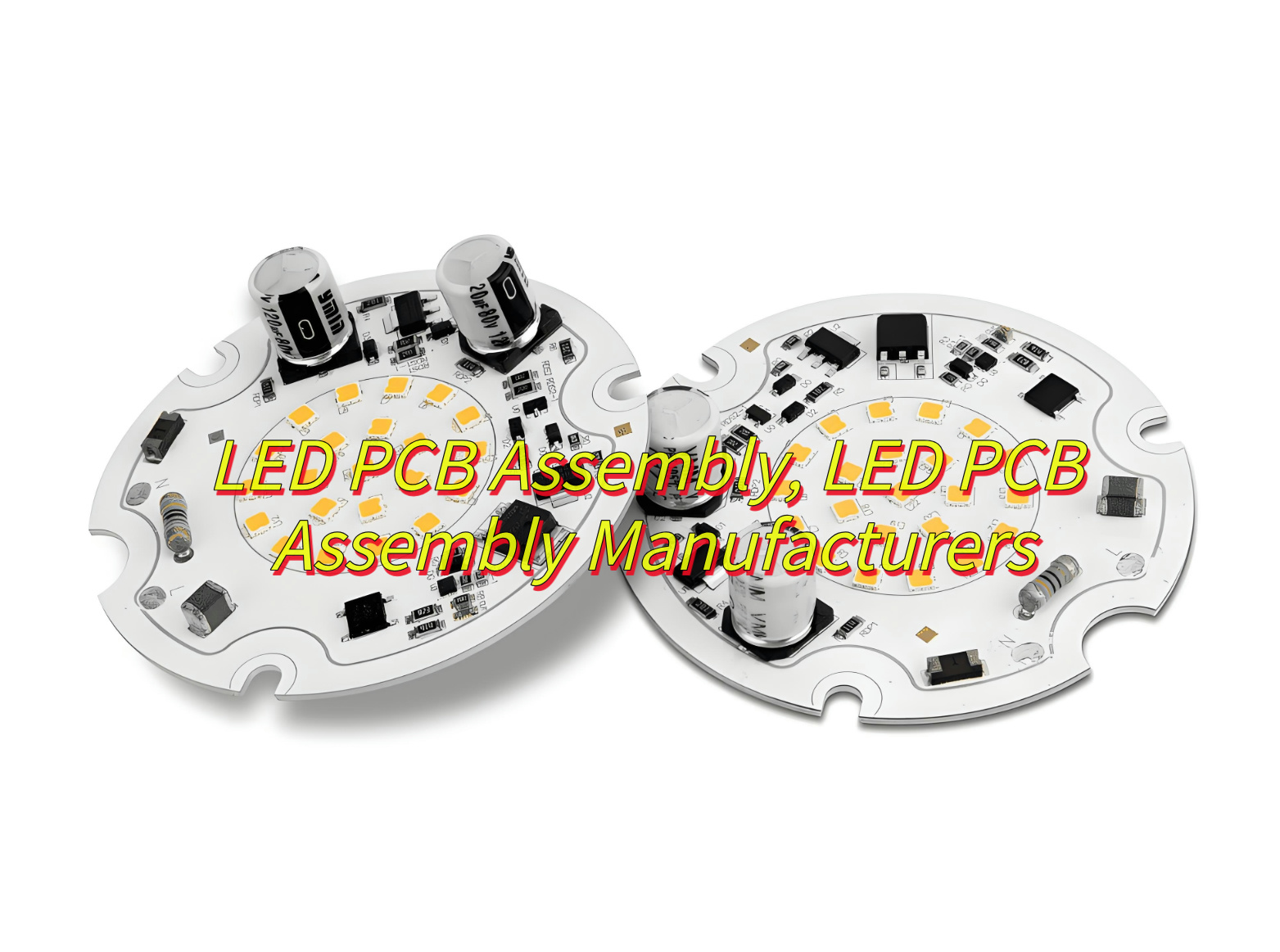
Are you find a LED PCB assembly solution? How do you find a good quality LED PCB assembly factory? This blog breaks down the essentials: assembly machines, assembly processes and cost, and how to select a reliable LED PCB manufacturer.

Best technology, we focus on LED PCB assembly over 18 years. We can achieve LED PCB fast assembly (48-72hours fast delivery) by our stable electronics supply chains and our four SMT full-automatic production lines. So we are able to ensure consistency in luminous efficiency at fast assembly. Then all the LED PCB we assembled will be full inspected before and after assembly to reduce reworking cost. If you have any request for LED PCB, please feel free to contact us. sales@bestpcbs.com

What Is LED PCB Assembly?

LED PCB assembly refers to the process of mounting LED components onto printed circuit boards (PCBs) to create functional lighting systems or electronic devices. This process combines surface-mount technology (SMT) with precision soldering to ensure reliable electrical connections. Key elements include PCB material selection (e.g., aluminum or flexible substrates), component placement accuracy, and thermal management solutions. Manufacturers specialize in this field offer end-to-end services, from design to mass production, catering to applications like LED lighting, automotive displays, and consumer electronics.

What Is LED PCB Assembly?

What Are the Advantages of HASL Lead-free for LED PCBA?

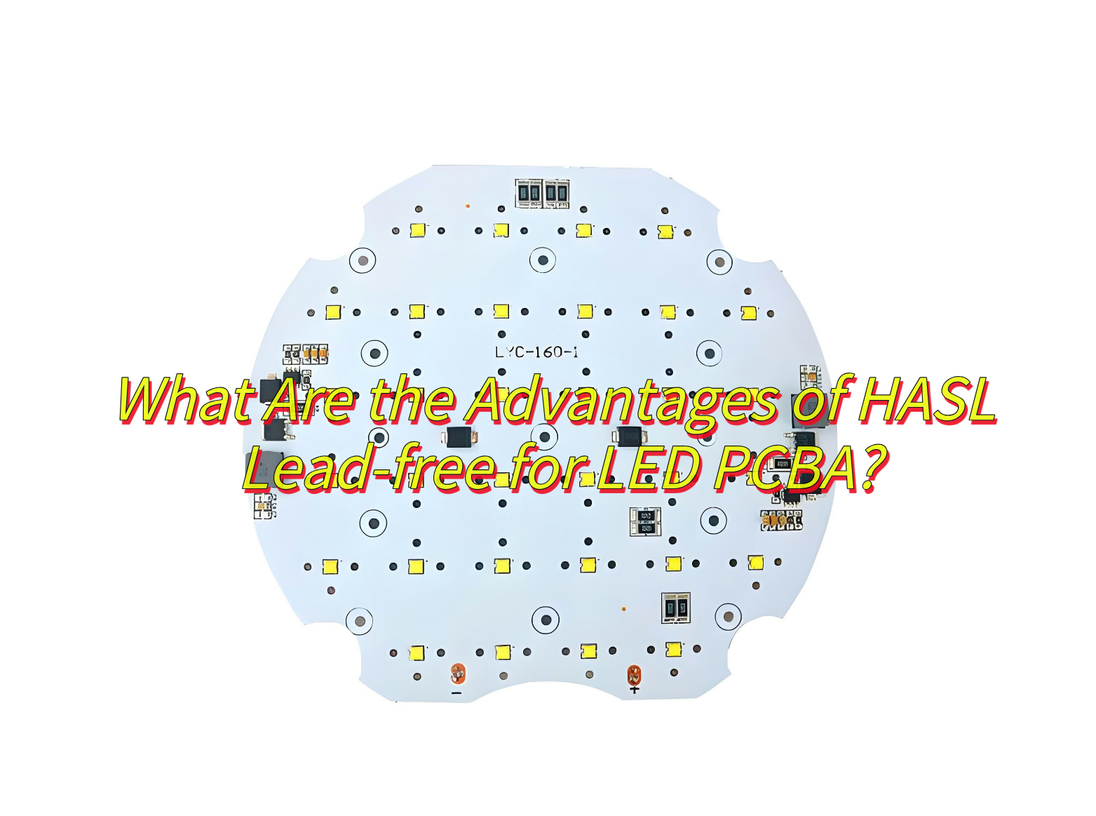
  • Environmental Compliance: Complies with the RoHS directive, eliminates lead pollution, meets global environmental regulations, and is suitable for markets with strict environmental requirements such as consumer electronics.
  • High Reliability: Withstands thermal cycling from -55°C to 100°C, suitable for LED applications; the tin layer prevents copper oxidation, enhancing long-term stability; good wettability in the first reflow, resulting in high soldering quality.
  • Significant Cost-Effectiveness: Lower cost than Electroless Nickel Immersion Gold (ENIG), suitable for medium-budget projects; mature process, suitable for mass production, reducing unit costs; long shelf life (stable for one year under moisture-proof conditions), reducing storage and rework risks.
  • Processing Convenience: Compatible with single/double-sided and multilayer boards (1-26 layers), meeting complex design requirements; short production cycle (12-20 days), suitable for quick delivery; solder joint defects can be repaired with hot air, reducing scrap rates.
  • Long-Term Technical Advantages: Mature technology, high stability, suitable for the LED industry’s needs; reliability can be enhanced by adding a nickel layer or optimizing solder paste formulations.
What Are the Advantages of HASL Lead-free for LED PCBA?

What Assembly Machine Is Used in the LED PCBs Assembly Process?

  • Pick-and-place machine
  • Reflow oven(Nitrogen reflow is optional, it is very stable but the cost of this kind of assembly machine is much higher than normal reflow oven)
  • Solder paste printer
  • SPI inspection machine
  • AOI inspection machine
  • X-Ray inspection machine
  • Conformal coating machine
  • Functional testing equipment

What Are 5050 LED PCB Assembly Process Steps?

Here’s a streamlined list of the 5050 LED PCB assembly process steps:

1. Incoming inspection of LED/materials

  • Use a two-dimensional measuring instrument and a film thickness tester to check the appearance size of the LED bracket, the thickness of the electroplating layer, and the oxidation phenomenon ‌.
  • Verify the specifications of the 5050 LED (package size 5.0×5.0×1.6mm, polarity identification) and the IC model (such as SK6812) ‌.

2. Baking materials

  • Unopened LEDs need to check the air tightness of the packaging, and complete the soldering within 24 hours after opening; if moisture is absorbed, it needs to be baked at 60℃ for 24 hours ‌.
  • Pre-bake the PCB board (120℃/2H) to remove moisture ‌.

3. Pick and Place & Solder paste printing

  • Use a laser steel mesh to print SAC305 lead-free solder paste, with a thickness control of ±10μm ‌
  • Clean the steel mesh regularly to avoid clogging and uneven printing ‌.

4. SPI Inspection

  • Use 3D optical detection of solder paste volume, coverage area, and offset to ensure printing quality.

5. SMT( Surface Mounted Technology)

  • IC (such as WS2812B) and small resistors and capacitors are mounted first, and 5050 LED is mounted last.
  • Check that the polarity mark (cathode/anode) is aligned with the PCB silk screen.

6. Reflow soldering

  • Preheating (150–180℃/60–90s) → Constant temperature (180–220℃/60–120s) → Reflow peak (240–260℃/10–30s) → Cooling (slope ≤4℃/s).

7. Post-furnace inspection ‌

  • Visually check for offset, tombstone, and cold soldering.
  • Use an anti-static soldering iron (temperature ≤260℃/time ≤3 seconds) for manual correction.

8. AOI (Automatic Optical Inspection) ‌& X-Ray inspection(Optional) ‌

  • AOI: Scan solder joint integrity, LED polarity, and component missing, and mark defective products for repair.
  • X-Ray: Detect pores or cracks in hidden solder joints (such as LED heat sink pads) to ensure heat dissipation performance.

9. Post-soldering & Cleaning

  • Limited to rework scenarios, soldering iron temperature ≤300℃, avoid touching the LED colloid.
  • Wipe with isopropyl alcohol (IPA) or low-residue solvent, and disable ultrasonic cleaning (to prevent damage to LED colloid).

10. Testing & Conformal coating ‌

  • Electrical test: 5V drive current (60mA/LED), RGB color consistency.
  • Signal test: verify address control protocol (such as PWM dimming).
  • Conformal coating: Spray acrylic or silicone conformal coating, and enhance moisture and sulfur corrosion resistance after curing. ‌

11. Box Building Assembly &  Packaging and shipment ‌

  • Assemble the LED PCB with the heat sink and the housing to ensure that the contact surface is flat. ‌
  • Packaging with vacuum moisture-proof bag/bubble bag/custom blister box, and marking the outer box with shockproof/sulfur-proof logo.

How to Choose A High Quality LED PCB Assembly Manufacturer?

Here are some ways of how to choose a high quality LED PCB assembly manufacturer:

  • Certified Quality Assurance-The manufacturer holds international certifications like ISO 9001, ISO 14001, and UL, ensuring their quality management system and products meet global standards.
  • Advanced Technical Capabilities-They possess state-of-the-art equipment and technology, such as AOI machines and X-ray detection, enabling precise and high-quality production. They can also handle special processes like HDI boards and rigid-flex boards.
  • Rigorous Quality Control-A comprehensive quality control process is in place, covering incoming material inspection, in-process inspection, and final product testing. Reliability tests ensure the PCB’s stability and durability.
  • Flexible Production Capacity-The manufacturer can handle both small and large orders, adapting to different complexities and changes in demand, ensuring timely delivery.
  • Excellent Customer Service-They provide responsive communication, prompt technical support, and engineering assistance, such as DFM analysis, to help optimize your design and ensure a smooth production process.

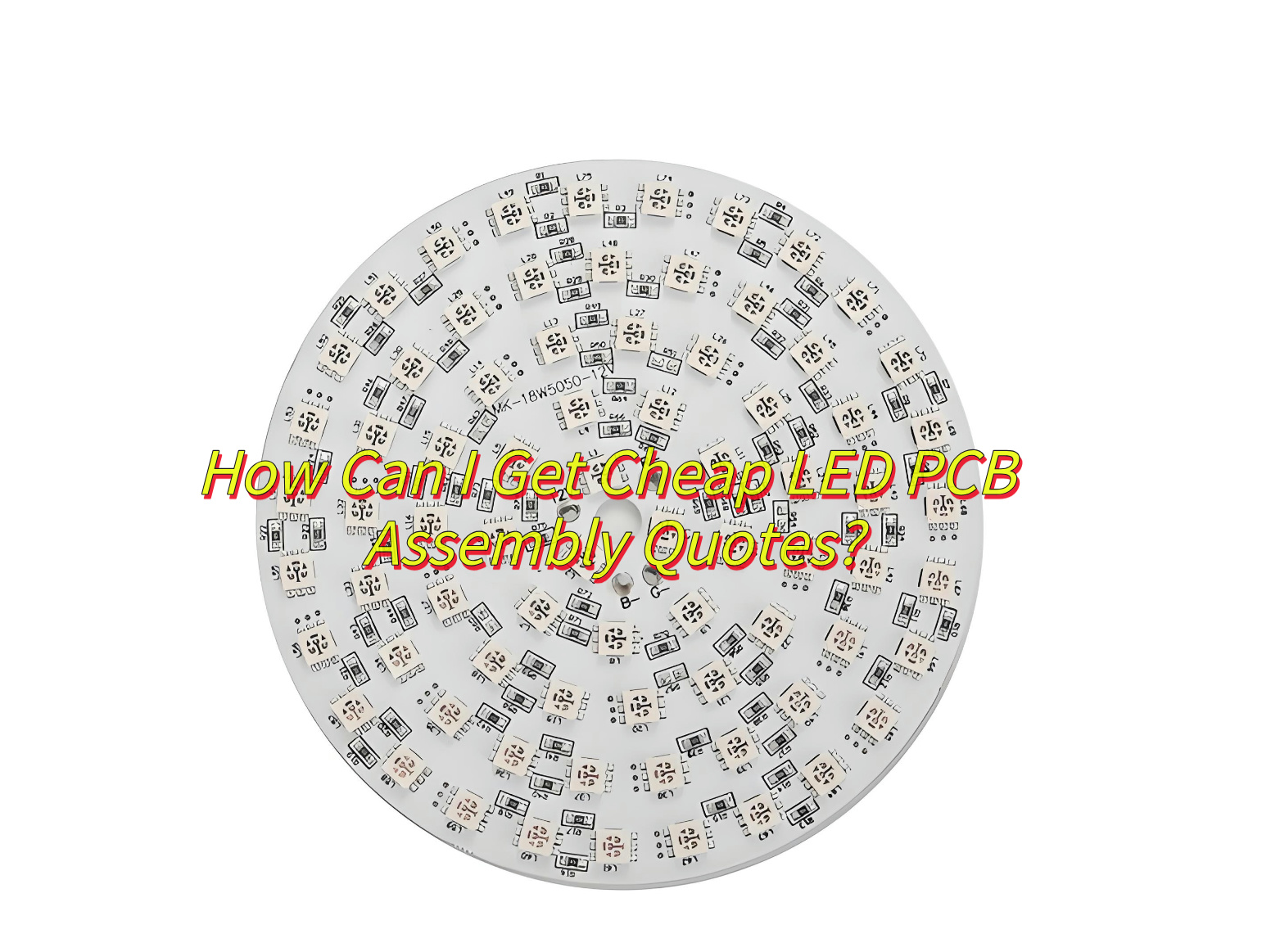
How Can I Get Cheap LED PCB Assembly Quotes?

To get cheap LED PCB assembly quotes, follow these steps:

  • Compare Multiple Manufacturers: Contact several manufacturers to compare prices and services.
  • Provide Detailed Specifications: Clearly outline your PCB requirements, including layer count, material, and components.
  • Optimize Your Design: Simplify your PCB design to reduce costs.
  • Order in Bulk: Larger orders often qualify for volume discounts.
  • Build Long-Term Relationships with one supplier: Negotiate better rates by committing to repeat business.
How Can I Get Cheap LED PCB Assembly Quotes?

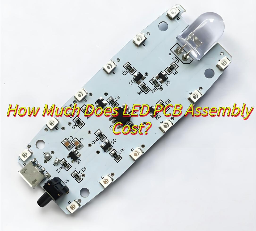
How Much Does LED PCB Assembly Cost?

Here is a LED PCB Assembly pricelist:

  • Setup fee: Around $200 ‌
  • Placement cost: Around $0.01-$0.05 per component ‌
  • Standard LEDs (e.g., 5050 RGB): Around $0.10-$5 per unit ‌
  • Specialty LEDs (e.g., SK6812): Around $0.50-$5 per unit ‌
  • Solder Paste Stencil‌:Around $100 ‌
  • AOI Testing: Around $50-$100 per batch ‌
  • Functional testing: Around $100 per batch ‌
  • Conformal Coating‌: Around $1-$10 per board ‌
  • Packaging‌: Around $3-$7 per unit
How Much Does LED PCB Assembly Cost?

Note‌: Prices assume mid-range specifications and bulk orders. For exact quotes, please provide BOM and Gerber files with EBest Circuit (Best Technology).

What Are Differences Between Aluminum and Flex LED PCB Assembly?

Here are the main differences between Aluminum and Flex LED PCB Assembly:

  1. Material and Structure
    Aluminum PCB: Uses an aluminum base for heat dissipation, suitable for high-power LEDs.
    Flex PCB: Made of flexible materials, allowing bending and complex shapes.
  2. Thermal Performance
    Aluminum PCB: Excellent heat dissipation, ideal for high-temperature applications.
    Flex PCB: Limited heat dissipation, suitable for low-power applications.
  3. Applications
    Aluminum PCB: Commonly used in high-power LED lighting and power modules.
    Flex PCB: Suitable for irregular or complex spaces, such as automotive lighting and wearables.
  4. Cost
    Aluminum PCB: Generally more cost-effective for mass production.
    Flex PCB: Higher cost due to specialized materials and manufacturing.
  5. Manufacturing Complexity
    Aluminum PCB: Simpler manufacturing process.
    Flex PCB: Requires specialized equipment and techniques for complex designs.

In conclusion, that’s all about LED PCB assembly and how to select a good quality LED PCB supplier. If you have any issues about LED PCB, welcome to leave a message below this blog.

You may also like