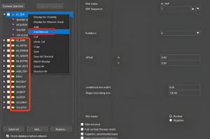
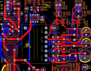
Circuit board design programs convert an electrical concept into schematics, component footprints, routed copper, design checks and production files. The right program is not simply the one with the longest feature list. It must support the board technology, team workflow and manufacturing data your project actually needs. This guide compares seven current PCB tools and explains how to select one without losing sight of fabrication and assembly requirements.
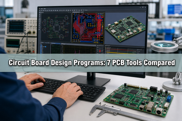
What Are Circuit Board Design Programs?
Circuit board design programs are electronic design automation applications used to create the logical and physical definition of a printed circuit board. A complete PCB environment normally includes schematic capture, symbol and footprint libraries, component placement, copper routing, planes, vias, design-rule checking and fabrication outputs. Some suites add circuit simulation, signal-integrity analysis, mechanical co-design, supply-chain data or formal release management.
A drawing program is not automatically a PCB design program. A schematic-only tool may describe electrical connectivity without producing a routed board. A circuit simulator can predict electrical behavior but may not create manufacturing artwork. A Gerber viewer can inspect production files but cannot reliably reconstruct the editable source design. Confirm that a candidate tool covers the entire workflow you intend to own.
Which Features Matter in Circuit Board Design Software?
Start with the hardest requirement in the design, not the software brand. A two-layer controller may need only stable libraries, copper pours and basic DRC. A dense processor board can require differential-pair rules, impedance profiles, via constraints, length tuning, power-integrity review and controlled release data.
- Schematic and library integrity: symbols, pin numbers, footprints, part numbers and assembly variants must remain synchronized.
- Rules and constraints: trace width, spacing, drill size, annular ring, differential pairs, matched lengths and region-specific rules should be configurable.
- Board technology: verify layer, blind/buried via, microvia, rigid-flex, high-speed and high-current support before starting the layout.
- Verification: ERC, DRC, 3D clearance, connectivity and manufacturing-output viewers should expose errors before release.
- Manufacturing data: the program should generate consistent Gerber or intelligent product data, NC Drill, drawings and assembly files.
- Collaboration: version control, comments, library governance and ECAD/MCAD exchange matter when several engineers share the project.
- Lifecycle and licensing: confirm commercial-use rights, project privacy, supported operating systems and the cost of the required feature tier.
How Do Schematic Capture and PCB Layout Work Together?
The schematic defines connectivity and design intent; the PCB editor turns that intent into physical geometry. A clean workflow assigns verified footprints, transfers networks to the board, defines the outline and stack-up, places components, routes critical signals, adds planes, runs checks and releases manufacturing data. Forward and backward annotation keep reference designators, net names and component changes aligned.
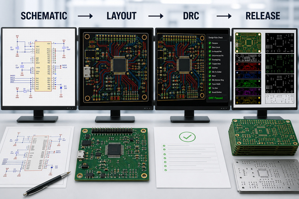
Footprint quality is a frequent source of physical errors. Check pad dimensions, hole sizes, pin-one orientation, courtyard clearance, paste openings and the component manufacturer’s recommended land pattern. A correct schematic symbol connected to an incorrect footprint can pass an electrical check and still produce an unusable assembly.
Which Circuit Board Design Programs Should You Compare?
The seven tools below represent distinct, current workflows. The table is a selection map, not a universal ranking. Product editions and licensing change, so confirm the current package before committing a project.
| Program | Best fit | Key strength | Check before adoption |
|---|---|---|---|
| Altium Designer | Professional teams and complex boards | Unified schematic, layout, 3D, constraints and release management | Required license tier, training and workspace policy |
| KiCad | Open-source commercial, startup and individual projects | Cross-platform schematic/PCB workflow with Gerber and IPC-2581 | Team library governance and collaboration process |
| Autodesk Fusion Electronics | Products with close PCB-enclosure interaction | ECAD and mechanical CAD coordination | Cloud workflow, licensing and advanced constraint needs |
| Cadence OrCAD X | Constraint-driven and high-speed design | Electrical, physical, spacing, manufacturing and high-speed constraints | Configuration effort and analysis modules |
| Siemens PADS Professional | Professional boards, rigid-flex and ECAD/MCAD collaboration | Routing, SI and integrated DFM options | Current PADS-to-Xpedition product path and license scope |
| EasyEDA | Fast online work, makers and distributed teams | Browser access, large libraries and direct Gerber/BOM/Pick-and-Place export | Cloud data policy and complex-rule requirements |
| LibrePCB | Open-source projects needing readable project files | Clean file format, DRC, 3D and command-line automation | Library depth, importer limits and organization-specific features |
Altium Designer
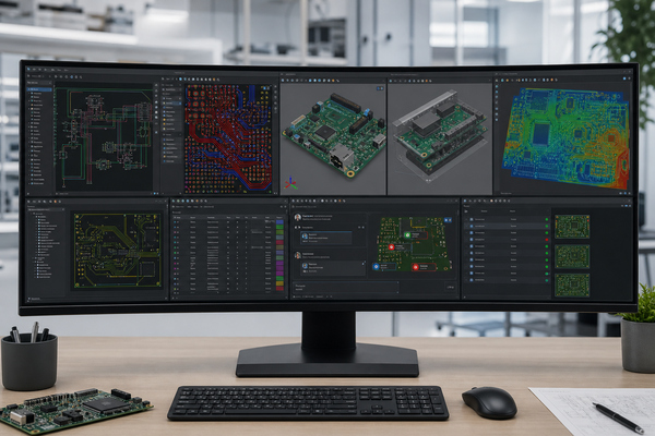
Altium suits projects that need one environment for schematic capture, PCB layout, rigid-flex, advanced routing, 3D checking, BOM management and controlled manufacturing release. Its OutputJob and Project Releaser workflows can package fabrication and assembly data consistently. The main decision is whether the project complexity and team workflow justify the licensing and training investment.
KiCad
KiCad is a free, open-source, cross-platform EDA suite with integrated schematic and PCB editors, 3D viewing, Gerber output and IPC-2581 support. It can handle serious commercial designs when libraries, templates and reviews are managed carefully. Teams should define naming, version-control and library approval rules instead of assuming open-source software removes process requirements.
Autodesk Fusion Electronics
Fusion Electronics is attractive when the PCB, enclosure, connectors and mounting features must evolve together. ECAD/MCAD coordination can reduce outline, height and interference mistakes. Evaluate its electronics constraint depth separately from its mechanical integration, especially for dense high-speed or unusual stack-ups.
Cadence OrCAD X
OrCAD X provides structured electrical, physical, spacing, manufacturing and high-speed constraint management. That makes it useful when many net classes, interfaces or regional rules must remain controlled. The benefit depends on correct setup; a powerful constraint system with incomplete inputs will still release an incomplete design.
Siemens PADS Professional
PADS Professional supports professional PCB flow, mechanical collaboration, rigid-flex, signal-integrity options and design-for-manufacturing analysis. Siemens now directs new users to evaluate the upward-compatible Xpedition Standard path, so organizations should confirm the current product roadmap, data compatibility and module bundle before standardizing a new library.
EasyEDA
EasyEDA combines online schematic capture, PCB layout, DRC, component libraries, 3D viewing and common fabrication and assembly exports. It reduces setup time for straightforward projects and remote collaboration. For controlled commercial designs, verify workspace privacy, revision ownership, footprint approval and the limits of the selected edition.
LibrePCB
LibrePCB is a free, cross-platform suite with schematic-to-board synchronization, multilayer layout, DRC, 3D viewing and human-readable project files. Its CLI can support automated checks and exports in a version-controlled workflow. Confirm that its libraries, importers and output jobs cover the organization’s existing designs before migrating active products.
Which Free Circuit Board Design Software Is Best?
KiCad is the strongest general-purpose free choice when the project needs a complete offline EDA workflow and control over local source files. EasyEDA is often faster for browser-based learning and straightforward boards with online libraries. LibrePCB is useful when clean project files and command-line automation are priorities. For additional beginner-oriented options, see the existing guide to free PCB design software for beginners.
“Free” should be checked at three levels: software license, commercial-use rights and project visibility. A tool may cost nothing while requiring public projects, limiting board complexity or reserving advanced routing and collaboration for another tier. Review the current terms before placing proprietary designs or customer libraries in a cloud workspace.
What PCB Design Software Should You Use for Complex Boards?
Complex boards need constraint depth more than a long component list. For high-speed digital interfaces, look for stack-up-aware impedance rules, differential-pair control, length and delay tuning, return-path visibility and SI/PI integration. The high-speed digital PCB design guide explains how those rules connect to materials and fabrication tolerances.
For an HDI PCB, the software must define microvias, sequential buildup, via-in-pad, stacked or staggered structures and fabrication-specific annular-ring and capture-pad rules. A conventional via rule set is not enough.
A rigid-flex PCB also needs bend regions, layer transitions, coverlay, stiffeners, flex-specific clearances and a stack-up that distinguishes rigid and flexible zones. Choose a program and edition that model these structures explicitly rather than approximating them with drawing layers.
Should You Choose Online or Desktop PCB Software?
Online tools reduce installation effort and can simplify real-time collaboration. Desktop tools provide local processing, offline access and more direct control over project storage. Hybrid platforms combine desktop editors with cloud review, libraries and release management.
| Decision factor | Online or cloud-first | Desktop or local-first |
|---|---|---|
| Access | Fast from supported browsers and devices | Restricted to installed systems unless remote access is arranged |
| Collaboration | Comments, sharing and live updates may be built in | Usually depends on version control, file management or a separate platform |
| Performance | Depends on browser, connection and service capacity | Uses local workstation resources |
| Data control | Requires review of hosting, privacy, access and export policies | Supports local storage but still needs backups and access control |
| Updates | Service updates are generally automatic | Organizations can qualify and deploy versions deliberately |
Choose according to the project’s IP policy, collaboration model and validation process. Cloud is not automatically insecure, and local files are not automatically protected. Account permissions, backups, version history, approved libraries and release control matter in both models.
Which Manufacturing Files Must PCB Design Software Export?
A fabrication package must describe copper, solder mask, silkscreen, holes, board outline, stack-up and special requirements without contradictions. Gerber X2 or RS-274X plus NC Drill remains common, while IPC-2581 and ODB++ can carry more structured product data when both sides support the format.
- Bare-board fabrication: Gerber or intelligent product data, plated/non-plated drill files, route data, fabrication drawing, stack-up and controlled-impedance information.
- Assembly: BOM, centroid or Pick-and-Place file, assembly drawing, polarity/orientation details and approved component alternatives.
- Mechanical verification: board outline, cutouts, height limits and STEP or another agreed 3D exchange format.
- Validation: DRC/ERC reports, netlist or IPC-D-356 when appropriate, and a readme that identifies units, revisions and file purpose.
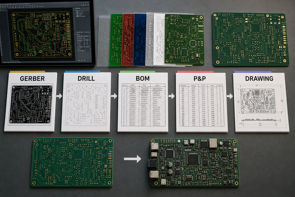
If the board will receive components, the manufacturing release should also match the needs of PCB assembly. Reference designators in the BOM, centroid file, assembly drawing and silkscreen must agree. Mismatched rotations, duplicate designators or unapproved package substitutions cannot be corrected by the bare-board Gerber set.
How Do DRC and DFM Differ?
DRC checks the layout against rules stored in the design program. It can detect spacing, width, drill, annular-ring, connectivity and other geometric violations. DFM checks the released design against an actual manufacturing process, material set, panel method and assembly capability. A design can pass DRC and still require changes because its rules were generic, outdated or incomplete.

Configure the design program with values agreed for the intended construction. Do not use the software’s default minimum merely because it is available. A broader explanation of the factory-side checks is available in the guide to PCB manufacturing software and DFM.
How Can You Validate a PCB Design Before Fabrication?
- Run ERC and resolve unintended open pins, conflicting drivers and power-network errors.
- Verify every new or modified symbol and footprint against the current component datasheet.
- Run DRC with the actual stack-up, copper weight, drill and spacing limits.
- Inspect unrouted nets, copper islands, acute features, mask slivers and copper-to-edge clearance.
- Review the 3D model for connector location, polarity, height and enclosure interference.
- Generate the release package from a controlled revision, then inspect Gerber and drill data in an independent viewer.
- Cross-check the BOM, Pick-and-Place file and assembly drawing for reference-designator and rotation consistency.
Independent viewing matters because it checks the exported result rather than the editable source. Confirm units, zero suppression, drill mapping, layer names and the final outline. Releasing a correct project with an incorrect output configuration still creates incorrect manufacturing data.
Which PCB Software Fits Each Project Type?
| Project type | Software priority | Practical starting point |
|---|---|---|
| Simple two-layer controller | Stable libraries, basic DRC, Gerber and drill export | KiCad, EasyEDA or LibrePCB |
| General multilayer FR4 | Stack-up, planes, impedance rules and controlled release | KiCad or a professional commercial suite |
| High-speed or dense HDI | Constraint management, tuning, SI/PI and microvia rules | Altium, OrCAD X or Siemens flow |
| PCB inside a tight enclosure | ECAD/MCAD exchange, 3D clearance and height control | Fusion Electronics or another tool with verified MCAD workflow |
| Rigid-flex product | Region-specific stack-up, bend and coverlay support | A professional edition with native rigid-flex features |
| Open-source automated workflow | Readable files, version control and CLI checks | KiCad or LibrePCB, after output validation |
For a standard FR4 PCB, even a modest tool can produce a valid design if the libraries, stack-up and fabrication rules are correct. The selection changes when the board requires microvias, flex transitions, high-layer-count routing or specialized analysis.
What Should You Check Before Switching PCB Programs?
Test migration with a controlled copy of a representative project. Import the schematic, board, libraries and rules, then compare the result object by object. Neutral manufacturing formats preserve fabrication intent but are not a reliable substitute for editable source data.
- Confirm that symbols, pin numbers, footprints and reference designators remain linked.
- Check stack-up, net classes, differential-pair definitions, length rules and impedance constraints.
- Inspect polygons, keepouts, rooms, variants, mechanical layers and custom pad shapes.
- Regenerate DRC and manufacturing outputs instead of reusing files from the old tool.
- Keep the original project and a documented conversion report until the new release is validated.
How Does EBest Circuit Support the Design-to-Manufacturing Handoff?
EBest Circuit (Best Technology) supports PCB design and layout, DFM review, prototyping, PCB fabrication, component sourcing and PCB assembly. For FR4 projects, published capabilities include boards up to 32 layers. HDI capability is advertised down to 2/2 mil line and space and 0.10 mm holes, subject to stack-up, board dimensions, materials and engineering review.
The useful handoff is a consistent design release, not a preferred native software brand. Supply the agreed fabrication and assembly outputs with revision control, while retaining editable source files for future changes. Engineering review can then compare the released geometry with the intended materials, copper, drill structure, impedance and assembly process.
FAQ About Circuit Board Design Programs
Is free circuit board design software suitable for commercial work?
Yes, a free tool can support commercial hardware if its license permits commercial use and it provides the rules, libraries and output formats the project requires. Verify current license terms, project privacy and edition limits before use.
Is Altium Designer free?
Altium Designer is a commercial product. Trial, education and related community offerings may have different terms, so check Altium’s current licensing page rather than assuming one entitlement covers commercial production.
Can PCB design software simulate a circuit?
Some EDA suites include SPICE or connect to dedicated simulation tools, but simulation coverage varies. Circuit simulation does not replace PCB layout checks, signal/power-integrity analysis, thermal review or prototype testing.
Can you move a PCB project between design programs?
Importers can move part of a project, but rules, libraries, polygons, variants and specialized objects may not translate completely. Validate the converted source and regenerate all manufacturing outputs before using it for a new revision.
What files does a PCB manufacturer need from design software?
For bare-board fabrication, provide the agreed Gerber or intelligent product-data package, NC Drill, outline, stack-up and fabrication notes. Assembly additionally needs a BOM, Pick-and-Place file and assembly drawing with consistent reference designators and orientation.
Do circuit board design programs replace engineering review?
No. The software checks the rules and models configured in the project. It cannot infer every material, fabrication, assembly, thermal, test or reliability constraint that was never entered.
Conclusion
Select circuit board design programs by matching their verified capabilities to the board technology, collaboration model and release data required. KiCad, EasyEDA and LibrePCB cover many accessible workflows, while Altium, OrCAD and Siemens tools add deeper control for complex projects; Fusion is especially relevant when mechanical integration drives the design. Whichever tool you use, validate libraries, rules and exported manufacturing files before release. For support moving a completed design into PCB fabrication and assembly, contact sales@bestpcbs.com.